Showing posts with label rear. Show all posts

Tuesday, January 30, 2024

NewOld Floored

It has been an unusual start of the year and as such I have not been posting much. Today's post is a quick update of the swirling chaos with NewOldHouse.

On the Level
finished floors
As we started to approach a return to getting the kitchen done, Boo and I realized that if the floors are not level then any cabinet install will be crooked. Then, when we get around to getting the house leveled, the cabinets would not be anymore. So, we had a foundation company come out. They added 2 beams and a bunch of house jacks to get the main house and the 1960's addition leveled. Prior to their work, I had to completely clean the crawlspace as they would not enter a space that had a suggestion of asbestos or rodent. To remedy, I added a 30-foot (10 meter) hose on old PigPen (shopvac). I set the PigPen outside and crawled around under the house for literally 3 hours vacuuming the entire vapor barrier and collecting other debris into a thick plastic garbage bag. The foundation guys were here for 2 days, and now the house is level. A couple of doors which didn't ever close right now close properly and when I sit on an office chair in one of the back bedrooms I no longer unintentionally drift across the floor.

Add Laundry
The prior owners had their laundry machines in the garage. When we moved in, we brought a set of stacked machines and set them next to the large concrete sink just outside the kitchen where the prior owners had theirs. This worked fine, but with where the sink was located relative to the garage door, placing machines near the sink effectively prevented the garage from storing a car. So, we removed the sink and built a small platform (in-process picture below, right) just outside the kitchen-to-garage door. With the machines on the platform, the full width of the garage door is available, so we can one day park a car out there. We hooked the machines back up to the original sink fixtures, routing the waste into a temporary waste-stack. We haven't decided how we are going to finish this space. We will probably frame in walls around the area where the machines are, complete with a ceiling, so they are at least visibly separated from the garage. Around while this was getting built, the garage door was fixed so it opens and closes again.

Kitchen Plumbing
laundry platform framed
We knew the kitchen install was coming, so we went searching for a plumber. The plumbing trade, like so many, are significantly stressed by the current labor environment. I suppose, a couple generations of convincing every high-school student that they need to go to college and not explore trades has not helped, but finding a plumber or electrician who can start the work reasonably soon is virtually impossible. It is reasonable to expect at least 2 months delay. When we contracted our plumber, we indicated that we were 100% flexible and they could send someone over as a schedule-filler even if our project had to be left part-done for weeks. Having this kind of flexibility proved to be a real winner: a plumber arrived the following day, mid-morning, having to leave a job where they weren't ready. 2 days later, our kitchen and attached laundry were rough-plumbed in, and the laundry machines were again operational.

NewOld Floor
Before we moved into this old farmhouse, we had the floors in most of the house redone. The kitchen was still in a semi-demo state, so that area was left alone. Once the demo was completed, and the furnace moved, the floors in the front half of the house could be addressed. Since we now lived here, we needed to further compress our living. So, for about 2 weeks (there was an ice storm in the middle that delayed the flooring work) we used a 10' by 10' space for living, dining and cooking... and the space also held our piano and refrigerator. Needless to say, it was some cramped living, like you couldn't turn around it was so tight. Seriously, you could walk in, but then had to back out.

The flooring guys were pretty magical. They sourced 2-1/4" rolled red-oak flooring matching what was already in place and then feathered it into the existing floor. They repaired in the hole where the furnace used to be, and added a clean crawlspace-access where I had cut the big hole to send the furnace. They spent 2 full days getting the floor installed, filled, stained and clear-coated. The finished floor looks like it was always that way.

Back Door
back door
Before the flooring guys could start, Boo and I needed an escape route. Their work was going to cover the front half of the house and our only egresses would be blocked. We had intended to add a back door eventually, but needing a means of getting in and out of the house moved it to the front of the list. For a hot minute we thought about climbing in and out of a bedroom window. Once the ice storm hit, we were grateful we did not go that route. We added a basic large-windowed (double paned) door that allows a considerable amount of light into a part of the house that had been rather dark. Outside the door, we added 3 steps down to an odd sidewalk that runs along the back of the house. Eventually, we will add a permeable patio back there, but for now, it's where Zed and Oliver are parked (on top of tarps and patio blocks, covered with fairly high-end car covers). The picture on the right, here, shows the after affect; there used to be a built-in bookcase where that door now sits.

All of this activity has been consuming most of our energy. Around these larger items, we had insulation blown into the attic space and I have had to make a few adjustments to the heat distribution as the power of the fan has blown off a connection or 2. I also moved the thermostat so it passes up inside a wall and is attached in it's permanent location opposite the front door. 

Next, the kitchen install work starts with some wall insulation, drywall, and electrical followed by cabinet installs and some appliances. At this rate, we could be making meals in the new space by Easter. 

Thanks, as always, for following along-

Wednesday, November 22, 2023

Hapy Update

Today I could continue the dissertation on the effort to move the furnace in our 1948 farmhouse. Instead, I actually have something car related... the check-in on Hapy that I said I was going to do in a prior post and then flat-forgot. Remember Hapy? He's the 1972 VW camperbus that launched this blog. I meant to post this yesterday, time got away from me.

Hapy No Start Returns
A few weeks ago, as the weather turned cold, Hapy became increasingly difficult to start. Again. I figured it was the same issue as last time (See Hapy No Start Again), and started checking things with my multi-meter. I started where the old problem was: the main fuse for the glow plugs. Nope, there's a clean over-12V signal there. Then, I checked the voltage at the relay, and it was fine there too. Same for the resistance in the wire and the fuse.. no issues. So, I started thinking about the glow plugs themselves. I swapped this set in when I put in the chipped CPU and bigger nozzles, but not because there was anything wrong with the ones that were in there. I had this set of plugs that I had lying around for a few years, and I was selling Flash. Flash had failing glow plugs (resistance tests between the plugs were not within a few ohms of each other). So, rather than put the new set into Flash, I got selfish and put Hapy's nothing-wrong-with-them plugs into Flash and installed the new-never-opened plugs into Hapy. Looking back, I don't think these plugs were nearly as good. I think we have had starting-while-cool problems from the beginning, but it was Summer when I did the swap and never thought about it. Until now.

I pulled the rear-most plug (#4?) and tested it by resting the glow plug threads against a grounded bit of steel on the engine and triggering the ignition to "run". After a 3 count, the tip of the plug started to glow orange. After another 3 count, I could hear the relay click off, and the tip returned to black. I did this a few times and each time it took a few seconds for the plug to respond and even then it was only the very tip. Based on some internet imagery, I concluded that those plugs were insufficient and bought a fresh set.

A few days prior to installing the new set, I started hitting the in-engine plugs with some Kroil penetrating oil at dinnertime. I did not want a plug to break off or damage the head during removal. Whether it was necessary or not, the plugs removed relatively easily. All of them had soot on them when they were removed. Into the trash they went. For each of the new ones, I applied some anti-seize onto the threads prior to installing and then only snugged them down (did not torque the snot out of them).

Unfortunately, my efforts to start Hapy when the glow plugs were not working did a number on the starter. Again. So, my attempt to start him after replacing the glow plugs was not fruitful. Since I did the glow plug swap around the furnace work, and the furnace still is not operational, I self-limited my time to just swapping the plugs and then getting back under the house. I returned the following weekend (bumming rides and car-sharing with Boo the week between) to remove and inspect the starter.

should be 1 part, not 2
I admit, I expected the starter to just need a remove / re-install cycle. I was wrong. This rebuilt starter was installed in June 2023. After a summer of being my "daily driver", the starter was cycled well less than 500 times. I guess rebuilt Bosch starters are not all the same. Maybe the starter was a Bosch but the rebuild was done with cheap-o parts, leaving just the case as a Bosch unit. Regardless, it did not take very long to notice that the seal on the end (which is supposed to go around the shaft which juts out when 12V is applied) wasn't there anymore. It had potato-chipped inside the little pocket where the nose of the starter goes. Neat! So, off to the internets I went looking for a suitable replacement. I decided to get a new one from MetalManParts. Run by MetalNerd, his site only sells things that he personally fabricated or installed into his own vehicle. I have purchased both types of things from him before and have no regrets. Since Bosch was sold off to Seg Automotive, he now supplies new starters from them. I trust that if he is selling them, he is using them.

Sadly, the install of a starter has become fairly rote, since I've done it so many times. I simply put a 19mm socket, 13mm socket, a ratchet and a couple extensions into my pocket, slide under the bus with the starter and it's installed in less than 15 minutes now. If the rear sway bar were not there, I could probably have it done half that time. Of course, I ran the battery down with all my glow plug testing, so it got a spell on the battery charger before I could test my handiwork. Once that was resolved, I turned the key to "run", counted to 6 (for the glow plugs, it's 45*F here) and returned the key to "off". I repeated and then tried to start. Fired right up! I let him run a few minutes to top off the battery and now he is back to being my daily driver.

Hapy Heat Not Heat
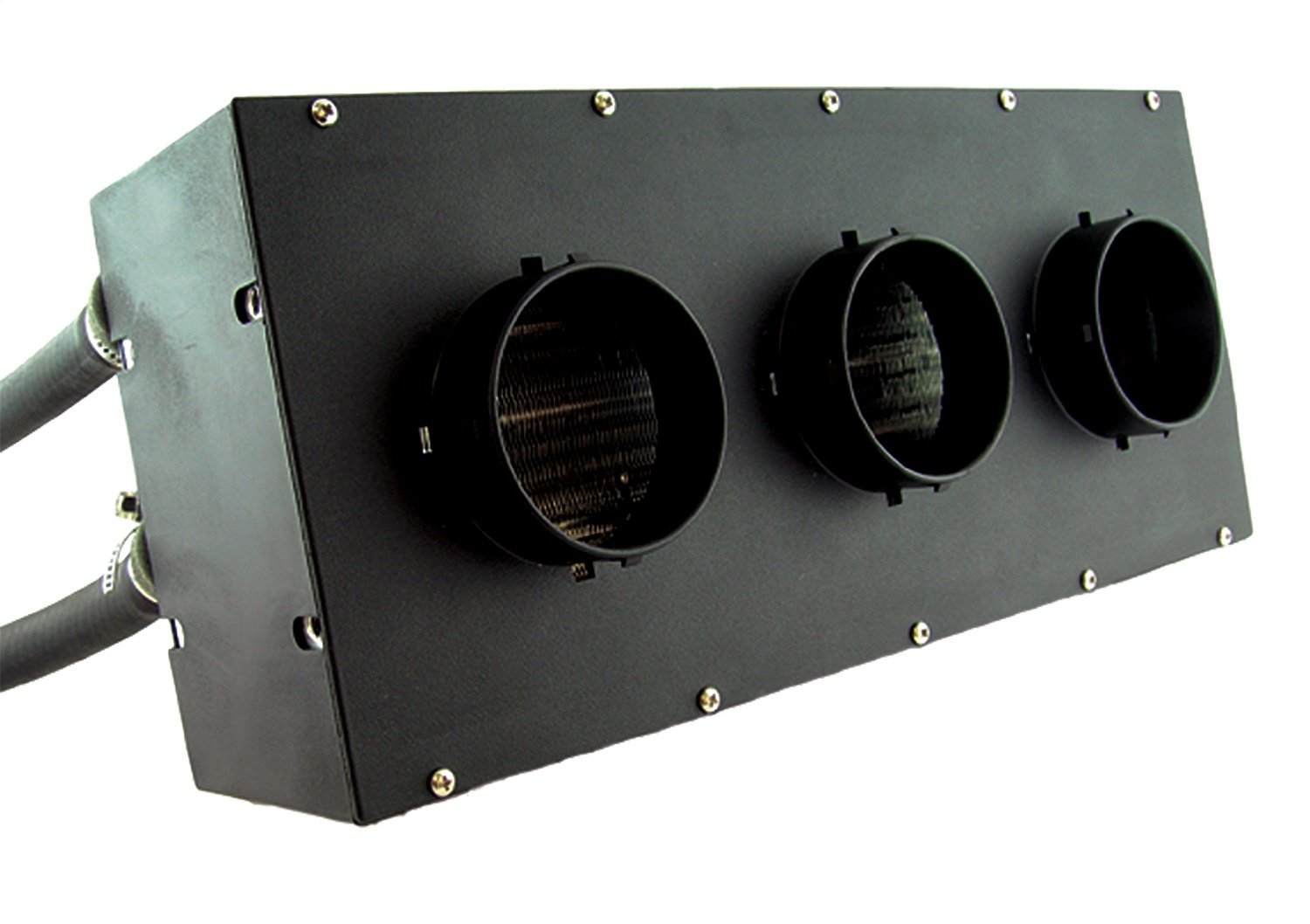
Remember all that effort I went through to install the Vanagon rear heater under the bus for some heat? While that was fun, the result is not much heat. I described the lack of warm on the drive to and from the Cascade Equinox festival. Beyond the lack of detectable warmth, opening the valve to try to get heat has resulted in a coolant leak. I can attribute no other source for why Hapy's coolant level is suddenly not holding. So, I turned the valve back off and will be replacing the Vanagon rear seat heater with something else: a Maradyne Fans Stoker heater.

Maradyne, but could be any
There are lots of auxiliary fans which all look the same and have the same spec's (300cfm, 40k BTU - airflow and heating capacity, respectively). JEGS has their own, for example, that looks identical. Since I am unsure who is the originator, I went with a manufacturer with a known, solid reputation. There is little documentation and hardly any photos of this particular unit on the interwebs, making this choice perhaps a little more risky. I find the 40k BTU number everyone is using to be gross hyperbole, but I don't know how to test that nor the 300cfm number. I will bench test to get some amp-draw numbers before I install it. The amp-draw might be useful information for the next person since even Maradyne doesn't list this detail on their product page. And, it could be one more thing that is exactly the same on all of these units. For future reference, the JEGS unit draws 5.5, 7.1 and 11.6 amps (for low, medium and high settings respectively). I had relays in-place for the medium and high draw switch positions for the Vanagon unit. I don't know if I  will re-use them. Perhaps the amp-draw numbers will help me decide.

One other thing to point out: none of these heaters ship with a coolant control valve. Since I was leveraging the valve in the Vanagon, I have to add one of these or the heat will be on maximum all the time. I included this "vintage" control valve in my order. I thought about going with an electric one, but decided that I would really like to re-use one of the big original heat-sliders on the dash to control the amount of coolant flowing into the heater core. That feels more authentic than another knob attached to the bottom of the dash. Of course, I haven't ever had that control cable, so I will be running this either full-on or full-off until I do.

For now, this means that trips in Hapy will be just like all the other trips I've ever made with him in the not-Summer. They will be cold. It will be like driving around in an ice-fishing shed, unless I can either install that heater soon-ish -OR- get the little Chinese diesel heater/furnace working.... or both. Since I do not have a garage and I barely have a 4-meter square piece of concrete to work on... and I have a house furnace to fix, I do not think Hapy's heat will get addressed terribly soon. At least I have the parts for when I do. Of course, now that he is my daily-driver again, I may decide another week without a furnace might be a fair trade for some heat, any heat, in Hapy.

That's it for today. Thanks, as always, for following along-

Tuesday, July 19, 2022

Zed Body Kit Start

Last Summer, amid the economic restart following the CoViD-19 shutdowns, I ordered and received a fiberglass bodykit for a Datsun 280ZX. It arrived too late to be wrapped into the body work, and I ran out of warm weather anyway. Today, I restart the body work on Zed (1979 Datsun 280ZX), with hopes for having Zed painted before I run out of summer this year. Even though there is considerable Summer left, my time is less available this year than in years past. Boo has injured her arm/shoulder, preventing her from moving it per Dr orders, so I am doing a lot more not-car stuff these days (read: lawn care, housework, etc) which all take precious minutes. 

Back to Start
bumper gap set
While Zed was parked under a canopy / car port all winter, that is not the same as sitting in a climate-controlled garage. Or even an unheated garage. Rain does not fall straight down, and wind blows organic material around. So, when I was ready to focus on Zed, I had a few steps to just get him back to where I had left him last Summer. I had been using his interior as a staging area for parts and boxes while working on the sound/noise contain effort in Hapy (1972 VW camperbus). So, logically, the first thing to do was to vacate the interior and shop-vac it out.

Next, the body panels needed a cleaning. Rather than use a hose, I hand washed him with a bucket and scrubber sponge. Still, I was unable to free some of the green haze that had appeared. He would need a sanding in order for the next layer of paint to adhere anyway, so I left what remained to be addressed by the sanding. I pulled out the body kit that had been stashed inside and cleaned it too.

Front Fenders
d-side bumper
I had spent some time wrangling the front bumper last Summer. I could only get so far because I had not completely solved for the fenders yet. Now that the driver fender was ready, I could move forward. I started by simply mounting the fenders with M6 stainless bolts. When I fastened the bottoms, the fenders ballooned out into their proper shape. I had not realized how flat they had been sitting until then.

Rear Bumper
The rear bumper was the closest to being complete, and after spending so much time on just getting things back to the way I thought they were, I wanted a win. I started fiddling with it and I discovered that I had not really prepared the steel rear bumper hidden within: it had rust spots on it and it was still dirty from when I bought it. More cleaning with a bucket and a scrubber and then sanding, rust treatment and a shot of Rustoleum got it ready enough for use. No, I don't really like the idea of Rustoleum on this project anymore than I think you do, but this will protect the bumper well enough, and once I sand a key into it for the epoxy to grip into, the paint choice really won't matter much anymore. After the paint cured (or 48 hours later...), I re-attached the bumper, making sure the height was completely flat, with the same distance between the tail body panel and the top of the bumper. It is into things like this that so much time is lost. Bolting on a bumper takes, like 10 minutes. Getting it exactly height-right, took more like 30.

p-side bumper
Once the steel bumper was set, I returned the fiberglass bumper to position to get it exactly where I wanted it. After some time spent fiddling with it, I was able to set the bumper such that the gap is the same across the rear, from corner to corner, and the seams along the rear quarter panel were consistent as well. I drilled a hole inside each wheel well near the top of the bumper and set it for good with a pair of M4 bolts. With the height set, I set the spread (tilt in or tilt out of the bottom of the bumper) of the lower edge. I controlled this with a second set of holes lower in the panels. Again, I set 2 M4 bolts through the bumper into the rear wheel well. I may eliminate some of these bolts later, after the epoxy sets.

Side Skirts
setting the spread
With the rear bumper looking good, I shifted forward to the little skirtings that run under the doors. I was not 100% convinced these were necessary when I bought the kit, but now that I have them roughed in, I like them. These kits are one-size-fits-none. While that was not really true with the rear bumper, it was definitely true with these side skirts. The length is quite good, and the fit into the wheel wells was almost perfect. I say almost, because I had to cut a small chunk out of the top of the passenger side skirt for it to fit. The issue with these skirts is with the little lip that runs the length of the door jam. These are designed to sit on the outermost edge of the door threshold, but the design has 2 problems. First, the lip is fairly thick so the door does not easily close on top of it, if the door is set at the right height. Second, and perhaps more important, the lip is not at the correct angle from the outer edge of the skirting. So, if you set it in place on that outermost edge, either it is in the right spot, but completely blocks the door -or- the whole skirting curls under the car too much, not aligning with the fender lines and looking horrible. I resolved by cutting off the lip with a hacksaw. Yes, that is a rather destructive move. I considered all the plastic panels on the ToyoTruck and the panels that run under the doors do not have a lip hanging on the door sill. These will now be a same.

fun with Bondo
With the lip removed, I was better able to control the angles. Similar to how I managed the rear bumper, I first set the height by getting the under-the-door edge just a smidge below the door opening. I set the height temporarily with clamps and then bored holes, used more M4 bolts to hold the tops in place.  I added a bolt on each side, near the leading edge of the door, to hold the section of the skirting which will attach to the front fender in place. I will use this bolt for setting the epoxy, but will remove it, or cut the head off, after the epoxy sets. Next, I set the spread so the rear outer edges aligned with the rear bumper lower leading edges. Because of how the skirts were constructed, this left a small gap at the top rear of the skirt. If I pressed the top against the side of the car, the bottom of the skirt would stick out too far. The picture below shows how it lined up. Because of the curve of the body, it is not immediately visually clear that the bottoms align, but they do. 

Body Fill the Gaps
d-side skirt rear
Around the internet, Bondo is a four-letter word. No one admits to using it, but practically everyone does in some capacity. If I were a master fiberglass guy and had all the time in the world, I might have built-up the trailing edges of the side skirts with fiberglass. That would have been the "right" way to do it. I don't have that skill, nor the materials, and, like I indicated at the top, I really don't have that time. So, I chose Bondo, and went full-on ShadeTree with it.

I have the panels attached exactly where I want them, held on with bolts. I don't want to remove them apply some material grind some down, re-attach, wash-rinse-repeat, in hopes of getting it right. That could take all Summer and still might not look that great. I want to apply filler to the fiberglass but not create a Bondo-bond with the side of the car. To resolve, I grabbed some non-stick spray from my kitchen and shot the steel body panels where I needed to fill a gap. I then cleaned the fiberglass with oil/grease cleanser, leaving the non-stick on the steel and I filled the gaps with Bondo. Is this how a pro would do it? I sincerely doubt it. Did it work? It worked well enough to define the lines. Once teh Bondo set up, I freed the panels, leaving them loosely attached. There was not any Bondo stick to the steel. I sanded things smooth and did another pass to get the seams really clean. Last summer, I tried to resolve the don't-stick by taping plastic to the steel, but no matter how well I set the plastic, there were minute folds which appeared in the dried Bondo. The non-stick spray left a predictably smooth line.

Sanding
body sanding fun
I re-attached the rear bumper and the side skirts after sanding the Bondo smooth. Then, I set into sanding the entire car with 320-grit. As I mentioned above, simply cleaning the body was not enough. Besides, I chose to not sand the primer last year, believing it would better protect the paint over the winter. It needed to be sanded before the next coat, be it more primer or color. I will be priming the fiberglass body panels anyway, so I may shoot primer on the rest. I'll decide that later.

I am about 2/3 done with the sanding of the whole body (fiberglass and steel), working from the rear forward. Once the sanding is complete, I will be setting the height of the front bumper ends, and perfecting the front bumper seams like I did with the rear bumper and side skirts. After all that, the fiberglass will be removed one last time for priming.

That's it for today. Thanks, as always, for following along-

Tuesday, June 7, 2022

Returning to Hapy Sounds - Part 3

I think I've touched pretty much every other part of Hapy's sound system this winter/spring, so I guess it's only right to finish it up with improving the head unit install. Of course, no stereo entry is complete without some fun with wiring, so there's some of that too. I am still pushing hard to have the bus ready for camping season. So, while this may seem to be a departure from the shortest trip to complete, we can't go camping or long-distance driving without sounds. In a way, the ability to easily hear the stereo was what triggered the noise containment project. We just gotta have it.

How Did We Get Here?
planning the cut
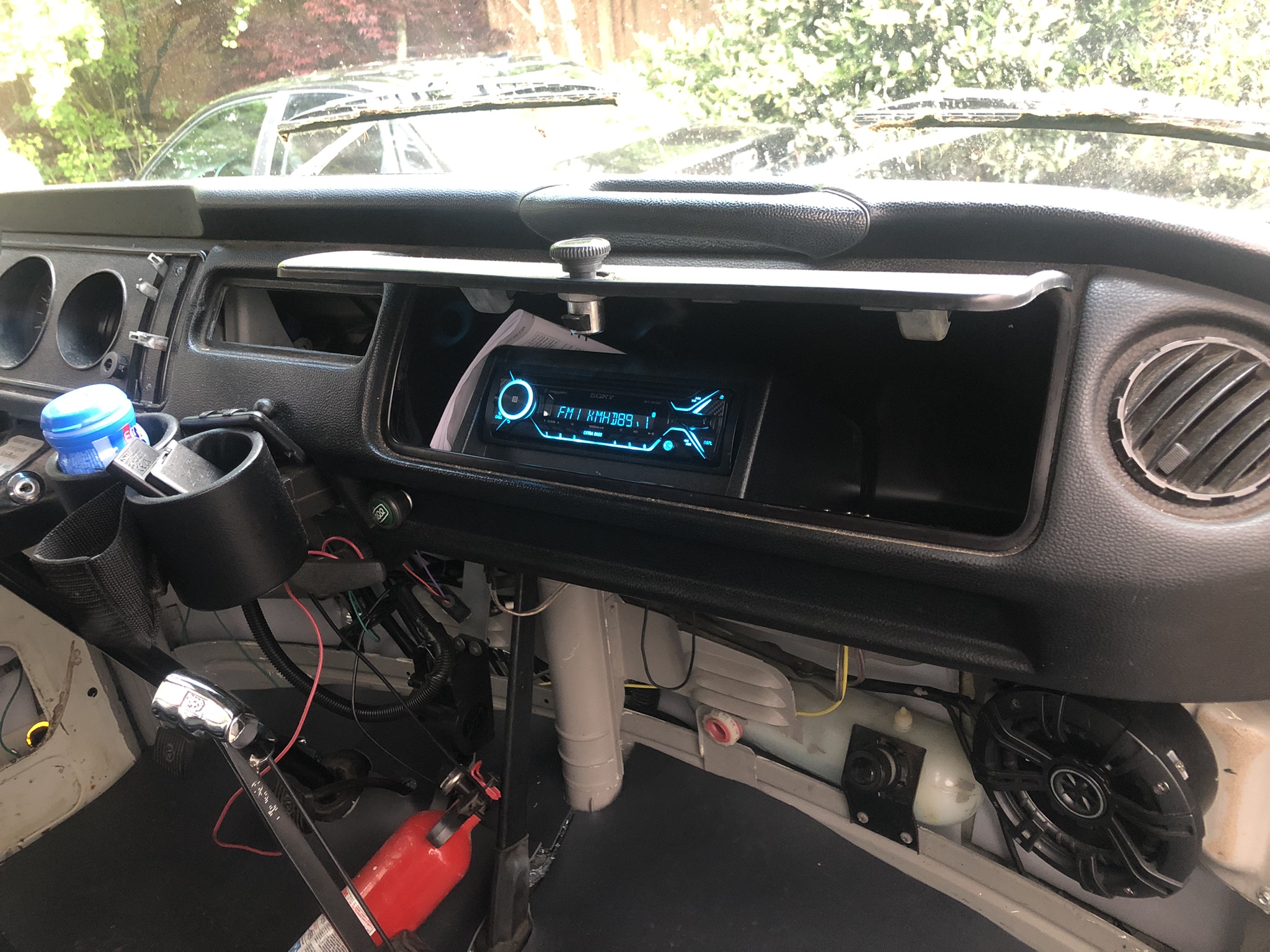
While I was working on getting sound deadener behind the original cardboard glove box, I decided to remove it for better access. I had already disconnected the luxury electrical set up for the electrical rough-in (See Ceiling Wire Rough In), so I simply unplugged the head unit that I had stashed in the glove box and pushed the plug out the hole I had bored in it. After emptying the remaining contents into a small cardboard box, I looked at the glove box. I discovered that the old cardboard box was holding on for dear life, and the removal of the support bar (Phillips screw on the underside of the glove box) did it in. The rear edge (front is front) that is pressed up against the dash had been all raggedy anyway, and once I started removing the box, that edge powdered off in chunks. So, I ordered one of those ABS plastic replacements. With the deteriorating original box in hand, I considered how I could more permanently mount the stereo when the new ABS box arrived. These were on back-order, like so many things these days, so I had to wait a while to complete this.

Solve the Head
mock-up with original box
I got a Metra Universal under-dash mounting kit (model 99-9000), and started fiddling with how that rectangular kit could fit into the rounded glove box. After several measure and test-fit attempts, it was fairly clear that hanging the stereo from the top of the box was not practical. The glove box was too shallow and the mounting kit too deep. I would have had to cut a large rectangle out of the rear of the glove box, and I'm not sure it would have fit right afterwards.

Back when I first got this head unit, I set the head unit in the glove box, on top of the molded shipping cardboard. It fit, and I could manage all of the buttons. Since hanging the box from above didn't work, I tried the kit upside down, mounting to the floor of the glove box. The kit was still too deep, but only by an inch or so. I measured, marked and cut an angle off the rear and it snugged right in. I confirmed that the stereo unit did not extend past the shortest point in the trimmed-down mount-box-thing. To mount the cut-down box to the glove box, things got interesting. I have demonstrated multiple times that I cannot manage to transfer measurements consistently. So, rather than swiss-cheese the underside of the box, I set the kit where I wanted it and marked two holes on the inside (blue tape, then a marker) of the box. I drilled out those 2 holes so I could align the rest of the box from below. I set the box such that the holes aligned and then held it in place with vice-grips while I marked the rest of the holes. Then, I drilled them out. Even then, the holes were not 100% perfect, so I expanded them where needed with a file. I added a hole at the rear of the glove box for the wiring pigtail with a hole saw and then attached the mounting kit with M3 bolts. That sentence took seconds to write, but the work took a couple of hours: tiny bolts + little finger room = patience needed.

Because, Wiring
marking holes
When I did the head unit the first time, I simply ran the power wire on the floor under the carpet. That was very Agile, demonstrated that having a stereo was a good thing, and that leveraging the luxury battery was a great call. So, since the stereo and the rest of the wiring in the bus was torn apart anyway, I changed the wire routing. Similar to the T12 front-to-back cable, I ran 2 sets of speaker cables and a power cable from behind the dash, down through the cable port behind the accelerator pedal and under the bus. I ran this collection of wiring along the frame and then found an existing factory hole (probably a drain hole) just inside of the passenger rear suspension up into the rock-n-roll bed. To keep things straight, the speaker wires were marked with tape (yellow-left, orange-right).

The yellow power wire was routed over to the driver side under the rock-n-roll bed and lightly tucked into place so it doesn't dangle into things and then integrated into the new fuse box (See Luxury Electrical Restored). Onto the speaker wires, I re-integrated the female wire connectors that I had before. One pair of two is under the rock-n-roll bed on the passenger side. Similar to the power wire, I tucked the wires under the rear edge of the bed floor so they stay out of the way. The other pair (recall there were 2 before) was sent through to the other side of the rock-n-roll bed up into rear of the formerly-fridge cabinet. Later, I may switch the female wire connectors to ports, but not today. At this point, I grabbed the floating remote rear speakers and plugged them in.

Back at the front of the bus, I integrated the various rear-speaker wires. Consider there's the pair that run up the A-pillar and to the rear over the sleeping area and the pair that now run under the bus to the rock-n-roll bed. The pair that run under the bus were the same as the pair that used to run along the floor. When I cut them, I marked them left-right. The pair that were sent up the A-pillar, however, were not. to figure out which one was which, I stripped one pair and clipped them together. Then, at the plug at the rear of the bus, I checked the plugs for continuity between the center-hole and the outer ring. One was infinite, the other was almost 0 resistance. 0 resistance is the winner, so I marked the end at the front with the same color tape (orange:right, IIRC) and then marked the other one. I spliced the remote speaker wire pairs together first, and then added the tiny wire from the stereo loom. I expect I will be adding an amp at some point, so I did not soldier them up. 

Putting it Together
note the mounting bolts
With the speaker wires integrated into the loom, the hard part was done. I spliced in ground and the yellow power wire and cleaned up the loom -to- front speaker connection. We were ready for install. The plastic glove box does not fit as easily into the dash as the old cardboard one does. I think it is a little larger, which really is fine. I needed and found a longer mounting screw (about an inch longer) for the support bar. To set the box in place, I found that suspending it in the support strap with the opening pointing up was most effective. Then, the box just tips into place. Since the box is bigger and less malleable, I focused on getting the bottom edge in the right spot, and let the top edge sit high. I sent the mounting screw home and the box doesn't wiggle at all.

I sent the wiring loom, the antenna cable and the wireless phone mic cord through the hole in the back of the glove box and plugged everything in. I took a quick glance at the fuse box and saw the tell-tale red LED telling me that I had a good circuit. Loving that fuse box feature. I set the stereo into the hole added a 10A fuse and fired up the local jazz station. After a few set-up steps on the stereo and burying the excess wire, the stereo is as complete as it needs to be for this Summer. 

So, the stereo is complete.... until I get a wild hair again to change it again. Like, wouldn't it be cool to have remote speaker plugs outside the slider so we can close the door without interrupting the music when set up for festivals or camping? Moments like this are when it is so obvious that this bus will never be done. There are always new ideas.

That's it for today. Thanks, as always, for following along-

Tuesday, December 7, 2021

Handling the Handling (Rear Anti-Roll Bar)

Today, I return from a break with a one-off posting. I remain distracted with non-post-worthy stuff, but I did this work on the bus recently, so I thought I'd post about it. This post covers my reasoning and efforts to install a rear anti-roll bar (called a sway-bar in the US). I could regale you with all kinds of scientific study and test drives leading me to doing this. The reality is, I bought the EMPI kit last Summer ($180US delivered) and it has been sitting in a somewhat large box in my somewhat small garage since. In a way, I installed it because I needed the room. I mean, we just can't keep tripping over, or piling things on, this box, besides I paid $180 for it. That's not a small sum to just not use.

Where Were We
Recall the drive to Leisureland (See Leisureland Road Report) and the drive to/from 4Peaks in the Summer of 2021 (See 4Peaks 2021 Road Report). The wind and passing trucks buffeted the bus, making handling extremely difficult. I had to slow way down on the drive east through the central Oregon desert simply because I could not keep the bus under reliable control. That was scary. I started with the simple: stiffen the adjustable shocks (See Handling the Handling - Shock Adjustment). This helped, but on our next drive out the US-26 for Hapy's birthday, the passing trucks and crosswind still impacted the handling. Consider this quote from that test drive: "he held the road. I needed both hands on the wheel, but it was not (a) white-knuckle experience." <- that is not exactly the description of a solid, love-this-handling suspension that you would want to take for long trips.

I want to see if I could make it better... besides, I have the kit, I need the room on my garage floor and after two months I really need to get my hands on a car with some tools.

Rear Anti-Roll / Sway Bar
CIP1 image has the
bar upside down
Back when I first considered the handling issue, thought through the causes, and was performing my research, I found some other bus owners with similar wind-sheer challenges. These folks were posting on threads talking about the pro/con of a rear anti-roll (sway) bar. RAtwell conducted experiments a few years ago, and most feedback on the interweb is consistent with his findings: the rear bar is great on highways, in windy conditions, going mostly straight, especially when you are burdened with some weight (like camping equipment). Sounds spot-on for my issue, right? Well, there are no upsides without downsides.

For these bars, the downsides include a tendency for over steer (vehicle turns more than turn of steering wheel would imply) while cornering, especially in city driving, and the rear suspension is not as independent so you will feel more bumps. So.. the bar is great on long trips, but around town, where there are speed bumps, sharp turns and potholes, they may make things worse. One point that I found especially interesting is where the long road trip meets city driving: freeway off-ramps. Since you are often pairing rapid deceleration with an increasingly sharp turn, the influence of the rear bar could come into play. This feedback, however, is the opposite of what both CIP1 and EMPI says about these bars. Taken from the CIP1 site: "...These sway bars provide the handling demanded by the enthusiast driver. They help to control body sway and help road adhesion under hard cornering...".

clean rear bar example
So, what about installing a bar and just disconnecting it when you're not doing the loaded-on-the-highway thing? I thought about that. The Jeep and off-road crowd will disconnect one or both anti-roll bars when they go crawling. The fancy new ones allow you to do it from the driver seat with a button. Old-skool involves rolling under your rig and disconnecting the ends, and zip-tying it out of the way. On an old bus, there obviously is not a push-button install option. The bar, however, is not a simple straight bar either. As you can see from the picture on the right, here, that I nabbed from "Goodhand77" who posted it on theSamba, it runs from the mount points at the wheels forward (front is front) and inward to the frame rails. It then dips in the center to create space around the transaxle. So, if you were to disconnect the ends and try to rotate the bar up, the lower center section would rotate up towards the transaxle. More importantly, it approaches the suspension arms. If you just disconnect the ends and let it hang there, it may interfere with the wheel movement. So that doesn't seem like a safe option. In the end, I concluded that the rear sway bar is an either/or: either it is installed or it is sitting in your garage. I got one last Summer and have tried the sitting in your garage option. The handling was unaffected, but the room in my garage was and is, with no value back. So, we're installing it.

Rear Shock Mount Tie-In
instructions
This is the fun part, when we get to put hands on bus. The install is not mentally difficult, but does require boring 4 holes into your beloved, and it can be time-consuming. I have attached an image of the install instructions. The directions start with putting your bus up on ramps (not stands) so you have more room while the suspension is under standard load. They suggest suspending the bar temporarily while you install it, but I didn't. I just let it rest on the ground while I did the rear connections. We remove the lower bolts on the rear shocks, add an "L" bracket, and thread the nut back through. I thought about reversing the bolt so it pointed inwards, but decided that the VW engineers probably had it like this for a reason. Still, when I want to adjust the shocks, it will be a hassle. Into the "L" bracket goes a bolt with a series of bushings and washers, with the bar and the nut completing what looks like a hardware version of a Dagwood sandwich. The bolt through the middle is barely long enough to make the reach, so I had to compress the sandwich while getting the nut to catch a thread. One side was, of course, harder than the other. Slightly longer bolts (provided are 5-1/4") would have saved me an hour of wrestling with the Dagwood, with washer and nut sent flying with each failed attempt. Once the threading caught, I snugged the sandwich together with a few turns on the ratchet: just enough to set the stack and the locknut plastic, without compressing the bushings at all.
 
Frame Mount
p-side frame mount
With the bar connected at the ends, the frame mounts can be test-fit, marked, drilled and mounted. While test-fitting, verify the marked holes with the size of the u-bolt; since these holes are for the u-bolt to go through, this is super-important. I hit the center-points of the marked holes with a hammer and drift so the drill-bit wouldn't wander. My drill bits are getting worn, so the cutting of the holes took many cycles of progressively larger bits to reach the 3/8" target. Once bored out to 3/8", I set the bar up in place and could tell that the inner lip of the frame was going to prevent the bar from mounting flush, so I removed a curved section of the lip with my angle grinder to allow the bar (with the mounting plate in place) to rest against the flat part of the frame. The instructions mention filing, but it would take all day with a file. I shot the area with a quick pass of spray paint to prevent rust. Finally, we're ready to thread the u-bolt through. This is just an exercise in patience, unless one set of holes was not distanced correctly. Fortunately, my triple-checking during the measure-mark step avoided an issue here. The instructions say to put one nut on and to thread the u-bolt through. The nut is to prevent you from losing the u-bolt into the frame. Because of the tight tolerance, the nut needs to be near the tip of the u-bolt, but then it could fall off... leading to the u-bolt disappearing into the frame. Yep, this happened to me on the driver side, but I was able to coax it out with a thin-bladed screwdriver... and more patience.

Tighten Up
rear anti-roll bar installed
Once the u-bolts are dangled down from the frame, use one nut on the u-bolt as you work part of the mount on the other, starting with the base plate. Carefully, push the bar up and then wiggle the u-bolt through the clamp. Once both bolts are through , the nuts are threaded on, tighten the nuts down, shifting from one nut to the other until it is not going to work itself loose while you're doing the other side. Repeat on the other side, and then torque both mounts down. Last, return to the lower shock mounts and tighten everything down. I had left the lower mounts and the sway bar mounts loosely threaded so I had maximum maneuverability while the front was assembled.

Start to end, this took me a few of hours, but only because I move slowly, it was 5*C (just over 40*F) when I did it and my dulling drill bits were a challenge. I probably could have moved faster if I really wanted to as well, but even in the cold, it was really nice to love on Hapy for a little while. Since Hapy is off the road for the winter, and his front seats are out (See Hapy Seating), I was unable to execute a test drive. Still, I expect the handling to be much stiffer, and my garage has gained about 3 cubic feet of floor-space. Win-win. Soon, we will hit the highway for a suspension test.
 
That's it for today. I intend to complete the seat install next, but finding time when the puppy isn't underfoot is the barrier. He needs constant oversight or he will eat something he's not supposed to. He's like a goat that way. He has no interest in being, and it has been too cold (4*C) to have him, tied up outside with me while I work for more than 20 minutes. And, he's too wiggly to just hang out inside the bus while I work on him. So, until I can solve for him, thanks for following along. I will disappear for a while again. If I get the chance to do something, I'll post on it-

Tuesday, September 28, 2021

Zed's Slow Crawl into Fall

It's time for another update on the slow-moving restoration effort on the 1979 Datsun 280ZX lovingly called "Zed". Completely unrelated to Zed, Nemo, the 1997 Audi A4 was sold to a family friend. While he is no longer a permanent resident of our driveway, I expect there will be some ShadeTree adventures as he is improved upon.

Where Were We
p-side front fender gap
We entered the Summer with the goal of having Zed painted before the weather changed from warm-dry to cold-wet. Some years, that change happens as late as Halloween. Other years, like 2019, we lose the end of August to things like wildfires or an early rainstorm. With such a wide range for when the end date might hit, I worked a bunch in the early Summer to set myself up for paint. This year, we have had multiple "false-fall" weather periods, and this week looks like solid rain, leading me to believe that the goal will not be reached.

Recall, we hit a snag with CoViD-19 related manufacturing delays on the body kit. I ordered the kit in May, and it delivered in August. During the delay, I perfected the body as best I could, got the final primer shot and clowned on other cars while I waited. Once the kit arrived, I let it sit in the sun on my deck for a couple of weeks to complete the off-gassing while I took a few camping trips. Of course, sitting outside like that allowed the various pieces to get dirty and have nature fall on then, so they are not as pristine-looking as they were on delivery day. Regardless, they need to be sanded, and primed at minimum before painting, so this just added a cleaning step before the sanding.

Front Bumper
d-side front fender gap
To prepare for the front fiberglass bumper install, I first needed to expose the steel bar wrapped inside the chrome and rubber bumper originally installed on Zed. I had removed the bumper, brackets and all, earlier for access to the radiator supports for primer shooting. The bracket-to-body bolts are 17mm, and there are 4 per side. The bracket-to-bumper nuts are 14mm, and, again, there are 4 per side. I addressed the surface rust on the brackets, shot them with the same finish primer and set them aside.

The original / stock bumper cover is held on with a myriad of bolts and screws. The (10mm?) bolts removed easily. The screws were so rusted on, I had to cut them off with a grinder. Once the steel bar was exposed, I could start test fitting the bumper. I spent a while just fiddling with it: setting it on, tilting it at various angles, etc until I could see how I wanted it. I temporarily mounted the front bumper brackets and the steel bar next, and sat the bumper cover on top. The original location of the bar was 1.5" too far forward.

To recess the front bumper, the gas in the mounts needs to be released, and then the bracket pushed backwards into itself. To release the gas, the steel bar needs to be removed and then a Phillips bolt head is exposed. Remove the bolt, and the gas is released. Then, push the end in. I measured the 1.5" and marked it so I knew when I had it in the right spot. At first, the brackets did not want to compress, even with the gas gone. I encouraged them with a rubber mallet and pushed until the bracket compressed to my mark.

Once compressed, I re-attached the steel bar, and then set the new bumper cover on the bar. This time, it set exactly right, though the ends initially appeared much wider than the fenders want to sit (witness the top two pictures). After about an hour of fiddling with it I found that when the ends of the fender rotated upwards (and the fiberglass shifted left-right a little bit, the steel bar readjusted, etc), they were much closer. Still, actual mounting to the fenders will wait until I have the fenders secured firmly. The fender bolts, like most of the others, have disappeared. The internet thinks these bolts should be M6x1, but I could not even start threading that size. They are also not M5x.8 as those fall right through. I tried generic slotted #12-24 machine bolts next since they are effectively "M5.5", though they also fell straight through. I will return to the M6 bolts and see if I just gunked up the threads with primer. Anyway, with the bumper in place, I can see that I will need to open up the turn signal indicator holes a little bit to allow for the lenses and bulbs to be maintained without removing the bumper. Also, I expect there will be some shaping needed where the hood opens since the bumper is 1.5" deeper.

Rear Bumper
The original rear bumper was the only real rust on this car, which is why we tossed it. I sourced a replacement bar and rear mounts from our friend in Hillsboro. After addressing the surface rust on the brackets similar to the front brackets, I acquired nuts to mount the brackets to the rear (M10x1.25) and attached them. I needed a washer between each of the outer holes on the mounts and the body to angle the mounts inward enough to fit the rear bumper. Onto the brackets, I set the steel bar and test fit the rear bumper. Again, the bracket pushed the bumper out too far to fit. So, I repeated the gas-out process, pushing the rear bumper in an inch. Unlike the front, the rear bumper does not provide an easy means of getting your fingers on the mounting nuts and studs. But, with some perseverance, I got one nut on each side so I could see how it set. As good as the front looked, the rear looked even better. The kit snugged into the body contours, as you can see in the picture below.

Setting the Gaps
p-side rear alignment
When C bought this car, it had been messed up by the prior owner in 2 ways. First, he stripped the interior in the interest of saving a few pounds because he wanted a drift car. Second, he drifted the car into something or someone, damaging the driver door and front fender. We replaced the front door with a donor from WA, but tried to straighten the fender. Off the car after many days of working on it, the fender looked great. Once I re-mounted the doors, hood and rear tailgate, however, the gap between the leading edge of the driver door and the trailing edge of the fender could not be resolved. The edge along the front valence (in front of the windscreen) and above the door also did not line up well. The fold in the driver-side fender had erased the trailing edge and attempts to re-establish it by my amateur hands did not get it there. The image below shows how far off the fender-to-door gap is; the misaligned edge above the door is slightly visible. The passenger side, however, gapped perfectly, with about 1/4" along all of the seams of both the door and the fender so I have a target for the driver side. I spent a couple of hours shifting the door around and improved the gap at the top, but the long edge between the fender and the door could not be resolved. I did not reproduce that edge on the fender quite right.

The efforts to straighten the driver fender has been instructive, but, I will be replacing it. Unfortunately, these panels have not been produced in years, so I needed to find one from a donor car and the one I found is not dent-free. Fortunately, the edges are perfect and it aligns properly with the hood, bumper and driver door. So, once the dents above the wheel well are coerced back into place, the panels will be right. I will then set the driver-side gaps so we have a solid base for the kit. Then, I'll finalize the placement of the bumpers.

Bumper Plan
Both the front and the rear bumper will require a little bit of fit and finish. The rear aligns very well, with only some small smoothing needed to achieve the line I am looking for. The front may require more, even after the fender fit has improved, the gaps are larger. I will see how much this gap closes once I send a couple of screws through. I expect I will need to add material to the inner edges of the bumper along the fenders to make it look right. Once I have the front and rear looking as I would like, I will shift to the two side panels that run under the doors between the wheel wells and then priming the kit.

I do not intend to seal the seams between the fender/quarter panels and the front/rear bumpers. Instead, I intend to have a clean, visible, seam line. This way if there is some kind of damage to the fiberglass from parking curbs or a small accident, the repair will not have to extend past that seal line. This also gives me the opportunity to try mixing flex additive into the fiberglass bumper paint. The "flex additive" increases the paint's willingness to bend without cracking. If I sealed the seam and painted the body as a whole, that flexing additive would need to be part of the paint on the seal or further up fender/quarter panel paint. Otherwise, there could be cracking at the seam, forcing the repair into the steel. This way, the bumper can be removed, repaired/replaced, painted and installed.

What's Next
The ultimate question remains: will the car get through paint before the weather changes? No, but I would rather have it look right than be hurriedly finished. First, I need to get the driver fender replacement undented and prepped. Then, I will get the body kit fitting completed with mounting holes drilled, etc. This would allow me to finish the kit separately (clean, sand, Bondo, sand, clean, possibly high-build primer, sand, clean, finish primer, sand, clean, paint) and then mount it when it's ready. I don't expect a weather miracle that would allow me to get all the way to the end of that task list, though. I expect the weather will turn for good before I'm through primer. Actual paint on the body and the kit will have to wait until next year.

Thanks, as always, for following along-

Tuesday, February 23, 2021

MGB Interior Panels - Part 1

I spent a great deal of time working on Zed's body. Before and after that, I spent even more time on Hapy, with the wiring (both the re-wire and the P0121 code), the furnace and the heater. Around those efforts, I picked up and improved upon T's old Audi, Nemo. Today, I took a break from those other cars to return to Oliver, the 1978 MGB, to complete some interior things I had left undone. I was going to get after Nemo's rear wheel bearings, but honestly, I just want something in the warm garage and Oliver is the only car in a garage, so... off we go into another multi-part post.

Where Were We
Recall that I blew some manna-from-heaven on an interior refresh for Oliver two years ago (See New Seat, What a Treat Parts 1, 2, 3 and headrests). I completely restored his seats, replacing all of the foam and the covers. Out with the old black vinyl and in with new cream with black piping leather. The lighter color is really nice when the sun is super intense, like in the early Summer here. I put in seat-heating elements, but haven't wired them in yet. Instead, I focused on summer-supporting stuff, like the new stereo. This new stereo included front speakers attached to contoured plastic boxes mounted to the outer footwell sidewall (See MGB Gets Sound, Version 2), but the kick panels were not there, so I started with those.

Kick Panels
creating kick-panel pattern
The kick panels compliment the seats in that they are the same cream color. When I ordered these, I appear to have selected the option to include map pockets, which I guess are okay, but with the little speaker boxes, will not be terribly useful. Anyway, in order to pierce the kick panels in the exact right spot so I can mount the speaker boxes, I pulled a paper shopping bag and some cardboard out of the recycling. I traced the kick panel onto the paper and cut out the pattern. I removed the speaker box from the driver-side sidewall, set the paper against in it's place and found the mounting holes with a small nail. I transferred the holes onto cardboard to test the location, and they were a little off. So, I pushed the nails around until they were in the holes well and tried again. They were still a little off, but the third time they were perfect. I transferred the holes onto the rear of the kick panel and drove the nails through from behind with a framing hammer. I set the soft cream material onto a shop towel and set that on top of an old kitchen cabinet door so the nail could pierce without damaging the panel.

speaker box
attached to p-side panel
After presenting the speaker box to the panel, and pressing the mounting screws into their respective holes, I drove the screws into the panel and then held the pair against the side of the car. I needed to position the panel around things, so this actually happened more along the lines of... in, then out, then in then out a few times until the panel was tight against the leading edge of the door weather stripping, the holes were aligned and the screws were lightly threaded in. I verified the routing of the speaker wire and then set the screws all the way in into the speaker box was snug, but not overly compressing the panel. I re-mounted the speaker and turned to the passenger side. I followed was the same process, down to the multiple sheets of cardboard. Since there are fewer obstacles on the passenger side, it was easier, but only barely because I did the whole thing leaning across the transmission tunnel from the driver seat. I could still feel my ribs 2 days later, but they really look good. Pain is temporary; beautiful clean kick panels... well, they're kind of temporary too. Just not quite as temporary, I hope.

Rear Quarters
With the kick panels in, the door panels look that much more black. And wrong. So, I really needed to keep going, but I thought I would do the doors themselves last. There are 2 triangular-ish panels that sit just aft of the seats with the rear-most edge following the contour of the front of the rear tire well. So, I call these quarter panels; I'm sure they have another name, though. I thought they would be easier than the door cards, and with the location of the car so close to the wall on the passenger side, I'm not sure how I will get to the passenger door anyway.

ideal top orientation
to hit all 3 bolt heads
These need to fit under the convertible top mounts, but otherwise their positioning is fairly straightforward. The 3 bolt/screws are partially obstructed by the convertible top frame. So you cannot just lower the convertible top to remove the 3 bolts that hold the mount to the car. You can remove one, but to get to the other 2, the top needs to be partly open. This is where an extra hand is very helpful. I didn't have one, so I tried doing just the driver side first. I started by opening the top so it was sticking almost straight up. This exposed or unobstructed all 3 bolt heads.

When I removed the the rear-most bolt/screw on the driver side, the capture-nut inside the B-pillar fell off (30 year old weld failed). Also, one of the hinge-points on the passenger-side of my convertible top frame separated. The capture nut is easy: they are sold on Moss for around $18US. For the hinge-split, I literally held the pin where it was supposed to go and forced the pieces back together with channel-lock pliers. I looked around for repair kits or something, but I was unable to find anything. At this point, though, it is working.

To get a sense of the work, I did complete both sides (using only 2 screws/bolts on the driver side), one at a time, leaving the other side firmly attached. With the convertible top frame up, just like it is pictured above, remove the 3 bolts/screws. I completely removed one, and then moved back and forth on the other two, slowly removing them. With the frame lightly held in place, I shifted focus onto the panels.
 
The Doing
I tried 2 different approaches, and found the second approach works better. First, I tried to poke a tiny hole in the panel for each of the 3 bolts to pass through and then widened the hole with something so the screw/bolt can thread in without catching vinyl/leather on its way. Take care not to make it so large, however, that it is larger than the frame hole supports. On the passenger side, I used a razor knife to cut a small "X" for each of the 3 holes. Either way, set the panel nearby, and get yourself seated on the parcel shelf at the rear of the passenger area.

I completed the removing of the 2 final bolts while holding the frame steady with my head. Yeah, that's right. This is where having a helper would be very helpful. With the frame held steady (either with your head or by a helper), lift the mount up just enough to get the card in place. I set the rear-most corner in first, and then flexed the card to press the leading edge behind the weatherstripping. The holes for the frame will line right up, but I checked with a bolt to make sure first. Then, I lowered the frame down into place (optional tonneau cover mount held firmly against the top frame), and sent a bolt through, threading into the nut. With one fingered in, I sent the other two in, and then moved from bolt to bolt until they were all snug.

At this point, I have both of the front panels and both of the rear panels in. The doors are a little more complicated since the glass-scrapers need to be replaced, and the old cards are still in. Since the weather around here has been below freezing and wet (ice, freezing rain, sleet and snow), I will be continuing to play with Oliver since he is in the semi-heated garage until the weather changes.This means that my next post will probably include some work on the driver-side door card. The passenger side is trapped against a shelving unit, so I probably will not be getting to it for a while.
 
As always, thanks for following along-
Tuesday, October 20, 2020

Car Ports and Car Noises

What a difference a week makes. In my last post, I mentioned that I had helped T moved some stuff out of the one garage bay. Since then, K got the rest of his stuff, so Oliver is back in the garage. Also, the 2 carports from Harbor Freight arrived. So, I quickly moved from all cars out in the open and no sheltered space to work to 3 cars under some kind of roof, creating all kinds of work space. So, today's brief post if about getting the car ports up, and some diagnosis into the noises coming from Nemo.

Car Port Assembly x2
400 sqft of not raining
I have a small 2-car garage. I underscore small because Oliver (1978 MGB) barely fits between the garage door and the walkway along the opposite wall. Considering the MGB is one of the shortest cars out there, I couldn't imagine parking a Caddy or one of those big pickup trucks. Simply put, it wouldn't fit. So, when I think about how I'm going to complete Zed (1979 280XZ) this winter, I shudder. It's way too small to shoot paint, and with the gas furnace in there, I couldn't paint while heating the house, so the plan unravels fairly quickly. So, I got a couple of those 10' x 20' car ports that Harbor Freight sells (~$120US each). My driveway has a slight tilt towards the garage, but it's otherwise fairly flat.

V between
While I would have preferred a purchase ship-to-store option, the harbor freight website doesn't offer that. Instead, they offer $7US to ship it by FedEx Ground. That sounds like a cost-loss on their part, especially for a pair of these car ports, but they arrived before the primer from Eastwood (which still hasn't arrived). The assembly is actually very easy. The instructions have only a handful of steps and the exploded drawing is not as bizarre as IKEA furniture. I used a rubber mallet to get the pipes to fit together quickly. I was able to get each one assembled in about 2 hours, measured from when I walked out my garage door with a full box to walking back in after set-up and recycling/throwing away the packaging.

I set one over the top of Zed, and the other right next to it. I would rather not have a 20' dripped seam between them, and pushed the posts right next to one another. I took the 8-inch-or-so hangdown from one, and flipped it up over the top of the neighboring car port. The other hangdown, I pulled across and clipped to the tie-down seam, which runs along the inside, above the bottom rail. Then, I forced the pipes together and cable-tied them. This created a small V shape of car port tarp between the rails, running all the way front-to-back. My plan is that this will direct the water down to the lower end of the carport. I think this will work except for those super-heavy rain events we get sometimes. We'll see.

A4 Front Clunk
top of front strut, example
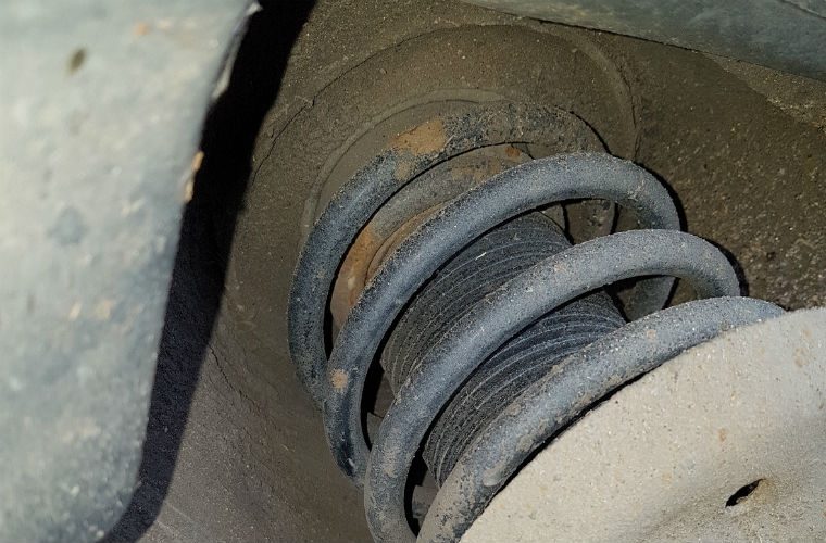
Now for some car content. After getting all the little things fixed on Nemo, I took him for a short test drive to see how he felt. He felt pretty good. Lots of boost, and plenty of power, but he made lots of noise. I could hear a clunk pretty much on every little bump. I figured it was the sway-bar bushings and replaced them: 13mm bolts hold the clamps on, and the bushing has a slit in it so you just need to remove the clamps, pull off the old bushing, slap on the new one and put the clamp back on. Times 2. The noise got a little better, but after pushing the fenders up and down, I believe the problem is in the strut-mount. From what I've read, after market struts that lower the front end (like Nemo has) put more pressure on the strut-mounts than the stock ones do, transferring some of the burden from the springs to the mounts to hold the front end up. This causes them to wear prematurely. So, I will be looking to replace those. Since I have a very healthy fear of strut springs, I will probably remove the struts and have new mounts installed by one of the shops around here. Better to pay with some hard earned cash than with some body damage.

A4 Rear Hum
Also on that test drive, I noticed that the rear end would make a humming noise once I got above about 30mph. I figured it was the wheel bearings, so I put the back end up on jackstands to confirm. The wheels had no play in them. None. Curious, I pulled it out of gear and spun the wheels, listening for noises (that would translate into a hum at speed). I heard clicking coming from the inner CV joints. So, that means at least removing one or both rear axles. Fun. Of course, with the AWD, I can't be 100% sure the bearings aren't bad. I may not have gotten the wheels spinning fast enough to make noise.

the diff oil fill, example
I intended to drain and fill the rear diff while the rear end was up in the air, but the fill plug is stripped. While I was under there, I got to see just how much caked on grease could remain attached to the outside of a differential without falling off. The answer: a LOT. I am really concerned about the health of this diff, and the whole rear-end, for that matter. Before I go any further with it, I will collect a second opinion. After that, I think it will have it's ass-end in the air for a while as I replace CV joints, and/or wheel bearings and fight off the fill plug so I can refresh the fluid. I'm not sure a 20+ year old 230k+ mile A4 is worth terribly much, but this is how we learn, and this could be a useful daily-driver for someone, maybe, eventually.

Well, that's it for today. I have not gotten back into the Zed paintwork since I put up the car ports. I really wanted to get Nemo road-able first. With the car ports up, I have more paint prep to do, and I need to figure out some sides for the car port space so I can heat and paint. Thanks, as always for following along-