Showing posts with label bracket. Show all posts

Tuesday, September 28, 2021

Zed's Slow Crawl into Fall

It's time for another update on the slow-moving restoration effort on the 1979 Datsun 280ZX lovingly called "Zed". Completely unrelated to Zed, Nemo, the 1997 Audi A4 was sold to a family friend. While he is no longer a permanent resident of our driveway, I expect there will be some ShadeTree adventures as he is improved upon.

Where Were We
p-side front fender gap
We entered the Summer with the goal of having Zed painted before the weather changed from warm-dry to cold-wet. Some years, that change happens as late as Halloween. Other years, like 2019, we lose the end of August to things like wildfires or an early rainstorm. With such a wide range for when the end date might hit, I worked a bunch in the early Summer to set myself up for paint. This year, we have had multiple "false-fall" weather periods, and this week looks like solid rain, leading me to believe that the goal will not be reached.

Recall, we hit a snag with CoViD-19 related manufacturing delays on the body kit. I ordered the kit in May, and it delivered in August. During the delay, I perfected the body as best I could, got the final primer shot and clowned on other cars while I waited. Once the kit arrived, I let it sit in the sun on my deck for a couple of weeks to complete the off-gassing while I took a few camping trips. Of course, sitting outside like that allowed the various pieces to get dirty and have nature fall on then, so they are not as pristine-looking as they were on delivery day. Regardless, they need to be sanded, and primed at minimum before painting, so this just added a cleaning step before the sanding.

Front Bumper
d-side front fender gap
To prepare for the front fiberglass bumper install, I first needed to expose the steel bar wrapped inside the chrome and rubber bumper originally installed on Zed. I had removed the bumper, brackets and all, earlier for access to the radiator supports for primer shooting. The bracket-to-body bolts are 17mm, and there are 4 per side. The bracket-to-bumper nuts are 14mm, and, again, there are 4 per side. I addressed the surface rust on the brackets, shot them with the same finish primer and set them aside.

The original / stock bumper cover is held on with a myriad of bolts and screws. The (10mm?) bolts removed easily. The screws were so rusted on, I had to cut them off with a grinder. Once the steel bar was exposed, I could start test fitting the bumper. I spent a while just fiddling with it: setting it on, tilting it at various angles, etc until I could see how I wanted it. I temporarily mounted the front bumper brackets and the steel bar next, and sat the bumper cover on top. The original location of the bar was 1.5" too far forward.

To recess the front bumper, the gas in the mounts needs to be released, and then the bracket pushed backwards into itself. To release the gas, the steel bar needs to be removed and then a Phillips bolt head is exposed. Remove the bolt, and the gas is released. Then, push the end in. I measured the 1.5" and marked it so I knew when I had it in the right spot. At first, the brackets did not want to compress, even with the gas gone. I encouraged them with a rubber mallet and pushed until the bracket compressed to my mark.

Once compressed, I re-attached the steel bar, and then set the new bumper cover on the bar. This time, it set exactly right, though the ends initially appeared much wider than the fenders want to sit (witness the top two pictures). After about an hour of fiddling with it I found that when the ends of the fender rotated upwards (and the fiberglass shifted left-right a little bit, the steel bar readjusted, etc), they were much closer. Still, actual mounting to the fenders will wait until I have the fenders secured firmly. The fender bolts, like most of the others, have disappeared. The internet thinks these bolts should be M6x1, but I could not even start threading that size. They are also not M5x.8 as those fall right through. I tried generic slotted #12-24 machine bolts next since they are effectively "M5.5", though they also fell straight through. I will return to the M6 bolts and see if I just gunked up the threads with primer. Anyway, with the bumper in place, I can see that I will need to open up the turn signal indicator holes a little bit to allow for the lenses and bulbs to be maintained without removing the bumper. Also, I expect there will be some shaping needed where the hood opens since the bumper is 1.5" deeper.

Rear Bumper
The original rear bumper was the only real rust on this car, which is why we tossed it. I sourced a replacement bar and rear mounts from our friend in Hillsboro. After addressing the surface rust on the brackets similar to the front brackets, I acquired nuts to mount the brackets to the rear (M10x1.25) and attached them. I needed a washer between each of the outer holes on the mounts and the body to angle the mounts inward enough to fit the rear bumper. Onto the brackets, I set the steel bar and test fit the rear bumper. Again, the bracket pushed the bumper out too far to fit. So, I repeated the gas-out process, pushing the rear bumper in an inch. Unlike the front, the rear bumper does not provide an easy means of getting your fingers on the mounting nuts and studs. But, with some perseverance, I got one nut on each side so I could see how it set. As good as the front looked, the rear looked even better. The kit snugged into the body contours, as you can see in the picture below.

Setting the Gaps
p-side rear alignment
When C bought this car, it had been messed up by the prior owner in 2 ways. First, he stripped the interior in the interest of saving a few pounds because he wanted a drift car. Second, he drifted the car into something or someone, damaging the driver door and front fender. We replaced the front door with a donor from WA, but tried to straighten the fender. Off the car after many days of working on it, the fender looked great. Once I re-mounted the doors, hood and rear tailgate, however, the gap between the leading edge of the driver door and the trailing edge of the fender could not be resolved. The edge along the front valence (in front of the windscreen) and above the door also did not line up well. The fold in the driver-side fender had erased the trailing edge and attempts to re-establish it by my amateur hands did not get it there. The image below shows how far off the fender-to-door gap is; the misaligned edge above the door is slightly visible. The passenger side, however, gapped perfectly, with about 1/4" along all of the seams of both the door and the fender so I have a target for the driver side. I spent a couple of hours shifting the door around and improved the gap at the top, but the long edge between the fender and the door could not be resolved. I did not reproduce that edge on the fender quite right.

The efforts to straighten the driver fender has been instructive, but, I will be replacing it. Unfortunately, these panels have not been produced in years, so I needed to find one from a donor car and the one I found is not dent-free. Fortunately, the edges are perfect and it aligns properly with the hood, bumper and driver door. So, once the dents above the wheel well are coerced back into place, the panels will be right. I will then set the driver-side gaps so we have a solid base for the kit. Then, I'll finalize the placement of the bumpers.

Bumper Plan
Both the front and the rear bumper will require a little bit of fit and finish. The rear aligns very well, with only some small smoothing needed to achieve the line I am looking for. The front may require more, even after the fender fit has improved, the gaps are larger. I will see how much this gap closes once I send a couple of screws through. I expect I will need to add material to the inner edges of the bumper along the fenders to make it look right. Once I have the front and rear looking as I would like, I will shift to the two side panels that run under the doors between the wheel wells and then priming the kit.

I do not intend to seal the seams between the fender/quarter panels and the front/rear bumpers. Instead, I intend to have a clean, visible, seam line. This way if there is some kind of damage to the fiberglass from parking curbs or a small accident, the repair will not have to extend past that seal line. This also gives me the opportunity to try mixing flex additive into the fiberglass bumper paint. The "flex additive" increases the paint's willingness to bend without cracking. If I sealed the seam and painted the body as a whole, that flexing additive would need to be part of the paint on the seal or further up fender/quarter panel paint. Otherwise, there could be cracking at the seam, forcing the repair into the steel. This way, the bumper can be removed, repaired/replaced, painted and installed.

What's Next
The ultimate question remains: will the car get through paint before the weather changes? No, but I would rather have it look right than be hurriedly finished. First, I need to get the driver fender replacement undented and prepped. Then, I will get the body kit fitting completed with mounting holes drilled, etc. This would allow me to finish the kit separately (clean, sand, Bondo, sand, clean, possibly high-build primer, sand, clean, finish primer, sand, clean, paint) and then mount it when it's ready. I don't expect a weather miracle that would allow me to get all the way to the end of that task list, though. I expect the weather will turn for good before I'm through primer. Actual paint on the body and the kit will have to wait until next year.

Thanks, as always, for following along-

Tuesday, March 30, 2021

Bus Tow Hitch

Today, I covered the install of a tow hitch onto Hapy, (1972 VW Bus), highlighting some of the unique factors about a 1972 VW bus as well as what is special about Hapy that makes this install particular. I am still working on the injectors and getting Hapy running, so this install kept me busy or should I say distracted from that for the weekend.

Slow Go
test fit
Back when I first got Hapy, and for the handful of years I drove him with his original mystery engine, he could barely get much of anywhere if there was more than just me inside. If we added another adult, a couple of kids, gear, food, etc for a weekend of camping every incline presented a new opportunity for my knuckles to whiten, my back to tighten and passersby to wave with a single finger. At the time, I knew of other bus-drivers who had no such problems. In fact, there was a guy from Canada who built a trailer that looked like a small single-axle version of his bus that he towed behind him as he crisscrossed Canada and the US. He called his bus the Red Tomato; sadly, I cannot find a picture, but his set up was amazing. An engine swap, and some other upgrades later, I'm no longer slowing down traffic, and the idea of a small tow-behind or just maybe using one of those tow-hitch bike racks is appealing. Dare I say a ski/board rack?

One Year Only
Of course, 1972 is a transition year for the VW bus. 1971 was the last year of the old "type1" or upright engine, making 1972 the first year of the pancake engine (in the bus). The rear transom was changed so you could no longer remove the bottom section between the tail lights for engine removal, the tail light housings were made larger, etc. On the front, 1972 was the last year of the "low light" turn signals below the headlights. So, 1972 was already a kind of a frankenbus before I got my hands on it. Arguably, if I had left it (or returned it to) stock, it would be worth more.... to some folks. Bear in mind, Hapy did not have his original engine when I got him, so any return-to-stock would not have been to a numbers-matching bus. Besides, a camperbus should be camped in, not just garaged, trailered and car-showed.

dis-assembly
In 1973, the rear bumper was changed, changing the rear end again. This means that much of the design of the engine-to-frame mount, transom, the bumper mount, etc. was unique to 1972. So, getting a rear hitch to fit was not an off-the-shelf thing. Well, it wasn't until this cat in Virginia started making them as a side job a few years ago, and selling them on TheSamba. The reviews of Jeremy's work has been super-high, and his responsiveness to email has been great. It arrived quickly, wrapped with cardboard to protect it (but not boxed, probably for less expensive shipping) and looks exactly like the pictures. You can see what it looked like in the picture on the right, here. What I didn't realize when I ordered it, the tow hitch ships with 6 super-high-strength M10 x 1.5 bolts for mounting. 

These tow hitches include an integrated bumper support, which supplants the old one. So, one of the one-year-only parts is no longer needed. For those who have purchased a bus which had it's rear bumper removed and subsequently lost, with this hitch, you only need to source a bumper (based on my look-around, WestCoastMetric, JBugs, and BusDepot now offer the 1-year-only bumper). That's easier than finding a one-year-only bumper and pair of one-year-only brackets. And, you get a tow hitch. Win-win!

One Bus Only
As unique as the 1972 VW bus rear-end design is, Hapy is more so. Recall, all those years ago when Hal and I (more Hal than I) designed the engine mount for the TDI engine? Rather than leveraging the triangle of mount holes in the frame rail sides that held the original engine mount "moustache bar", we reused the twin holes further to the rear which hold the bumper brackets. This left the triangle mount holes vacant. The tow hitch also mounts to the bus frame through something other than the triangle of holes. Once the install has completed, the engine mount and the bumper mount will each be supported independently.

I will take this opportunity to underscore that our reuse of the bumper bracket holes has been completely without issue. On surface, one could become concerned with whether the holes were designed to support the weight of a TDI engine. Consider that the bellhousing mount to the frame probably holds most of the weight, and is absolutely capable of holding the engine by itself. I say that because I have removed the rear mount and accidentally removed the support (lowered the jack. Doh!) in the past, and the engine has not budged. Also, the bumper mount needs to be capable of holding not just the bumper off the ground, but occasional additional weight of someone stepping on it. Last, it needs some level of hardiness to absorb energy from a rear-end collision. Regardless, I have never felt this design has not been more than capable of supporting the rear-end of the engine. Again, thanks Hal :)

Install Hitch Hampering
bent ear
After some careful examination of the mount, and of the bus frame, I realized that the tow hitch does not reuse the triangle engine mount, it uses a set of otherwise unused holes in the rear of the frame. This means that for a standard 1972 bus, the install does not involve the engine mounting mechanism at all. Nice work, Jeremy! The holes he targeted sit directly above the holes used by the original bumper brackets.... that we are using for our TDI engine mount. In any other 1972 bus, you could just set to tapping those holes with a M10 x 1.5 tap for the supplied bolts. With Hapy, there is always an extra hitch (pardon the pun): the right-angle brackets that are part of the engine mount hung over the outer edge of the frame by about 1/4", and prevented the hitch from setting all the way. Through the use of a cut-off wheel on my angle-grinder, that extra overhang was trimmed off. When I do the install for realsies, I will hit the bracket with the grinder so the edge is smooth. And, of course, I'll shoot the exposed steel with some black paint.

But then, we still were not quite ready. The tow hitch was tweaked partially during shipping. The 2 supports were slightly bent inwards by a 1/2" total so it would not fit around the rails. I pulled out the 3' sledgehammer and encouraged the hitch supports apart. Had the hitch not had a bent ear for the passenger-side bumper support, it could have taken me longer to realize that the shipper was a little rough with the hitch. I advise you to check the measurements and angles when you get yours. These are built on a jig, so it is not a manufacturing issue.

Preparing for the Tow Hitch
Finally, the fun part. With a floor jack, I put upward pressure on the engine support bar so I could remove the bolts on either side. Supporting the bumper with my toolbox, I dropped the last bolts and lowered the bumper. I slid it out of the way and returned the bolts back through the engine support bar. Once the engine mount was tightened back down, I removed the exhaust. I decided that it would be easier to install the hitch with it out of the way. It was at this point that I cut off the extra meat on the brackets and discovered the rough handling during shipping I mentioned above. I decided that the engine was crazy dirty, and I had gotten enough oily yuck in my fingers (I found and re-connected a breach in the compressed air / turbo pipes) that a degrease was overdue.

crazy cleaner
Product shoutout: Oil Eater. I cannot believe how effective this bio-degradeable, enviro-safe degreaser is. I have found this stuff at the dollar store and BiMart, and when I first bought it, I didn't think much about it as I'd never heard of it. Wow, this stuff cleans oily greasy messes fast. My TDI engine was a black-caked oily mess. I shot it with the OilEater, and hosed it off. To get all the little nooks I did this 3 times. No brushing, no scrubbing: just spray it on and hose it off. The engine is incredibly clean now. You can sort of see in the bottom picture. All that silver used to be black, and all that black used to be, well, black, but caked oily gross black.

At some point, the original bumper brackets, and splash pans need to be removed from your bumper. The picture at the top shows the yardsale that ensues when you do. The hitch has the corresponding holes for re-using your splash pans. I recognize that these pans help hold the front edges of the bumper to the side of the bus, but I am not sure that value offsets the cost of the junk that builds up in those pans. Leaves, pine needles, etc sit there and just encourage rust. Washing or cleaning those pans is not easy either. So, for now, I will be omitting my splash pans, and will eventually form a bracket to go from the side of the bus to the front of the bumper. As I worked the bumper, I noticed that the paint needs to be refreshed and the bolts were all rusty again. Fun in the rain-soaked Pacific NorthWest. Finding stainless steel fasteners to replace the zinc-coated or plain steel took some time, but I found them at BelMetric for about $15US delivered.

Installing The Tow Hitch
tapping last M10 hole
With the bumper and exhaust out of the way, and the engine bay clean, the install of the bumper is relatively straight forward. The 6 holes need to be tapped with a M10 x 1.5 tap. I didn't have any, nor had I ever done anything like that, but the tap and driver cost me about $18US at the corner Ace Hardware. The cutting of the threads was pretty easy too. I just took my time, making sure the tap was lined up well, and then slowly twist the tap in 1/4 turn at a time. I found that the first few threads are the most important and that it was easy to mess them up when I was removing the tap. So, my advice is to take extra care during the last few turns on the way out. It is easy to lose concentration, and then you have to do it again.

Jeremy's (the fabricator's) instructions for the install indicate that you must mount the bumper before installing the hitch. I, of course, did not do that, but it was so I could get a test fit. And, as I mentioned above, my bumper bolts have rust appearing on the bolt heads, so I'm going to replace them. The tow hitch is not balanced, wanting to tip down to the rear. I suspect that once the bumper is added, it will want to drop rearward all the more. Considering that at this point I do NOT have my exhaust installed, I expect the final install will end up another post.

note location relative
to engine mount triangle
I set the driver-side end of the bar under it's install location but on top of my toolbox. I went over to the passenger-side, lifted it into position and finger-threaded the upper rear bolt into the hole a few threads. Then, I switched to the driver-side, threading in both rear bolts, but again only a few threads. I continued to bounce back and forth wiggling the hitch and threading bolts until all of the bolts were threaded in. At this point, I pushed and pulled to get the tow hitch into it's rear-most location and then finger tightened the bolts. Last, I ratcheted them down snug (not torqued) with a 15mm socket.

Bumper On
To complete the test-fit, I set the bumper in-place and threaded the 2 outer, but rear-facing, rusty bolts through the hitch-resident bumper support and set the 13mm washers and nuts on. This gave me an approximate visual for how the finished product will look. Overall, I think it looks great. While I will miss the modesty skirt thing, and I have not yet confirmed that the exhaust will fit without modification, I will definitely appreciate having that hitch for a bike rack, or equipment shelf or for actually towing something small.

That's it for now. I will be cleaning up the bumper and exhaust, probably painting the bumper again and then repeating this install, plus re-installing the exhaust. I'm sure I'll post on it. Thanks, as always, for following along--

Tuesday, October 23, 2018

MGB Exhaust Re-Do (Part 2)

Picking up where I left off, we have the MGB front end on jack-stands and the old exhaust sitting in a heap in the driveway. Today's post will be about getting the new exhaust installed. Recall, it is a ceramic-coated stainless steel Bell system. I left the packing plastic bags on the pipes as I handled them to protect the finish, removing the plastic as I installed them.

Setting The Scene
exhaust hammer example
from streettechmag.com
With break time over, we set to trying to install the new exhaust. The Bell system has 5 pieces: the header, a straight-ish pipe, the center resonator, another straight-ish pipe with a support bracket attached and then the tail muffler. They go on in that order. The hardest part, like with any car, is getting the header to fit around all of the various other things in the engine bay. I watch car shows on Velocity and some of those installs require hammering on the pipes to get them to fit. That would really suck. Spend all that money for a "bolt on" set of pipes and then have to dent the snot out of them to fit an otherwise stock engine and compartment. Doesn't seem right, but does explain the custom fabrications they do on some of those Velocity shows. Even then, it's usually because they're slamming a huge non-stock engine into a classic-ish car. For a built-for-stock engine, hammering dents into the pipes shouldn't be necessary. Anyway...

From Below?
For the MGB, this saga starts with getting the front end way up in the air. We had a good 18" of clearance and still couldn't feed the header up from below. Some internet posts I've read indicate this is super easy, but I suspect anyone who installed that way had a lift or a pit. We have neither so we switched to going in from above. That meant removing the bonnet.

From Above
attached for fitting the rest
of the pipes
The bonnet is held to the hinges with 2 bolts per side, but remove the hood prop first. Once the prop is off, one person holds the hood still from the front while another person (K2 in this case) loosens all the bolts, and removes one from each side. At this point, it would be wise to put a shop towel or something soft under each rear corner of the hood. Then, remove a final bolt from one hinge. Balance the hood on your shoulder and let it slide down onto the towel. Repeat with the other side and then each person grabs a side of the hood and walk it off the front. For fun, we set it (on pads) on top of the 280ZX hood. The MGB hood looks like a toy hood compared to the Zed hood. The MGB hood is at least 6 inches smaller all the way around.

center-mount bracket
With the hood removed, you next loosen the driver side engine mount. The two nuts which hold the engine to the mount are the easiest to get to, and present the least necessary to separate the engine from the frame rail. With nuts safely stowed, place a wood block on a floor jack and slide it under the driver-side of the oil pan / engine block. Carefully lift the engine from below (setting the block of wood so the oil pan and other parts are not damaged) an inch or so. Once you feel considerable resistance to the lift, stop lifting. Now, have your helper fit a pry bar between the engine mount and the engine and then apply pressure to shift the engine slightly towards the passenger side. The engine will more roll anti-clockwise than slide left-to-right, but this creates enough space. Hold the header vertically, with the head-tips pointing across the top of the engine. Slide the header as far down into the largest space you can go before rotating the header so the head-tips point up and away from the firewall. On this particular header, there are pinch-welds along the sides of the collector. These pinch welds wanted to hang up on pretty much everything on the way down. With some gentle and some not-to-gentle persuasion, the header pushed past the space between the block, the steering column and the frame allowing us to wiggle it into the right spot near the head. At this point, the pry-bar leverage can be released and the floor jack released, letting engine rest back on the mount. We had to wrestle it a little bit, but it settled. Our header ended up with a couple minor scuffs, but no scratches.

To get everything else to align, K2 bolted the header onto the head. K2 was done for the day at this point, and the rest of the install was not going to be as straightforward, so I cut him loose.

Body Brackets
header from below
While K2 attached the header to the head for fitment / alignment, my focus was on the 2 mounting brackets. The center mount reuses the original body mount holes with a new steel and rubber mount that simply threaded in with new bolts (in the kit). The rear mount also reuses the original body mount holes. If yours are still in great condition, you could reuse them. With the body brackets on, I could start lining up the pipes, and get a feel for what went where.

The fourth pipe (second straight-ish) had a bracket that was a simple flat bar wrapped around the underside of the pipe with a round hole at each end. The center-mount kit provided a bolt, 4 large flat washers, 2 plastic sleeves, a bit of metal flashing with holes and some small nuts and bolts. There were no instructions, but you could tell that the bolt went through the holes in the flat bar. A flat washer went between the flat bar and anything else that touched it. Between the ends of the flat bar, on the bolt, went the plastic sleeves and the nut went on the end. Neat. With some careful bending of the flat bar with my channel-lock pliers, I was able to get the operation together. The bit of metal flashing was to wrap around the plastic sleeves and then bolt to the center-mount bracket I had just attached to the car.
second straight-ish pipe mounted

To get the fourth pipe and centermount to align and fit, all of the pipes between that mount and the header need to be in place. Start with getting the pipes in the rough spot you expect them to be. A straight-ish pipe (one that has a gentle bend or two) has those bends for a reason. Align them with the path of the original pipes. Once set in the right location, fit a pipe clamp between the pipes and then slide them together, wiggling the fit so they stay together and are in the right alignment. With careful use of a rubber mallet, I was then able to drive the various pipes together. Remember to set a pipe clamp at each junction before you start pounding things together or you won't have a way of clamping things together.

Rear Muffler
The final hurdle was figuring out the rear muffler mount. The old mount was a real hack job where a prior owner had taken a u-bolt that roughly fit the original body mount and threaded a nut on each end. So bad, but I really shouldn't judge. The original mount was almost German in it's over engineered solution. To the bracket is attached 2 rubber mounts pointing away from the exhaust pipe. To these rubber mounts, a hexagon bracket (with one leg removed) is attached, with the missing leg on the bottom. The missing leg has a pair of holes, one at each end, for attaching a pair of semi-circular clamps. These clamps hold the pipe in place. Unfortunately, they are sized such that if you put them on without any spacers (not included) they will either pinch the exhaust pipe because you tightened them too much or the lower clamp will fall off because you didn't tighten them enough... because you didn't want to pinch the pipe. To remedy, I found a pair of oversized nuts that would slip on, acting as spacers, so I could tighten everything down without pinching the pipe.

Header to Head
see the gap?
Once I had it all assembled front to back, I moved from back to front, tightening the mounts and pipe clamps. Once snug, I shifted to the very front to consider the mating of the manifolds to the head. The MGB came with a few types of exhaust, with 2 particular versions for the models before emissions standards became so tight (in 77) that the exhaust manifold needed to be redesigned. These 2 types have a different thickness of the material through which you send bolts to attach it to the head. The older one (#12H709) is thicker than the newer one (#12H3911). This is important because the intake and exhaust share studs and corresponding nuts. If the thickness of one manifold is not a match for the other, there is not a uniform amount of torque on the various manifolds, creating leaks. This applies to pretty much any combination of intake and exhaust, unless you stay completely original stock. Since the prior owner had replaced the dual carbs on my MGB with a side-draft Mikoni carb, and hacked together a home-grown exhaust, I was going to have to deal with this regardless.

When the header was attached for fitting the other pipes, I didn't look very closely. It didn't matter. With a closer look, you can see the washers were not sitting flush. Adding insult, only two of the thickness differences for the 4 shared studs were the same. To remedy, I grabbed some fender washers of varying thickness, and cut them in half (across the hole) to use as spacers. To hold the spacer in place during install, I used a very thin smear of the copper gasket maker I used on the header gasket. This plan worked great. In about 30 minutes I had spacers in place, and the header torqued down with washers sitting flush.

gap gone
Testing
All of this, nearly 2 full days of effort, lead up to the test fire. Of course, I had to re-assemble the air cleaner, and the hood is still off, but after verifying everything was back together, it was ready. I had been trickle-charging the battery, too, so I was pretty confident it was going to start right up. Fortunately, it did. It sounds great. It has a nice deep tone without being too loud. The biggest difference, I think, is that all of the growl sound comes from the rear of the car now. It must have had leaks before. With all of the rust, that's not a surprise. I wound the engine up to 3000RPM to get a sense of how it will sound on a power pull and it sounds pretty awesome. With the top down, the garage doors open and the rev counter around 3k, I still hit 90+ dB. So, it is no quieter... in the garage with the doors open. On the road, it is quieter in the seat, but I don't have dB numbers to prove it. Just my ears.

That's it for today. I had started reading about how to do automotive interiors (trimming) in preparation for doing the seats and cards on the MGB. I have parts on-order to complete the trunk and woofer box as well. Once those are complete "major operations" will have completed and I will be shifting focus onto the Zed... and then back to Hapy. Thanks, as always, for following along-

Tuesday, May 15, 2018

Back to the Bus: Rad Swap (Part 2)

Continuing from an earlier posting, today I'll cover the assembly and install of a new Mishimoto all-aluminium radiator into the TDI-powered microbus.

Where Were We?
Old rad, for perspective
In the last post in this series, I removed the old radiator from the bus, destroying the wiring along the way. I removed the framing / bracketing that supported the radiator from the old one and cut off the fans. Now stripped bare, we can compare the new and old radiator. The outlets are the same distance apart. The holes that I used to hold the frame on were in the same spots... but... all the other bits for holding the radiator into a Jetta were flipped over. So, the original fan housing (and air conditioning condenser) would line-up, but it looks like the inlet and outlet are on the wrong side (driver-side versus passenger side). And, the temperature sensor that triggers the fans is now on the same side as the inlet/outlets. So, in a Jetta, this could be solved with different hoses. In the bus, this gets interesting.

Bracketing
Because of the reversal of the inlet/outlet, I realized that the front bar where I had 2 radiator mounts attached needed to get flipped over. I cut off the pop-rivets holding on the mounts, and re-set their location the same way I did it the first time: threading the mounts to the radiator... but wait a minute. The new radiator doesn't use screws. It is threaded for bolts. Neat. I found one bolt in my fastener bins that fit, took it to ACE and got 8 stainless steel hex-bolts that fit: M6 1.0 pitch.

installing fans
Once back from ACE, I threaded on the front mounts, lined up where they should connect to the bar and marked the spots. A quick-run with a 1/8" drill bit and the pop-riveter and the front bar was ready again. I then turned my attention to the fans

Fans
I looked at the pile of plastic and foam bits. I thought I could drill a hole through the original bottom-bit and thread a zip-tie through. Instead, I found fender washers that had a small enough hole to allow the zip-tie, but not large enough for the end to slide through. This would work! So, from the bottom, the zip-tie passed through a washer, a foam bit, the fan housing, the radiator, another foam bit and last a plastic zip-tie anchor. To be extra sure, it would all hold, I ran the zip-tie back through the fins and then through the zip-tie head on the bottom.

Cowling
adding cowling
With fans in place, I attached the mounts. The radiator was starting to get a little heavy. We're feeling almost done, until the flip-over design of the mounting points would stymie the work again. The cowling wasn't fitting anymore. The left and right (driver-side / passenger-side) needed to be reversed because of the angles (front pitched downward to catch some slipstream), but it wasn't quite that simple. After some head-scratching, this ended up being as easy as folding the cowling the opposite direction from what it had been. Then, it bolted right on. I concluded the prep by zip-tying the fan electrical leads to the cowling so they wouldn't be buffeted by the passing winds any longer.

Install
One it was in one piece, I took it back over to the bus and slid it under from the driver side. I hung the threaded carabiners onto the eye-hooks on the frame. Then, I put the front bar on the jack and lifted it into place. Once I was able to get the threaded carabiners onto their respective lengths of chain, I removed the jack and repeated the effort with the rear mounts, again doing the driver side first. I checked the movement, verifying that the radiator unit would swing back and forth, front to back and had some headroom to bounce up.

Wiring Re-wiring
install-ready. topside
Now that the new rad is physically mounted, I switched my focus to the electrical. The new radiator did not deliver with a fan switch, but it did have a threaded hole for one. I had ordered one years ago when I wanted to have the fans come on automatically. I just never got to it. So, I ran the threads on the switch with plumbers tape and threaded it into the hole (with the rubber gasket in place, of course). I still don't have the trust that the temperature-sensitive fan switch will work, so rather than wire that in, I stripped out all of the extraneous wiring and set up the switch on the dash to fire both radiator fans and the little motorcycle fan on the intercooler.

For my sake, I'm posting the circuit numbers from the relay:
30: 12V+ this is fused, but unswitched power so the fans can run with the key off
85: grounded
86: to the fans
87: trigger switch. One day the thermo fan switch will wire in here. For now, it's the dash switch

I cleaned up the wiring so it's nice and tidy with the relay zip-tied to the underside of the bus and out of sight. I may wire the fan switch into relay pin 87 just to see if it works. It might be interesting to wire those pins to a light on the dash so I can see what temperature they fire at... for a first step. If nothing else, I could use that as a temperature warning light.

Plumb and Fill
install-ready. underside
With the electrical solved, and the rain well settled in, I didn't want to give up. I was mostly under the bus anyway, and the bus cover provided additional rain-cover so I wasn't really getting too wet. Fortunately, water hadn't started running under me in growing puddles yet. So, with that motivation, I wriggled the longer hoses onto the 90* bends off the radiator and hose-clamped them really tight. It surprisingly took me no longer to do than it took to type. I went around to the back of the bus, pulled the cover up, opened the tail gate and filled the overflow bottle with G-40. This is a process, requiring filling up to the full line and then venting the air out of the lines with the little spigot I installed just below the thermostat. I continue this process until coolant/water mixture comes out the spigot. It took the gallon of G-40 and wanted more. So, I topped off with distilled water (about 1/2 a gallon).

I dodged to the front of the bus, confirmed the fans ran and then disconnected the battery, closed everything up and dashed inside. One day, I'll have a huge garage. Until then, I work in the rain.

I took Hapy out for a test drive, and I believe the swap is complete. I suspect one or more of the hose clamps will need tightening, but otherwise, I think it's ready. If this fancy super-radiator doesn't do the trick for keeping the temps down, I may need to route more air through it. That would mean either lowering it, routing some ducting from the front or both. Here's hoping the super-rad does the job.

Grilled
I made one last change to the set up after the test drive. I had a section of security fence lying around, so I cut a section, spray-painted with a couple of coats of semi-gloss black and slapped it on the front. This will prevent plastic bags and other garbage (that seems to be appearing on the roads in greater frequency) from getting sucked into the radiator, fouling it's ability to cool the engine. I had meant to do this with the original radiator install. Once I did it, I was surprised at how quickly it went from the cardboard package through the tin-snips and paint to install. In terms of actual effort, it was less than 30 minutes. I really should have done this earlier. The picture to the right shows it mid-install. The nut with washer on each lower corner have since been tightened down and there are zip-ties across the bottom as well as on the top corners holding it in place.

That's it for today. I would like to do something with Hapy's brakes before a real trip. I have rear wheel cylinders and I'd like to replace the lines between the master cylinder and the fill reservoir as well as all brake fluid. Maybe I'll get that done before 4Peaks. I hope so. Anyway, thanks, as always, for following along-

Tuesday, May 8, 2018

Back to the Bus: Rad Swap (Part 1)

It's been a long time coming, but today, I cover the removal of the under-belly mounted radiator in the TDI-powered bay-window bus. In a subsequent post, I'll cover the bracketing retrofit and install fun. First, some background.

Background
disconnected front chains
Last Summer Boo and I had three incidents with the bus getting too hot. We couldn't keep up with GratefulEd on the way home from 4Peaks (See 4Peaks 2017 Road Report). Then, we were stranded on the side of the road climbing the foothills on our way to Frog Lake (see Almost Frog Lake). Last, we barely scratched out a round trip into central Washington for Chinook Fest (See Chinook Fest 2017 Road Report). First, I thought it was because I let the coolant level get too low. Topping up with water didn't help. Then, I thought I had caused irreparable damage from using the wrong coolant, and did a complete flush and fill. It didn't fix the issue. On the drive home from Chinook Fest, I promised Hapy that I would replace his radiator before we took another drive. After emptying the bus of camping gear, I parked him and winterized him. He has sat with a Bus Depot bus-cover ever since.

Radiator - (almost) 9 Years Later
draining the coolant
I had to reach pretty far back into this blog to figure out when I originally installed the radiator. My earliest references to it date back to November of 2009, and I already had it in hand. If I remember correctly, I bought it used off of CL that summer for $40. It could have been the summer of 2008 or even that spring, I suppose. I just know that it was a nice warm dry day, and that definitely doesn't happen in November. Regardless, this used radiator from an early 90's Jetta gave us 6 years of service, but I believe it has served it's last trip. Looking back through the posts, I detailed location thoughts (here), how I constructed the frame/bracket (here and here), the cowling, test fitting and final fitting, the routing of the coolant lines, etc. I did not change the design with the new radiator, in fact, I reused everything except a few fasteners and zip-ties.
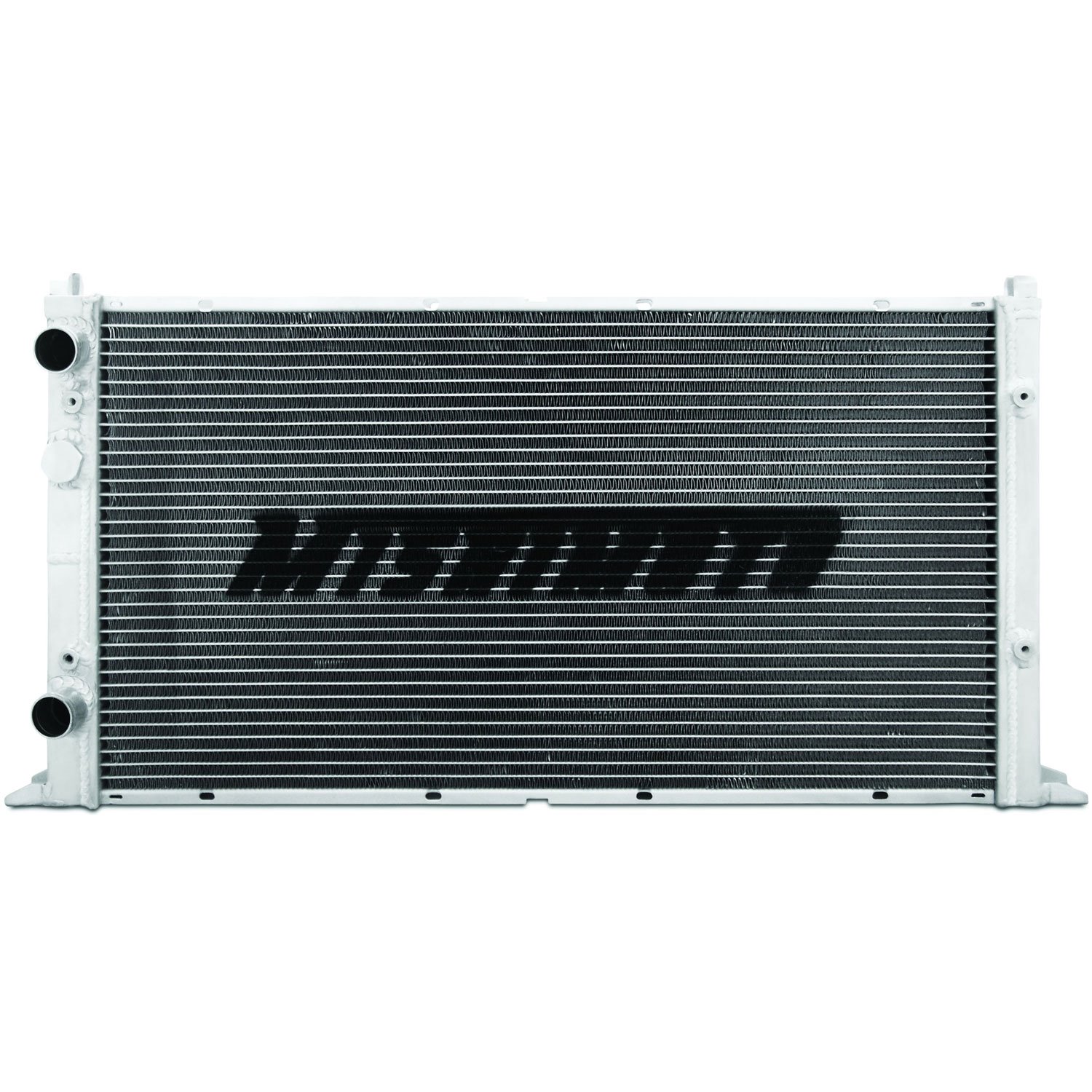
photo nabbed from JEGS,
where I bought mine

Meet the New Rad
I figured that if I was going to buy a replacement radiator, I had 2 options: direct exact replacement (aluminium single-pass core with plastic sides) or an upgraded (multi-pass) all-aluminium one. I considered that I can't say for sure that the original radiator was powerful enough to cool the TDI pushing the bread-loaf down an interstate. When I first did the swap, I babied the bus and I still had my eyes on the temperature gauge. I would really like to stop doing that, so I looked a little deeper into the all-aluminium ones which are supposed to have considerably better cooling capability.

The interweb can't decide if the all-aluminium models are any good. In the mixed reviews, most of the issues appear to be with drop-in fitment, not with performance once installed. Since my fittings are completely custom anyway, I was not deterred. The performance ratings are across-the-board positive, with some actual numbers demonstrating the quality. Of course, not all manufacturers are equal, so I looked to what online vendors sold. There are many radiators which appear to be only sold on eBarf by drop-shipping companies direct from China. That is, except for Mishimoto. The Mishimoto radiators are sold through Summit Racing, ECSTuning, JEGS and a few others. That was enough for me, and I ordered one that was supposed to "fit my vehicle" when I said it was a Jetta3.

It arrived in a very well packed box, designed for shipping and typical shipper mishandling. The extra thick cardboard protected it very well, and it looked so nice and shiny. It looks pretty much like the picture, actually, though instead of "MISHIMOTO" emblazoned across it, there's a big "M". Before I could get too excited, though, I needed to see how the mounts compared to the one I was removing... which meant I had to remove the old one first.

Removal
removing the cowling
and frame mounts
Like so many things, removing is so much easier than installing. I know some folks feel the opposite, but just about every project on this bus starts with an hour of removal followed by a couple of days of trying to get the "exact replacement" installed. This project was no different. Like any radiator removal, we start with draining the coolant. I have a large black catch-pan used just for this purpose, so I slid it under the bus, got myself under there with a slotted screwdriver and had the hoses off and draining within 5 minutes of walking out to the bus. Next, I unplugged the fans. This, unfortunately, was not completely clean. Some of the wires separated from their plug-ends, and the extra wiring for the fan switch complicated things. Last, I had not done a very clean job with the dash fan switch wire when I installed it, looping it around the radiator framing. I had to cut that wire. Grr.. present "me" is not thrilled with past "me". With the wiring in a heap, I kept moving.


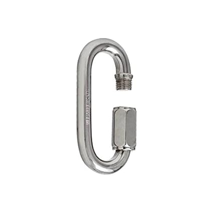
The radiator is suspended from the underside of the bus with chains: one on each corner. The top of the chain is attached to an eye-hook that is mounted to the frame just under the floor. The chain and eye hook are connected with a thread-closed carabiner. The same combination is at the bottom of the chain, with an eye hook at each corner and a threaded carabiner attached to it. In between is a short stretch (3 or 4 links) of high-test chain. To remove the radiator from the bus, I slid my orange floor jack under the front rail of the radiator frame and lifted the unit until there was sufficient slack in the chain for the bottom link to slide out from the threaded carabiner. Once free, I lowered the front down, and shifted to the driver-side rear corner and then last the passenger side (I was lying on the passenger side so this order kept things within my sight and reach). Once the radiator and frame were on the ground, I slid them to the driver side so I could pull it out, and took the whole operation into the garage.... just as the rain started.

Radiator Off-Frame
about to remove the fans
Once in the garage, I needed to get all the frame bits and the fans taken off the old radiator. The frame was held on with 10mm screws, 4 on each end  (2 top, 2 bottom). Once removed, the frame and cowling fell away.

Each fan was held on with 4 one-use-only custom zip-ties. On the bottom end was a plastic square that crudely fit into a spot on the bottom of the fan. Connected to that is a zip-tie-like plastic stick that fits through a foam bit, the radiator fins, another foam bit and then another plastic square that clicks along the zip-tie. This last bit is what holds the zip-tie tight. To remove, I cut the custom zip-tie off with wire-cutters, retaining all of the pieces. I had thought that I could drill a hole through the bottom plastic square, and re-use all the rest (except the zip-tie stick part) by using a basic zip-tie. I didn't drill or reuse that bottom plastic bit, but I'll get into that during the re-assembly.

Like so many of my topics, this is too big to fit into one post, so I'll continue this later on. At this point, the old radiator is completely removed and stripped bare. Thanks, as always, for following along,

Wednesday, May 23, 2012

Zoom zoom

It seems that I've been gone long enough for the blogger format to have changed.  Apologies to my regular readers for both my delay and for any weirdness caused by the new blogger interface.  It'll be a basic update today, just touching on bus stuff.

Daily Driving
The ol' bus and I have been a tight-pair the last few weeks.  I've been driving him to work and back pretty much every day.  I've noticed a few things that are curious, but not necessarily alarming.  First, the coolant level continues to drop, but I can't spot a leak.  Also, the pressure (or is it vacuum?) build-up is so pure and strong that after a drive the coolant bottle is nearly empty.  When I remove the cap of the fill-bottle, coolant splashes back in all the way to the full line.  Crazy.  So, I hear the low-coolant alarm in the donor dash, but it doesn't necessarily mean I'm low on coolant... I really over-filled the bottle this morning.  I'll post what happens.
Second, there's an oil leak.  I don't know where it is, but the bus definitely leaves his mark when I park him. I think the oil line to or from the turbo could be it, or its the oil cooler or maybe the underside of the oil filter housing.  Regardless, I'll find a dry day next weekend and tighten everything.  I was just under there last weekend re-tightening all the coolant line hose clamps.  There's always something, but that's part of owning a 40 year old car.

Acceleration Interruption
fixed and re-installing
On the way home from work on Friday May 11th, I had a breakdown in the left-hand progress (not turn) lane during rush-hour.  The accelerator suddenly dropped to the floor and I was rolling without throttle control.  The RPM's dropped to 900, so I quickly scanned the traffic on Hall Blvd (in Beaverton).  I was unable to slide right, so I took a left turn into an apartment complex parking lot through the oncoming traffic.  Sketch.  I removed the front belly pan and discovered that my hack-awful welding job on the accelerator resistor bracket (see Accelerating Slowly) had failed.  Dandy.  With my welder deep in storage, getting this fixed could have been a real time killer.  Fortunately, Boo has a local mechanic guy (Johnny) who can do small welding repairs, so I asked him to do it.  Less than an hour (and only $15) after I gave it to him, the weld was done and the whole thing was painted.  I can''t find a business name for Johnny's garage, but the location is (9085 SW Beaverton Hillsdale Highway, Beaverton, Oregon).  Great guy.  Talk your ear-off, if you let him, but he'll fix your car for a fair price.

Since I've neglected the blog a bit, I'll post again in a couple of days covering snow and personal experiences.... and, of course, another bus conundrum. :)  As always, thanks for following along, and another apology for my blog negligence.

Saturday, December 26, 2009

Radiator test-fitted

Lots of stuff going on. First off, I got a request to quote from my blog, but the requester didn't leave me an email address or a way to contact him/her. If you want to quote from here, that's totally fine, but please leave a link to the original post when you do. Anyway, today's post covers the progress over the last 10 days. I got the holes drilled, the radiator test-hung and started working on the radiator cowl / shroud.

Drillin' holes
The 1972 Westfalia is a little unusual in how the underside is arranged. Unlike the later years, there are belly pans along the sides, running from front to rear wheel between the mid rails and the edges. The center section between the rails is (mostly) exposed to the floor. Within this center space is where we're playing.
After first looking at off-setting the radiator to the driver side of that middle space, I discovered that I couldn't make it fit. Between the tubes that carry the emergency cables,the clutch cable tube, the accelerator tube, etc, there's a lot of junk in there. I was only able to get it up high enough in the center, so after some wrestling, I marked spots with some chalk and bored 1/4" holes in the rear beam. The picture here shows the right side hole.

Chain of Fools
I tried to hang the radiator to the holes I drilled, but I had to reverse the brackets to make a test fit happen. I want the holes to be parallel to the floor and had initially thought that they would be much closer to the floor, but the thickness of the drill made that impossible. I discovered, after I got the brackets reversed, that I had to flip the radiator over because of junk tubes blocked access to the coolant inlet / outlets. Argh. So, now the inlet / outlet point down as does the temperature sensor on the front. This is the orientation that TurboBus uses, and he doesn't have issues with air in the system (my biggest concern with the in/out pointing down).
I was able to get the rear end suspended from the holes with the use of simple eye-hooks, and a few links of 600lb-test chain. For the front end, I was able to use a couple of holes that were already in the cross-beam. Each is next to a hole that is used by the emergency brake cables. The picture here shows the eye hook / washer / nut combination that I used. Suspended from that eye hook is 8" of chain to the front edge of the radiator bracket. The net resulting install leaves the front lip just 4" below the belly pans. That's better than I planned, in terms of clearance, but I'll be copying the TurboBus model for "scraping" air with a down-pointing lip. I think his install grabs as much air as hanging the radiator, but without the risks.
The picture to the right, here, shows the test fit hanging by the chain. I am able to move the radiator a few inches side to side and slightly front to back. In theory, this should help prevent damage to the radiator if something pops up. Since the front lip is now only 4 inches below the belly, the front beam and front axle are both lower to the ground.

Cowling Corner

After the clearance picture above was taken, I grabbed a cardboard box and started cutting a template for the cowling. It took a few times of test fitting, but I was able to make a decent template that worked for both sides. At least it seems that way. From the template, I marked cut lines on sheets of HVAC zinc-coated steel. Some quick work with some tin snips, and then back to test fitting. The picture to the right, here, shows one side cut, riveted together and in-place. I was able to get to the same point with the other side, but I didn't get a picture of it.

Next...
I'll be finishing up the cowling / shroud next. The riveted steel sides need to be bolted to the radiator brackets (bolts so they can be removed for maintenance). Then, I'll be test-fitting the radiator again. If it fits well, I'll run some kind of closed-cell foam insulation along the top of the shroud - to reduce the possibility of the edge cutting one of the junk tubes as well as reduce the air leakage over the top. After that, the cabin heater will get installed and routed, and the coolant lines will be run. Lots left to do just on the coolant system, but I can feel the wheels moving. I should get more time to work this next week. We'll see.

pictures:
top - drilled hole for rear mount.
middle top - eye hooks with fender washers, lock washers and nuts for front body-side mount
middle bottom - radiator hanging on mounts
bottom - left-side shroud fab'd, in-place, ready for bolting to bracket

Monday, November 23, 2009

Radiator mounting planned

I was fortunate to get a couple of hours on Sunday with limited distraction, so I rolled under the bus between showers and I believe i have a plan for mounting the radiator under the bus. I ran out to Lowes, got a bunch of hardware, and started what I believe to be the final run on the brackets before installing this beast. Most of today's post will deal with that. I have no further news about Tom or Marianne. My wife will be traveling to visit with them in a few weeks, so she'll dig up what's really going on when she's there.

Concerns
One of my lingering concerns about mounting a radidator under the bus is that it will be subjected to road debris abuse. Beyond just simple plastic bags, and gravel, there can be large obstacles in the road. I've seen mattresses, sheet rock, lumber, a ladder, etc, all in the last year on the Oregon highways. Add to that the ice and snow that we got last winter, where my Jetta was getting high-centered by the mid-road snow pack, and I think the concerns are justifiable. I have looked at many designs by different people, and they seem to fall into 2 categories: avoidance and strength.

Avoidance
The under-mount radiator designs that follow this pattern are purposely placed as flat as possible, and as close to the floor of the bus as possible. These achieve some degree of safety because the debris can't really get to them. The downside of this design is that the air can't get there naturally either so any cooling is done exclusively by fans. This puts considerable pressure on the system working correctly, leaving little margin for error for a failed fan. Some kind of fan monitoring should be used to indicate when the fans are on / off at the dashboard so the driver can know when the fan(s) has failed.

Strength
The under-mount radiator designs that follow this pattern are angled to catch the air, and have a cage of sorts around the radiator. This cage deflects debris from getting to the radiator, in theory. I would think that there is the possibility of high-centering or having the entire thing ripped off by passing debris, if the debris is something like a tree stump or some other non-movable object. These do have the benefit of naturally grabbing some air on its way by, so they can operate with some success if a fan(s) fails.

Flexibility
This is the pattern that I'm going to try. It is a take on the strength pattern, but allows for travel within the mounting so that the radiator mount can partially absorb, and partially avoid debris. This pattern should allow for natural air passage and the use of fans like the "strength" pattern, but with the ability to move up and down if a tree stump or other immovable object is traversed.

Implementation
First, I made the bracket relatively simply - it is just a simple "c" wrapping each of the 4 mount points on the radiator. These "c" wrappers then tied into one of 3 brackets - one for the front and 1 for each of the 2 rear. The front is a basic square tube the should assist in the strength of the front bracket while partially obstructing the temperature sensor from direct contact by flying debris. I covered this in previous postings.

To these brackets, I have attached eye-hooks. These eye hooks will connect, through chain, to eye-hooks that are connected to the cross-members under the belly of the bus (the point at the cross-member will be re-enforced with some extra steel). This chain will add the flexibility to move. To prevent the radiator from bouncing up into the floor of the bus, I will add a rubber travel-stop (think snubber from the front end). I will be able to vary the depth of the angle of the front end by adding or removing chain links. I have selected chain and single-links that can handle up to 450 pounds. Anything less seemed too thin and anything more seemed excessive.

Protection
Across the front bracket, I will attach a larger round pipe (like a 16" stretch of fencepost). This will serve as a bumper that will absorb the initial contact with the immovable object and cause the front lip to bounce up - at least that's the theory. Behind the post, I'll put in a security screen style grid to prevent larger rocks from getting past and into the radiator area.

Shrouding
Last, surrounding the floating radiator, I will put a small cowling / shroud. This will help guide the air to the radiator and keep the rad-heated air from recirculating when at a dead stop. This shroud won't be more than a half-dozen inches tall. If it were much taller, it would prevent the movement that the chain is allowing. If I can figure out a clever way, I'll curve the shroud so it rounds off at the top. This would allow the shroud to be taller. Regardless, it needs to be removable so I can get to the chain for maintenance.

That's it for today. I was able to get started on the eye-hooks, but I ran out of bolt-nuts, and daylight. I need to stop at the hardward store for lock washers and nuts. I doubt I'll have much more time before Thanksgiving to work on Hapy. I may not get any time on him for another week, actually, so, I won't post until after the holiday. Happy Thanksgiving, and thanks for reading.

Pictures:
top - the rear brackets with the eye-hooks attached. The long eye-hooks will go into the thick cross member in front of the transaxle
bottom - the front bracket with the long eye-hooks attached. These will be connected via a chain to one of the shorter cross members (which will be re-enforced / backed with some steel at the mount point)

Thursday, November 19, 2009

rad brackets continue

There's not much to add this time. I didn't get much time on the project these last few days, but I was able ot get a little bit further on the radiator bracket. I also have an update on my son's H1N1.

Radiator Bracket I finished the last of the 4 separate brackets. It went together like its twin on the front. After that, I put a bit of square-tubing across the front. After taking some measurements, and messing around with Google Sketchup, I have a working model of the underside of the bus. From this, I can conclude that I will have about 5-1/2" above the frame rail to play with. If I don't want more than 5 inches of drop on the front end, that gives less than 9 inches (after removing the thickness of the radiator) of possible exposure to air flow. I'll be getting under the bus this weekend, time and weather permitting. I hope to first figure out what to mount the front end to. Then, I'll start considering how I'll do that. I have a few ideas....

Front End Tie-In Ideas
First, there's the obvious bar across the beams and a couple of vertical-ish bars coming from the front of the radiator up to that cross-bar. Figure I tie-in some kind of rubber bit to absorb the vibration and torque-action on the body.
Second, I could put shorter vertical-ish bars up from the rad and connect to a cross bar (or eye-loops) with a short stretch of cable. This would make the pitch variable, so I could experiment a little.

Where Go Fans?
I could put fans under the radiator in a pull configuration. This seems to be the common thinking for best cooling, but wouldn't any water that passes through the radiator potentially get into the motor? I'm thinking that any time the fans would be in that condition, they would probably be turning on with some regularity, but its still something to think about.
Maybe the fans go on top in a push configuration. Then, any road debris could bounce up and damage a fan. Of course, if the fans weren't there, that debris would have damaged the radiator, so there will have to be some kind of security screening to protect the top of the radiator anyway.

Shroud Cowl
The picture that I linked in an earlier posting didn't have any shrouding at all. I don't know where his bus lives, so maybe it doesn't get very hot. I think I want at least some cowling on the sides and rear to prevent rad-heated air to re-flow through. In both of the design options above there would be a vertical-ish riser at the front on both corners. I'd need something at the rear to tie into. I'll have to give that some thought. Maybe it would just be a matter of careful cutting and I could re-use the shroud mount point that I'm using for the brackets.

Cedar's H1N1
Well, Cedar finished his battle with the flu and was back at school today. He came bounding downstairs all dressed and ready to roll after over-sleeping for a school day. He made it to school only 30 minutes after the late bell. Thanks for your words of concern. We have no updates on Marianne or Tom. I'll post as we learn what's going on.

pictures:
top - front rad bracket before attaching to radiator. That's a 12" ruler for perspective.
top middle - view along bracket from water sensor end of radiator.
bottom middle - bracket at water temp sensor. Note the sensor maintenance is not affected.
bottom - full view of radiator with front and rear brackets attached.