Showing posts with label luxury. Show all posts

Tuesday, June 7, 2022

Returning to Hapy Sounds - Part 3

I think I've touched pretty much every other part of Hapy's sound system this winter/spring, so I guess it's only right to finish it up with improving the head unit install. Of course, no stereo entry is complete without some fun with wiring, so there's some of that too. I am still pushing hard to have the bus ready for camping season. So, while this may seem to be a departure from the shortest trip to complete, we can't go camping or long-distance driving without sounds. In a way, the ability to easily hear the stereo was what triggered the noise containment project. We just gotta have it.

How Did We Get Here?
planning the cut
While I was working on getting sound deadener behind the original cardboard glove box, I decided to remove it for better access. I had already disconnected the luxury electrical set up for the electrical rough-in (See Ceiling Wire Rough In), so I simply unplugged the head unit that I had stashed in the glove box and pushed the plug out the hole I had bored in it. After emptying the remaining contents into a small cardboard box, I looked at the glove box. I discovered that the old cardboard box was holding on for dear life, and the removal of the support bar (Phillips screw on the underside of the glove box) did it in. The rear edge (front is front) that is pressed up against the dash had been all raggedy anyway, and once I started removing the box, that edge powdered off in chunks. So, I ordered one of those ABS plastic replacements. With the deteriorating original box in hand, I considered how I could more permanently mount the stereo when the new ABS box arrived. These were on back-order, like so many things these days, so I had to wait a while to complete this.

Solve the Head
mock-up with original box
I got a Metra Universal under-dash mounting kit (model 99-9000), and started fiddling with how that rectangular kit could fit into the rounded glove box. After several measure and test-fit attempts, it was fairly clear that hanging the stereo from the top of the box was not practical. The glove box was too shallow and the mounting kit too deep. I would have had to cut a large rectangle out of the rear of the glove box, and I'm not sure it would have fit right afterwards.

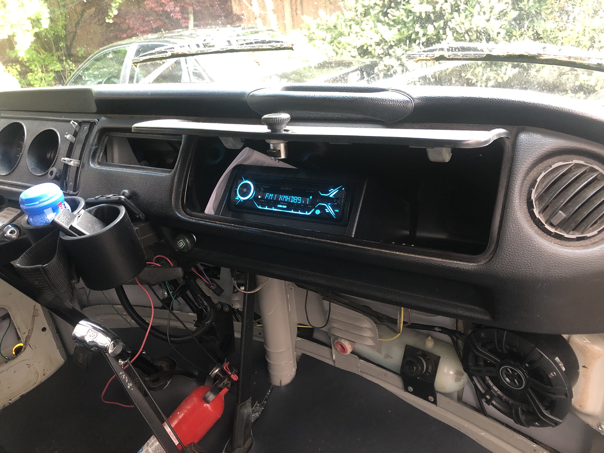
Back when I first got this head unit, I set the head unit in the glove box, on top of the molded shipping cardboard. It fit, and I could manage all of the buttons. Since hanging the box from above didn't work, I tried the kit upside down, mounting to the floor of the glove box. The kit was still too deep, but only by an inch or so. I measured, marked and cut an angle off the rear and it snugged right in. I confirmed that the stereo unit did not extend past the shortest point in the trimmed-down mount-box-thing. To mount the cut-down box to the glove box, things got interesting. I have demonstrated multiple times that I cannot manage to transfer measurements consistently. So, rather than swiss-cheese the underside of the box, I set the kit where I wanted it and marked two holes on the inside (blue tape, then a marker) of the box. I drilled out those 2 holes so I could align the rest of the box from below. I set the box such that the holes aligned and then held it in place with vice-grips while I marked the rest of the holes. Then, I drilled them out. Even then, the holes were not 100% perfect, so I expanded them where needed with a file. I added a hole at the rear of the glove box for the wiring pigtail with a hole saw and then attached the mounting kit with M3 bolts. That sentence took seconds to write, but the work took a couple of hours: tiny bolts + little finger room = patience needed.

Because, Wiring
marking holes
When I did the head unit the first time, I simply ran the power wire on the floor under the carpet. That was very Agile, demonstrated that having a stereo was a good thing, and that leveraging the luxury battery was a great call. So, since the stereo and the rest of the wiring in the bus was torn apart anyway, I changed the wire routing. Similar to the T12 front-to-back cable, I ran 2 sets of speaker cables and a power cable from behind the dash, down through the cable port behind the accelerator pedal and under the bus. I ran this collection of wiring along the frame and then found an existing factory hole (probably a drain hole) just inside of the passenger rear suspension up into the rock-n-roll bed. To keep things straight, the speaker wires were marked with tape (yellow-left, orange-right).

The yellow power wire was routed over to the driver side under the rock-n-roll bed and lightly tucked into place so it doesn't dangle into things and then integrated into the new fuse box (See Luxury Electrical Restored). Onto the speaker wires, I re-integrated the female wire connectors that I had before. One pair of two is under the rock-n-roll bed on the passenger side. Similar to the power wire, I tucked the wires under the rear edge of the bed floor so they stay out of the way. The other pair (recall there were 2 before) was sent through to the other side of the rock-n-roll bed up into rear of the formerly-fridge cabinet. Later, I may switch the female wire connectors to ports, but not today. At this point, I grabbed the floating remote rear speakers and plugged them in.
Back at the front of the bus, I integrated the various rear-speaker wires. Consider there's the pair that run up the A-pillar and to the rear over the sleeping area and the pair that now run under the bus to the rock-n-roll bed. The pair that run under the bus were the same as the pair that used to run along the floor. When I cut them, I marked them left-right. The pair that were sent up the A-pillar, however, were not. to figure out which one was which, I stripped one pair and clipped them together. Then, at the plug at the rear of the bus, I checked the plugs for continuity between the center-hole and the outer ring. One was infinite, the other was almost 0 resistance. 0 resistance is the winner, so I marked the end at the front with the same color tape (orange:right, IIRC) and then marked the other one. I spliced the remote speaker wire pairs together first, and then added the tiny wire from the stereo loom. I expect I will be adding an amp at some point, so I did not soldier them up. 

Putting it Together
note the mounting bolts
With the speaker wires integrated into the loom, the hard part was done. I spliced in ground and the yellow power wire and cleaned up the loom -to- front speaker connection. We were ready for install. The plastic glove box does not fit as easily into the dash as the old cardboard one does. I think it is a little larger, which really is fine. I needed and found a longer mounting screw (about an inch longer) for the support bar. To set the box in place, I found that suspending it in the support strap with the opening pointing up was most effective. Then, the box just tips into place. Since the box is bigger and less malleable, I focused on getting the bottom edge in the right spot, and let the top edge sit high. I sent the mounting screw home and the box doesn't wiggle at all.

I sent the wiring loom, the antenna cable and the wireless phone mic cord through the hole in the back of the glove box and plugged everything in. I took a quick glance at the fuse box and saw the tell-tale red LED telling me that I had a good circuit. Loving that fuse box feature. I set the stereo into the hole added a 10A fuse and fired up the local jazz station. After a few set-up steps on the stereo and burying the excess wire, the stereo is as complete as it needs to be for this Summer. 

So, the stereo is complete.... until I get a wild hair again to change it again. Like, wouldn't it be cool to have remote speaker plugs outside the slider so we can close the door without interrupting the music when set up for festivals or camping? Moments like this are when it is so obvious that this bus will never be done. There are always new ideas.

That's it for today. Thanks, as always, for following along-

Tuesday, May 31, 2022

Luxury Electrical Restored

As I work through the interior of the 1972 bus, I am learning that there are many layers to the electrical re-visit. I posted about the re-wire of the ceiling circuits (see Ceiling Wiring Rough-In). Today, I go over some of the other modifications I have been doing in the electrical space. I had the interior torn apart, so it seemed like a good opportunity to get after things before I put it all back together again. For example, the cushions have been removed from the rock-n-roll bed, and the cabinets have been emptied. 

Changing Tack
I am absolutely feeling time pressure, as the days get longer and camping season looms. So, I am shifting to getting things good 'nuf for Summer. What does that mean? I am setting aside the headliner. I am setting aside the carpet and the door card stuff. Instead, I am going to focus on getting Hapy operational enough for us to enjoy the Summer. The new reduced scope for the Spring includes the finish electrical (this post), completing the sound deadening (slider door and a few little bits here and there) and getting everything else that was pulled apart put back together. If I have any time opportunities pop up, I will do a little thing here or there so long as it doesn't impact our ability to take Hapy out for a spin or a camping trip.

Furnace Control Moved
Afterburner control
Recall the diesel furnace I added a couple years ago. When I did it, I added a custom computer-based thermostat, called Afterburner, hand-built by a guy in Australia. I had mounted the control unit to the side wall about where the 1979 Westfalia control panel traditionally sat. I decided that I did not need to see the thermostat all the time, and would prefer the less-cluttered look. Also, the LED panel glows whenever there is power (it doesn't have a sleep concept), so at night, it acts like a potentially unwelcome nightlight. I moved that control panel right next to that 1979 control panel: inside the rear cabinet. The wiring was readily available, and simply required another hole to be bored in the wood panel. The temperature probe, of course, needs to be in open space. I had previously routed it up along the C-pillar (between the mid-window and the rear window) and set it sort of hanging on the window frame. Obviously, that was temporary. I am not sure where I will put it now, but according to Ray, Mr. Afterburner, the sensor wire can be extended with CAT5 cable. The extension should work, but if I can avoid adding another variable, I will. Ultimately, I will solve this later. I did, however, run a CAT5 cable from the bottom of the B-pillar back to the furnace control so I could make the modification later, if I so choose.

I discovered during testing, however, that a couple of things are not working properly with the furnace. First, it test-fired okay, and it really pulled the voltage down on the luxury battery. I had forgotten about that, and the fact that I cut off the furnace wire back to the drive battery during the interior tear-out. I will need to upgrade the wiring to thicker gauge to see if that stops the heavy voltage drop, and then maybe re-plumb the wiring to the drive battery. Second, during the test run, it became obvious that the exhaust had become disconnected as exhaust started to appear inside the bus. That's bad. I will need to completely exhume the furnace and re-do the install to make sure there are no leaks. Last, there is something not right with the Afterburner controller. It no longer supports a web access point. So, it has all the other great stuff, but I can't start it remotely. In the end, the furnace will sit unused until I fix the exhaust... and the voltage drop. Maybe I'll figure out what's up with the Afterburner access point after that. Of course, it may be next spring by then.

New Fuse Box
new fuse box
I had been wrestling with a decision about the luxury fuse box for a while. I had been using a spare bay window bus fuse box. It worked well enough, but it was not perfect. It lacked a common positive post, some of the fuses had a common supply side and others did not, and there was a whole relay section that I didn't use. The fuses were the old-style fuses, not the newer bladed ones, and those old-style ones are becoming harder to source, and more expensive. Last, it is kind of big, almost 50 years old and the way I was using it was a hack that would fail. So, I bought a smaller 12-slot fuse box and a master circuit breaker / switch to put between the battery and the fuse box. Since many of the wires were being replaced, and the remaining were going to get at least touched as part of the routing, changing the fuse box was a small incremental increase in scope. I needed to remove the prior box for the noise contain efforts anyway, so I was halfway there already.

Doing the Doing
wire up in process
In the Ceiling Wiring Rough-In post, I described what color wire was going to be used for what. I ran or strung the wires to their destinations, and routed the other end down the driver-side (left) B-pillar, along the front edge of the middle window, under that window around the fridge-cabinet and left things pretty much in a heap right there. I started by completing the routing of the wires along the route that the solar collector wiring ran (See Hapy Gets Solar). I zip-tied the wires together and against the side of the bus and then solar wiring inside the fridge cabinet to hold them secure. Once I determined which fuse spots were to be used for which wire (see below), I mounted the new fuse-box onto the top of the wood box under the rock-n-roll bed which covers the old Westy rectifier.... basically in the same spot as the old one was before.

With the fuse-box in a fixed location, I could determine wire lengths and mount them up. In an ideal world, I would have used ring terminal wire-connectors on the wires. I could not find enough of them on hand, so I just used the bare wires. In classic Paulie Axiom form (See Light a Cigarette, Attract a Bus), I found them after I did this work so I will be slowly retrofitting them onto the wires. Anyway, once the wires were routed, trimmed and connected, I wrapped the bundle in one of those plastic wire tube things.

Fuse Layout
fuse wire color purpose
1 Grey Cab 12V Accessory Plug
2 Purple Cab Dome Light
3 Yellow Stereo
4 White 3-switch Dome Light
5 Pink PopTop Light / 1-switch Dome Light
6 Blue 3-position Westy Light
7 Yellow Furnace
8 Green Rock-n-Roll 12V Accessory Plug
9 Green Sleeping Area Dome Light
10 Orange Sleeping Area USB Chargers
11 OPEN OPEN
12 OPEN OPEN
 
Wait a Second...
wired up
The keen eye will notice that circuit #3 is wired up in the picture on the right, but isn't in the picture above it. Fuse #3 is the stereo. This is interesting only because of the gymnastics I executed to get it there. Before I started the noise project, the power lead for the stereo ran on the floor under the carpet. Yeah, that was not ideal, but it worked short-term. I ran a new power lead behind the dash and through the original wiring harness pass-thru hole in front of the accelerator pedal. From there, it runs along the inner edge of the passenger side frame rail and passes up under the rock-n-roll bed through what looks like a factory drain hole. A closer look at the rear edge of the wood floor will show the yellow wire running along behind / underneath. I didn't stop there, but that's another post I'll write up and post later.

Battery and Ground
Finishing up the circuit, I first confirmed that none of the wires I just hooked up to the fuse-box effectively ran to ground with the multi-meter. I returned the luxury battery to it's old location, and hooked up the ground cable to the same grounding bolt near the fridge cabinet under the seat. With the sound killer installed, it was a little harder to find.

ugly (for now) but functional
My last step was connecting the B+ or positive side. My old set up had many smaller gauge wires all wound together at the battery post. I used a very short stretch of 8 or 10ga wire to bridge from the positive post to a master switch, and then some more of it to bridge from the switch to the fuse-box. The wire was the thickest I had around. I will mind the overall amp usage, but this should not be an issue except for when the furnace first starts up. Even then, I do not expect much system stress. The master switch is a battery/fire-saver, basically, that will prevent more than 100A draw. I don't see this switch ever popping, but it is better to be safe than on fire. Based on the length of the wire, and my uncertainty about it's thickness, it is very possible that the wire will fail before the switch pops. Ultimately, I would need to have every circuit in use and have the furnace kick on to get close to even 50A. So, the switch becomes little more than a means to turn the whole system off.

Completing the Circuits
I had very little in terms of electricity consumers actually connected at this point. So, my ability to test was fairly limited and I only put fuses in the circuits as they were completed. Still, I was able to turn on the light by the front seats, and test the accessory plugs up front and by the rock-n-roll bed. All good. I checked continuity on the circuits which did not yet have a consumer, but I did not really expect any negative findings, and didn't have any. So, I started down the path of hooking up lights.

not as ugly. functional
I started with the light fixture over the sleeping area (pictured above). I used the mounting bolt for my ground, attaching a ring connector to the white wire, and leaving it inside the fixture. To the black and red wires, I connected female wire connectors. My method has been that the power-supply side wire would get a male connector, and continued that throughout. To the green (to fuse 8) and white (to the switch over the slider) supply-side wires I attached male wire connectors. I discovered, as I attempted to install the light fixture, that that 1/2" thick Mega Zorbe sound absorber was too thick for my bolts to reach the riv-nuts. I considered finding longer bolts, but concluded that the heat produced by the light fixture could have a negative impact on the foam, and chose instead to remove the foam where the fixture went. The fixture effectively recessed into the foam, which, I think will actually look better once the headliner goes in. It admittedly looks pretty trash right now. Once the fixture was mounted, I plugged in the wires, and Immediately, the red LED on the fuse-box next to fuse holder 8 lit. This told me that the circuit was good, and just needed a fuse. I popped in the fuse, and the light came on. Sweetness.

so many lighting choices
I followed this same path for the 3-position light over the window behind the driver seat (pictured above)... mounting bolt for ground, male female orientation, even plugging it all in to see the red LED. I needed to add a mounting plate behind the Mega Zorbe, but that was barely post-worthy. I cut out a small section, cut a rectangle of HVAC and screwed it to the bus. I set the fixture where I wanted it, marked and bored the holes. Easy-peasy.

I verified the pop top light at this point, and then shifted to the modified dome light (See Dome Light Mod to Trigger Other Lights). I had tried to mount this light earlier, and the mod wire broke off. I mentioned that in a comment on that original post, but I simply duplicated the effort with a thinner multi-stranded wire. On my repair version, I super glued the wire end down like before, but also added a 1-inch long stretch of superglue to adhere the insulation to the light housing. That bugger was not moving. I wrapped every bit of exposed metal (chair adapters, bits of relay, etc) with electrical tape so nothing would short out after I popped a couple of fuses. Once they were wrapped, and I could get the relay tucked in deep enough, I was able to settle the light fixture into place.

Testing the Lights
Once all of these circuits were completed, I cleaned up Hapy's interior and then hit it with the shop vac. Clean, and de-cluttered, Boo and I tested / played with the lights. The lights up front will work for checking a map or even reading a book. The original dome light, when turned on as a single creates plenty of light in the main cabin to see things on the floor, and even on top of the fridge cabinet. When the modified light circuit is turned on, the entire bus is well lit, from dash to tail gate. Since the rock-n-roll bed is not together, we could not test the reading lights for reading, but that test/play will be very soon.

With the new plan of just getting Hapy ready for the road, I do not feel the same pressure I did before. The lighting is functional, and I learned along the way that I needed to make modifications which would have been unpleasant after the headliner went in. Removing these fixtures for the headliner install will not be difficult either.

Thanks, as always, for following along-

Tuesday, June 9, 2020

Hapy Gets Solar

Last summer at the Newberry Event, I met a couple who were driving a pickup with a camper set up down the way from me. We got to talking about this and that as happens at music festivals. Conversation turned to camp set-ups and after a walk-thru of Hapy, they showed me their camper. I had seen newer camper-styles before, but I was really taken by their tiny solar panel. Today's post covers my transition from covet to install for Hapy.
Zamp Solar
I'll start with the panel that the Newberry Event couple had. It was a small, like, 1 foot square, portable panel (like this one - USP1005). It had an extending foot so you could prop it up independently, and had all of the conversion electronics attached to it. All you needed to do was run the supplied cable to your battery and clip it to the posts. Shazam, you have a trickle charge running to your battery. This all seemed to good to be true, so I took pictures of it to research later. They explained that they only camp in central Oregon, where the sun is seemingly ever-present, so a smaller panel completely suits their needs. I figured that we camp on the fog-socked Oregon coast as well as central Oregon, the Willamette Valley, etc so maybe we could use a larger one.

solar port
I did some research. I found that Zamp Solar is a small company based in Bend, Oregon. The reviews were great, and everything is manufactured here, so a purchase from them directly benefits the central Oregon economy. So, once my annual bonus arrived, I bought us one with the 1/3 I set aside for "fun" stuff. For the curious, the other 2/3 are split across saving for the future and paying off the past. It is a model I learned from some money-manager types 20 years ago. The thinking is that you're going to spend a little on stupid stuff anyway, so budget for it with 1/3 of your win-fall so you don't blow it all. It also creates some savings and eliminates some debt. Anyway, so I bought a larger one (USP1002). I also got an extension cable and a solar port. I probably could have gotten the wire harness, but I didn't realize they had it until after I had ordered a different install cable.

Install
controller
Like I said above, adding a solar panel to your luxury (or main) battery doesn't need to be complicated. I could just set up the panel and run the cable in through the slider, under the rock-n-roll bed to the battery. In all honesty, if I need to top-off the main battery, I will run a cable through the open engine hatch and alligator-clip to the posts. Since 99% of the battery usage when we are parked is consuming from the luxury battery, I wanted something a little cleaner.

To start, I soldered a 10 gauge red-black cable to the solar port (red to red, black to black, of course) and then heat-shrinked the connections. Now that I had a plug with 20' of cable attached, I could consider where to install it. I had thought about a few locations: inside the rear driver tire well, and under the belly pan on the passenger side. I resolved to putting it just behind the driver in the driver-side pan. I figured that if we were going to camp in a sunny spot, we will park so that the slider is on the shady side, so a port on the (non-slider) driver side made the most sense.

The backside of the solar port is rather thick, requiring a hole saw. Once bored, I threaded the bare-wire end of the cable up through the hole. I have an old hole in the floor of the bus where the '79 kitchen used to be so I pulled it the cable through by putting my arm into that hole. I ran the wire up out of that hole (I'll repair the larger hole one day) and then along the bottom of the old fridge cabinet where the furnace (see the Parking Heater series 1, 2, 3, 4 and 5) now lives.

From the front outer edge, the cable bends around and inside that cabinet, and then runs along the outer edge before turning towards the center of the bus at the rear, exiting where the power wire for the heater exits. The cable runs the same path around the rear edge of the base of the rock-n-roll bed to the luxury battery. At this point, I added a ring terminal on each cable.

With the wiring route defined, I returned to the belly pan. I pressed the solar port into the hole, and drilled a pilot hole for a metal screw. I oriented the port so the cap ran fore to aft with the little hinge facing the front of the bus. This seemed the best for debris flying around under there while driving. Once that first hole was screwed in, the solar port was fixed, so I could easily pop the other 3 holes and thread in corresponding screws.

Testing
DrivewayFest 2020
The ring terminals slid easily onto the luxury battery extra posts. I nutted them down, and then pulled out the solar panel. It ships with a thick semi-stiff zippered case to keep the glass safe. It unzips easily, and removes by the pull of the handle. The panel folds in half, held with a simple twist clasp. Once released, the hinges are stiff, so it doesn't flop open. Instead, you need to choose to open it. Inside are all of the controls, the 15' of cable and the flip-down feet. I set the panel in a sunny spot, and the controller started flashing me status that was basically: no battery connected, but able to charge. I connected the extension cable to the attached 15' and then connected the other end to the solar port. These cable only mate one way, so this is super simple. I walked around to the panel, and toggled through the controller screen. According to the panel, I was getting 13.6V, pushing amps (peaked just below 5A, just under 2A when cloudy), and charging the battery. I felt the wires inside the bus to make sure there was no temperature at all (I used the same gauge wire so there shouldn't have been) and there wasn't.

We set up the bus for what Boo and I referred to as DrivewayFest 2020, and left the panel running all weekend. We rolled music and spent the better part of 2 days lounging by the bus. With the solar panel installed and the furnace finished, we are now 100% ready for 4Peaks.... 2021.

Since that first test, I have set up the solar panel pretty much any time I'm in the driveway working on the cars or the yard, powering the stereo so we have tunes for the work. The battery charges up quickly and then the panel suspends pushing amps until it registers a need. This panel requires no input from me once it is set up. Perfect. I'd rather use my brain effort on other things. I highly recommend Zamp Solar; I do not get anything from that endorsement. I just like them.

Thanks as always, for following along.

Tuesday, August 13, 2019

Making Hapy Sounds (Part 3)

continuing from the Part 2 post about getting music into Hapy the wonderbus. When we left off, we had front speakers installed and rear speakers floating around in their own little speakerboxes. The wiring for all speakers had been routed back behind the dash. For the front speakers, the work was mostly a finished product. The rear speakers, though, were still very much in an experimental phase. Today, we wire up the head unit and complete the work.

Head Unit Physical Mounting
You know how when you swap out a big car stereo (a double-din) for a smaller one (single-din) you usually install one of those plastic boxes in the extra hole? Well, I had one of those box/bin things in my garage, and it had been there for a few years. So, I figured I'd put it to use. Shortly before we left for 4Peaks, I stuffed it into the radio hole in Hapy. On the drive and while at 4Peaks, we loved the extra storage spot. On the drive, it was where we put our phones. While we slept, we put valuables there. So, I didn't want to remove it to put in a stereo. Honestly, it was jammed in there so hard, I'm not sure I could get it out without destroying it anyway. AND, there was nothing in that are to physically attach a stereo to anyway. The old DarkStar stereo was held on from the front. Modern stereos need something to attach a rectangular channel to, and there was nothing there in the bus to bolt it to. So, I popped it into the glovebox instead. It still needs a real mounting, but for version 1, it sits on top of the packing cardboard it shipped in. Will it bounce around? Maybe. Could I break the stereo because I didn't mount it properly? Absolutely. Blindly moving forward, I drilled a 3/4" hole into the driver-side of the box, near the back, to run wires. With the glove box closed, it looks like the bus doesn't have a stereo... like it hasn't for the 15 years I've owned it.

Head Unit Wiring
In retrospect, I could have started here. I am not going to Should on myself (see Don't Should on Yourself), but if I ever have a virgin stereo install to do again, I will. Consider: the 2 most important bits for a stereo install to be successful is for a solid ground and a reliable source of 12V power. One could just solve those 2 wires and confirm the stereo works and your power is good before you do anything else. Wise advice for a future me. Anyway, for a ground, I doubled-up on a o-ring-d ground that was screwed into the air vent box. I verified that ground was good with a continuity test back to the negative post on the battery. For power, I tapped into an always-on circuit but it did not have enough juice to power the stereo. The radio acted like it didn't have any power, though I could read 12V at the plug. So... let me back up and then I'll get back to this.

I wired ground first. Always do ground first. Then, I took the various speaker wires and mated them with their respective colored wires coming out of the stereo plug. I intend to swap these into something more like the plug in Oliver, but this is fine for version one. Last, I tapped into a 12V source, hiding the wire, etc. Then we test fire.... nothing. This is where ideally I would have run ground, and 12V to prove it will power up before doing anything else.

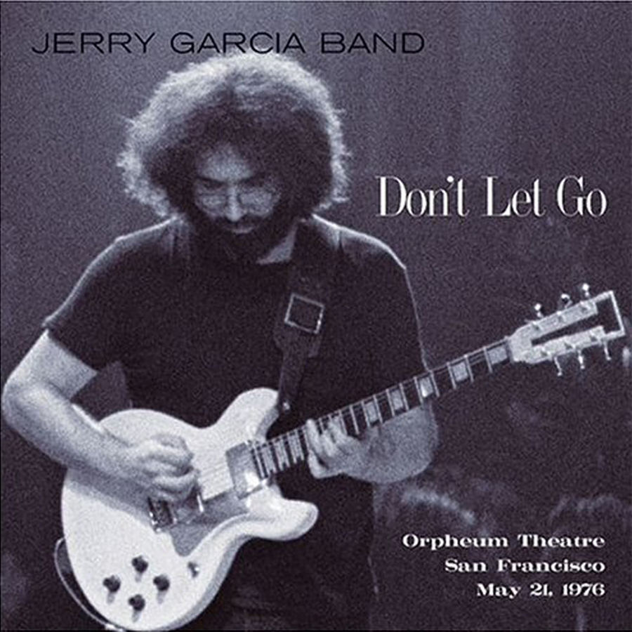
https://jerrygarcia.com/album/dont-let-go/
By now, it was getting late and I was getting tired and hungry. So, I ran a hot-lead from the luxury battery (our name for the deep cycle battery under the rock-n-roll bed that powers the lights and 12V sockets) to the back of the head unit strung across the lot couch, with a big coil bouncing between the front seats. It looked super-janky, but I needed to test whether the stereo would power up, and whether the speakers would respond. I plugged it in and heard the CD whir, so I knew I had power. So, I grabbed Boo and our copy of JGB's Don't Let Go CD for a test-listen before we both called it a day.

The smile produced by a JGB "Sugaree" is virtually a given, especially from the mid-70's era. That smile was compounded by hearing it coming from all around us in Hapy. "How loud does it get," Boo asked. She remembers our struggles to hear on the road as acutely as I do. Turning it louder and louder... it never distorted. Pure Jerry deliciousness pouring out of the speakers, hugging us with music until we were unable to talk over it. Yeah, that'll do.

12V Source Fixed
We shut things down, and I cleaned up my mess for the night. The following morning, I was back out there to run a 12V lead from the luxury fusebox to the stereo. This sounds simple, but it took quite some doing. I started at the glovebox, running a stiff 12ga wire through the hole and down behind the front "floor" vent. It runs below the TDI accelerator pedal (See Pedal on the Right) and under the rubber floor mat to the right edge of the driver seat pedestal. It runs along the right edge of that pedestal and under the old seat mounts for the 1972 Westy rear-facing seat, under slides for the lot-couch / middle-row seat and under the front edge of the rock-n-roll bed cabinet. It appears behind the cabinet near the corner by the refer-storage cabinet. I wired it into "fuse #12", protected with a 16amp fuse. I layered tape on top of the wire where it intersected with the lot couch slides to we don't accidentally catch that wire when putting the couch back in. That would be bad.

Once I had the new 12V supply line set, I re-tested. All good. I took the opportunity to tuck away some other errant wires up front. That's it for today. Version one is ready for some test drives and a festival or camping trip before we make any modifications or harden wiring to the rear. Thanks, as always, for following along-