Tuesday, March 29, 2022

Refresh the Luggage Tub

Over ten years ago, I purchased and installed the Riviera pop top, bed and luggage tub. In an Agile-like spirit, some of the steps I took were good enough to demonstrate the feature, but not great for the long haul. Today, I re-approach the luggage tub.
 
Why Now?
finished work
A logical question to ask when you take apart something that is functioning is why now? This is an especially good question since I am in the midst of a significant noise control effort already. Well, it was the noise control effort that brought this to my attention. When I was working on the cab ceiling, I discovered that some of the original 1972 Westfalia stuff was not keeping the ceiling sealed. To access the leaks, I had to remove the luggage tub, and things kind of grew from there.

Ceiling Repairs
I mentioned that there were ceiling seal issues. Consider that the hinges and the front-center latch for the original 1972 Westfalia pop-top attach to the top of the bus above the front seats. These are mounted by passing bolts through the ceiling and then threading into some flashing which have embedded nuts. The bolts had been removed, or broke off, but the leaks were coming from where the flashing/nut bit touched the ceiling. These had broken down over the last 10 years and were weeping. So, I removed the flashing, the nuts, and anything else remaining related to the old pop top mechanisms, leaving six holes.
 
cleaning under the luggage tub
In an ideal world, I would have used no-longer-with-us Travis' welder and repaired the holes the correct way with replacement steel cut into small circles. Unfortunately, when Travis passed, a grave-robbing vulture (Bob) swooped in, claimed he and Travis were "like brothers" (say it all deep and blubbery to get the effect), and took everything he could fit into his truck and trailer over multiple trips while my sister-in-law worked through her grief. Bob the vulture took all 4 of Travis' welders. Yes, that's right; all 4 of them (Travis was a pipe-fitter by trade so welded pretty much anything) and a TON of other things, like all of Travis' other tools, for example. Like the Grinch, Bob disappeared as quickly as he had appeared and cleaned out all of Travis' valuables. Just as he was a non-entity before Travis passed, no one has heard from him since. May you die alone, Bob; you are the worst. I was suspicious of you then, and deeply regret not honoring Travis' memory as you cleaned out his legacy. I digress, but suffice to say I do not have access to a welder anymore, so I solved in a more ShadeTree way.
 
heat shrink before/after
First, I closed up the holes from below with the Constrained Layered Dampener (CLD) since I was applying it anyway. This left small, shallow, circular indentations, about the size of a US dime (in diameter) in the top. I filled the indentations with FlexSeal. Once dry, I painted over the FlexSeal and the rest of the top with the same white Rustoleum. Of course, around this work, I removed the tub, cleaned the top (picture above-right shows how filthy it was), and addressed the surface rust with converter and then encapsulator, both from Eastwood. With the tin-top good enough for another 10 years, I shifted to the luggage tub.

Tub Cleanup
The luggage tub needed it's own help. The rack bars were starting to show some rust, and one of them had become disconnected at one end. 10 years ago, when I initially installed the tub, I quick painted it with the white Rustoleum and attached it to the top with 4 long wood-screws. I had completely forgotten I had done that, but it had held on without issue. To my surprise, all 4 screws threaded right out of the metal top when I went to remove the tub. These holes served as the starting point for the more robust mounting I did later.

doing the doing
With the tub now on the floor of my garage, I drilled out the rivets holding the bars to the fiberglass. Over the course of many hours, I sanded them down to bare metal, and got off most of the rust. What remained got the converter/encapsulator treatment and then some white Rustoleum. Unlike the bars, the metal supports that run from side-to-side were in perfect rust-free condition, after sanding off the paint. I chose to leave them unpainted, and polished them with steel-wool before shooting them with clear-coat instead. When I purchased the top and tub, one of the luggage cleats was missing. I chose to replace all of them with stainless steel cleats (footman loops) which I bolted (M3 Allen bolts) instead of rivet'd in place. Incredibly, the footman loops that I used to mount the big speaker box into Oliver, the 1978 MGB, were a perfect fit. While everything was apart, I hauled the tub outside and applied a fresh coat of white Rustoleum to the fiberglass tub. Once the paint was dry, I set the tub on some old carpet bits to protect the finish a little bit.
 
Before I bolted (rather than rivet'd) the now-rust-protected-and-white bars back to the tub (M4 hex bolts), I tried 3/4" inner-diameter clear PVC/Vinyl tubing onto the round part of the bar. I thought this might help the paint last a little longer as well as soften the rack for things placed onto it. Unfortunately, the tube is just a shade too loose. I did not want moisture to wick underneath, and the gaps at the ends just didn't look that great. So, I pulled that off and used 3/4" inner-diameter clear heat-shrink instead. I warmed it carefully with a propane torch, just enough to engage the shrink and have it snug up on the bar. The picture above on the right shows how well the heat shrink sealed the bars. Honestly, FlexSeal probably could have done the same thing.
riv-nut tool set

Keeping with the whole noise reduction thing, I added some Noico to the hidden inside of the tub. I figured that it would reduce the vibration noise a little bit. Similar to the effect of adding this stuff to metal, the sound from tapping on the fiberglass changed to a much deeper note after the Noico was added. There is no way to know if this helped at all, but it seemed at least a little logical. The addition of the Noico added maybe a couple of pounds to the luggage tub, but if the noise on the highway is meaningfully reduced, this could be a contributing factor. Something is increasing the noise once we get up above 50mph, and since the luggage tub is right above our heads, it is a reasonably assumed source.

The last thing I did before installing the tub, I added a white pinch-edging around the outer edge. Originally, the Riviera pop-top shipped with a white edging like this. When I purchased this top, it did not have one. I don't think it really does much other than dress the edge a little bit. I could reduce some vibration transmission into the roof from the wind-whip at higher speeds, though. Again, like with the addition of the Noico on the underside of the tub, I'll take every fraction of a decibel reduction I can get. For those thinking of doing this to their luggage tub, it took 15 feet of piping. I had purchased 30 feet, thinking that woudl be enough to do the luggage tub and the pop-top. Clearly my guestimates were way off. I'll need to get more to do the pop-top, and I have enough left over for someone else to do just their tub. 

Tub Install
parts-express foot
Of course, I did not want to return to 4 long wood-screws holding the top on. While that appeared to work for 10 years, I did not want to press my luck. In a traditional install, the ASI/Riviera folks would bore 4 holes into the top and weld nuts in place from the underside. The top install would consist of 1 bolt per corner from above, passing through a thick rubber puck into the welded-on nut. Again, I do not have access to a welder, so I could not exactly repeat the original design. I could, however, pop in riv-nuts. A riv-nut installs like a pop-rivet: using a squeeze gun that has a mandrel and riv-nut sized for the job, you put the riv-nut on the installed mandrel, set it through the hole and pop it like a rivet. For the rubber puck, I found 4 rubber feet at a stereo-supply place (parts-express) that are 1-1/2" tall by 1-1/2" across. These feet have a central hole through the center.
 
I drilled out the old mounting holes large enough for the M5 riv-nut to fit. I applied the riv-nut from below: Since the riv-nut has a flush side (side where it is installed from) and a sticks-out side, it would be better for the sticks-out side not to be pointing down towards my head. As you can see from the stock picture of the foot, one end is wide, allowing the sticks-out side of the riv-nut a ready-made home inside.
 
view with the edging
I thought I could counter the Riviera install, and I run M5 stainless steel bolts from inside the cab up through the stereo-supply feet. This did not work for a reason I could not determine. So, I followed the original model with the bolts heading down from above instead: bolt through a fender washer, then the tub, through the rubber foot and into the riv-nut. Fortunately, the bolts I had were long enough to reach the riv-nuts but not so long that they protrude past the flush-side.

This whole affair became an incredible time consumer that I did not plan for. Once I saw the holes, I had to solve. Of course, I did not have to repaint the tub/top, nor swap out the cleats, replace the pop-rivets with stainless hardware, etc. This finished product looks better, will work better and is set up for seasonal maintenance. Which prompts me to encourage you to consider when was the last time you removed any of the plastic bits off your ride to clean up accumulated organic material. Your paint, and perhaps the integrity of your ride, will thank you.

Well, that's it for today. Thanks, as always, for following along-

Tuesday, March 22, 2022

Noise Control Update

I started working on the sound abatement/control/contain effort in fits and starts over the last couple of months. Since I have been making some progress, I figured an update was due. I have only started the Constrained Layered Dampener (CLD). At some point I will be done with the CLD, and ready for the next layer. For more about my plan for noise control, see Hapy Noises Parts 1 and 2.

Sound Deadening
high-cost / high-value CLD
Sound deadening is slow-going stuff, even when you have time. The actual application of the CLD is fast and easy; getting access to the spots where you want to apply it is what takes a while. Some areas are virtually uncovered; like under the carpet in your trunk, the rear under the mattress of the camper bus is open bare steel. The metal gets cleaned with oil/grease remover, the largest square/rectangle of the highest quality deadener you can find is carefully applied and then you roll out any bubbles for a firm bond. In this way, the exposed steel was relatively quick work. I suggest you wear thin protective gloves because the edges of the foil layer can make tiny cuts in your fingers.

Accessing the Ceiling
To get to the largest sections of steel (the ceiling), I needed to remove the wood (Baltic Birch) headliner. The headliner is actually 4 distinct pieces: the rear, the front and 2 sides. Between the sections are channeled aluminum bits to hold the pieces together. Then, around the opening in the middle of the bus, a plastic pinch-surround holds the lip of the wood against the steel. The plastic pinch-surround removes with little effort: just grab and pull. In fact, getting this thing to stay put had been a bit of a challenge over the years. With some channel-lock pliers, tug on the aluminum channels, pulling towards the center of the bus, to remove them. With the channels and pinch thing gone, the rectangular piece over the sliding door fell right off. The one of the opposite side was held on by the '79 Westy interior 2-way light. Two screw removals later and the light and ceiling bit were free.
not quite done, but getting there

On Hapy, the rear section had been falling down for years, and I had resolved it long ago with self-tapping screws, through the metal ceiling. Recall, the westy was built on a "sunroof" bus model, so there are actually 2 ceilings (well, 3, if you count the Baltic Birch) with a gap between them where the sunroof would slide when open. Once I pulled the screws, the wood hung down in a familiar way. I simply helped what gravity had been doing by giving it a wiggle, and it fell onto the rear deck. This left the front section, which was quite snug. The internet instructions indicate that you simply need to remove the dome light and use that opening as a grip to pull the ceiling free. This did not work for Hapy, even after I removed the front shelf (See Sunshade to Shelf) I added, like, 6 years ago. Recall, the shelf was attached by re-using the sun-visor mounting points so it was a simple matter of removing some screws. With the shelf out of the way, I could get to the screws holding the 12V accessory plug, and then there were some very small screws along the front edge of the Baltic Birch which held the front lip snug against the front of the bus. After removing all the fasteners I could find, the ceiling still did not want to come down. I had to force it, and I accidentally split the driver side. I had no intention of reusing the old wood ceiling, but it would have been nice to give it to someone who is restoring theirs. Oh well.

Ceiling CLD
Once the front bit was down, I could see old-style fiberglass insulation had been installed between the drop ceiling and the steel, but only on the driver side. Perhaps the passenger side had been removed long ago. Regardless, I was not intending to keep it, so I pulled it down (wear gloves or you may get tiny fiberglass particles embedded in your skin. Ouch.), and scraped the glue residue off the metal with a putty knife. Similar to the rear floor, I cleaned and scraped and cleaned the metal in preparation for CLD. I used a combination of ResoNix (high cost / high-value) and the leftover Noico (cheap / lower value), hoping to maximize the vibration noise control. I may have overdone it, but I figured an extra pound of CLD might make a difference on the steel closest to my head.

rear half under top bunk
The ceiling in the rear had not been insulated nor had anything glued to it, so it was pristine metal. Still, it got the oil/grease cleaner treatment, and then multiple squares of ResoNix CLD. Recall that the sunroof model has 2 rear ceilings, and I had only addressed the bottom one at this point. The upper ceiling was much harder to get after. From above, it is covered with the floor of the Riviera-sourced upper bunk. From below, it has less than 2 inches of space between it and the lower ceiling. After mentally wrestling with how to deaden it, I decided to remove the plywood floor of the bed so I could apply material. There was simply no way to get good coverage 5 feet deep through a 2-inch tall gap.

The bed is supposed to be nailed down to the side rails with many tiny finish nails. In Hapy's case, I, uh... kinda didn't nail it down much. So, it would have been easy, had I not parked the bus where the pop-top would not open all the way. Instead, I could only get it halfway. So, I lifted the bed, pulled it as far forward as I could and then dealt with the noise suppression in 2 steps (rear half / front half). I took one extra step during the re-install, and added small squares of foam on top of the rails before setting the bed back in place. My thinking was that there would be less vibration and squeaking compared to the stock wood-on-wood. I will be adding sound absorbing material into the 2-inch tall cavity rather than on top, so I am hoping that I will not need to get under there again. Once I have confirmed that, I will send some thin screws through to hold the bed to the frame.

Exposed Metal
some easy-to-access steel
The last area, well, in terms of timing, this was actually my first, I addressed with CLD is the bare exposed steel around the bed along the sides. The keen eye will see that this is the Noico stuff. Yes, I did this area before I took the plunge on the ResoNix. Still, the tone of the tool-tap implies that the end result is less ring-y than without. Would the ResoNix had been more effective? Probably. Anyway, I mentally wrestled with applying material here at all because the rounded metal interior is part of the signature of an old bus. Arguably, so is the incredible racket you hear while driving. In fact, I used to drive by ear, listening for bad sounds from the original engine because the lack of instrumentation kind of forced me to. Anyway, the area below the window will ultimately be covered by a door/interior card. I intend to apply a headliner of some kind down to the tops of the cards, so the CLD you see in this picture will be hidden longer-term. 

Well, this is as far as I have gotten on the noise control stuff. Some of these steps were taken months ago, and others I just completed. That's just how life is these days: take many little steps and eventually you look around to discover that you have made some progress.

Thanks, as always, for following along-

Tuesday, March 15, 2022

VW Bus Cold Air Intake

Back when Hapy was getting regular long summer drives, I noticed that the engine bay would get pretty warm. Recall back to the Newberry trip report for example. So, I put together a cold air intake concept to drop the temp going into the turbo inlet. I really do not expect to notice much of a performance difference. While I understand a cold air intake can reduce intake temps, and improve engine performance by a handful of HP, I just don't think what I did will have that kind of impact. Still, it was fun to do.

For someone running the original engine, with the engine tins and surrounding foam in place, this modification makes absolutely no sense. The tins already effectively separate the hot side of the engine from the air intake. If you have lost your tins (or foam), and for some reason cannot replace them -or- you are running a modified engine where tins cannot be fitted, something like this might work for you too to keep the hot side from meaningfully impacting your intake air temperature. This whole bit is triggering memories of that old Burger King advertisement about keeping the hot side hot and the cool side cool.
 
Before I begin, today marks the Ides of March. I am not really sure how to recommend ways to celebrate that. Pay off your debts? Enjoy a celebration picnic with revelry and drinking? Wander out of town in an animal skin? Perhaps we can all just hope Putin will suffer Caesar's fate this day for the inhumanity he is visiting upon our Ukrainian friends. Whatever transpires, in a couple days, it will be St. Patrick's Day. So, I will just get some rest to prepare for that. Hopefully, we can tip a drink within 2 meters of dear friends to celebrate a post-pandemic Spring.

Orientation Thoughts
On topic, consider the VW bay window bus engine bay from the rear hatch (picture on the right is of a '68). Most to the rear on the left is an otherwise unused battery tray. Some folks (like late-bay Westy-drivers) have a luxury battery there to power the fridge when shore-power is not available. On Hapy, there are just a lot of wires, so it's actually not much to look at. The spare tire well hangs down towards the front, meeting the rear tire well. Above to the rear there is a tall open area that eventually reaches the finned ear behind the rear window. Running along the bottom edge, front-to-rear, there is a small lip or perhaps a pinch weld that's about half an inch tall. My thought: wall this in, and create a pass-through for my engine intake, isolating it from the heat generator (engine exhaust and the turbo). Keep the cool side cool.

Parts
My go-to for all things metal fabrication these days (at least for air movement) is HVAC flashing, and this is no exception: I started with some basic 20ga HVAC flashing that I had lying around ($0). Onto the air intake, I need to add a 90* turn ($14US from siliconeintakes.com) so the air filter which used to sit next to the rear end of the spare tire well can instead go into the new cavity. The last piece is pipe flashing (like this) which cost me about $18US to provide safe passage for the aluminum pipe through the HVAC. The air cleaner needs to fit through the hole left in the basic wall when the pipe flashing is removed, so getting one large enough for this purpose was important. I had some HVAC flashing lying around, but at the time I did this, a 4 foot by 3 foot sheet (common size) would have run about $20US. A smaller sheet would cost a little less, but not much. So, all-in this would cost around $50US plus your time.

Cleanup
paper model
I learned along the way that this wall idea is not as straight-forward as it looked. As I started trying to model with a large sheet of brown paper, I realized there were some wiring clean-up items left undone. I tidied up the wiring a little bit, and strung as much as I could into the upper rear corner where the fuel vent line passes into the new cavity, securing them together (and to the vent line) with a cable/zip-tie. Below this bundle of wires, at the rear-most bottom, a couple of wires need to pass as well, so that makes 2 gaps to manage. The front-to-back T-12 cable (See the Chasing the Hapy Electrical Gremlins posts for context) routes into the engine bay where the flat rear meets the upward angle of the rear tire well, so that's a third gap to seal. Last, the stock TDI engine management cable routes into the engine bay from under the center-point of the spare tire well, so that's 4 gaps. Had I planned for this when I did the wiring, I could have potentially cut this list in half, or even reduced it to one. I preferred to not revisit the electrical again this winter, after last winter's adventure. So, I made 4 distinct gaps for wires to pass through. I numbered them in the image of the paper model on the right, here.

Model with Paper
With the wiring bundled, I could start working on the wall... with a model. I started with brown packing paper. These days, so many things ship with large sheets of brown paper as the padding, and that stuff is nice and thick, and sometimes wide enough for things like this. It is also 100% recyclable (unlike the bubble wrap), so I'm doubly a fan. Anyway, I started with a basic measurement: 22 inches deep by 16 inches tall. Of course, I discovered that the hole is not square, and the 22 inch measurement is correct from the bottom of the rear wall to the point where the engine bay curves towards the fuel tank. The top is more than 24 inches from rear to top of fuel-tank compartment. Also, the section is not flat: the bottom curves slightly inwards while the top remains straight.
 
cardboard model 1
Then Cardboard
After a few rounds of test-fit, measure/cut and some added painter tape for strength, or for adding material for sizing, I arrived at an approximate paper model. I transferred the paper model to cardboard with a pencil using some tracing and some angle-square. Consider: the rear wall makes a 90* angle with both the top and the bottom, and (I thought) the rear wall is straight. The top run is straight, though I chose to cut some of the area away which would have been pressed against the spare tire well. I made this choice for 2 reasons: first, the vacuum control valves are mounted there, and I did not want to move them. Second, having a sheet of metal against metal like that would have created rattle noise I would have to solve. With my outline and wire bundle cut-outs defined, I cut the line with a razor blade and cleaned up the edges with scissors.

test-fitting a model
With this stiffer model, I performed another few rounds of test-fit, measure/cut until the cardboard wall completely covered the gap, the wire bundles easily fit through their respective gaps and the edges of the wall were clearly in a place where I could envision mounting. The final cardboard model, in-place in the picture on the right, also eliminated a large triangular shape from the lower front corner which would otherwise have set against the driver-side wheel well. Similar to the cut out from the spare tire well, having a large metal-to-metal contact area would create a vibration-noise opportunity. Looking back, this cardboard wall looked at least as good, if not better than, the final metal wall.

Then Model with Cardboard Again
The front and bottom have a lip I can easily attach to. The top and rear will need some kind thought and some creative drilling. One additional consideration: on the rear pillar, there are grounding points which cannot be disturbed. I decided to add a small tab on either side (above and below) to hold the new wall to the rear. The top will mount directly to the spare tire well for the front 2/3rds. The rearmost section of the top, will not get any treatment at all. I thought about it, and decided that there were already enough planned fastener points to hold the wall stable without adding another hole in the cabin floor. I transferred the cardboard model to another sheet of cardboard after a few repeated fit-attempts. I want to make sure the HVAC, when cut, will fit correctly. Last, I modeled mounting tabs with scrap cardboard and more blue painters tape so I would have them in the right place and the right size when I cut the HVAC. The picture above was taken before I added the mounting tabs to the model.

Plan the Intake Pass-Thru
note imperfect rear line
With the cardboard wall in place, that side of the engine bay looked considerably better... well, it hid what looked bad, anyway. Motivated, I planned the intake route based on the placement of the new 90* aluminum intake pipe. I made a rough cut in that general area of the cardboard wall and put it back in. The 90* pipe is too long on both ends. I needed to remove about 4 inches from the end that juts into the cavity, so there would be room for the air filter (7" tall from rubber grommet to chrome top) without it touching the side of the bus. The filter housing allows for up to 2 inches of pipe before it bottoms out, so there is some wiggle room for my cut on that end. Similarly, the engine-intake end of the 90* pipe needs to be shortened. Again, the silicone collar that attaches the new pipe to the air flow meter on the end of the intake allows for a couple of inches of play. I did not make the actual cuts to the pipe at this point, though.
 
The intake looked about right, so I added in the pipe flashing. I drew the edge of the flashing on the cardboard and then drew another set of lines 3/4-inch to the interior of the tracings. I cut the smaller square out of the cardboard, making a square that was about 6-1/2 inches per side. I tested that I could pass the air filter through that hole. Otherwise, maintenance of the air filter would require removing the entire wall. It fit, but barely, leaving about a quarter of an inch on each side (the widest part of the filter is 6-inch diameter).

Adjustments
HVAC test fit
I transferred the last model above to a sheet of HVAC, but I did not fit properly and had to do another round of cardboard before I was able to get a good HVAC design. The big barrier for me was the location of the vacuum valves (so probably not an issue for anyone else). Ultimately, I removed the valves that were no longer being used (anti-shudder and EGR), and moved the turbo controller to the rear mount. This freed up the front edge of the spare tire well. The second issue will appear for everyone who tries this: I thought that the rear inner wall was perpendicular to the floor and ceiling. It is not. Consider, the contour of the rear of the bus has a slight curve; the inner skin does as well. The picture just above on the right shows the deviation from pure vertical / 90* angle. That picture also shows on the bottom rear corner that the body panels do not have clean 90* transitions either. I cut off that little tab in future efforts. With these considerations, the models were working: showing me how to get to a viable wall.
 
Assemble
prepping the wall
For the second time, I transferred my cardboard model to HVAC flashing, complete with marks for mounting tabs. I cut the HVAC with my tin-snips, and formed the wire pass-thru's with pliers. For clarity, I marked the outline of the hole and then cut crossing lines through the center of that marked area. I folded the triangular bits of HVAC back upon itself to create the opening while also avoiding a sharp edge where the wire bundles would pass. With a hammer and dolly, I smashed the fold-back flat. By doubling the material at the openings, the wall was effectively stiffened; I had not anticipated, but will definitely appreciate that. For the upper rear wire pass-thru, I left a tang or tab nearest the rear wall that I could bend back into place, so the rear edge of gap #1 (visible in the pictures of the installed cardboard model) could get covered up once the wall was in place. Once I drilled the mounting holes in the tabs I set the wall in-place, marked the holes on the bus and drilled them out.

Pipe Flashing
wall installed
At this point, I considered how I would attach the pipe flashing to the HVAC. First, I transferred the square-ish hole from the cardboard model to the HVAC, and cut it. I need to be able to remove this section so I can clean the air filter. I drilled out 4 holes in the pipe flashing, one each per side, where the rubber had dimples for that purpose. I set the pipe flashing in place and marked the HVAC. These spots were within the folded-back HVAC, making the area thick enough to tap. Sweet! So, with a M4 (.75 thread-pitch) tap, I tapped the 4 holes in the HVAC. Into these threaded holes, I sent bolts from the cold-air side with thread-lock so these bolts will act like studs for the pipe flashing. The picture above on the right shows the studs through the HVAC.

Finishing
cold air intake
I moved the wall into place and secured it to the side of the bus with sheet metal screws. I had thought about tapping the holes and using bolts instead. The holes were too hard to access with a tap and I don't think this wall will be coming out with much frequency anyway. Even so, removing some sheet metal screws is not hard. With the wall in, I re-checked my measurements for cutting the aluminum pipe. Once verified with the permanent position of the pass-thru, I cut the pipe down. I pushed the shortened 90* aluminum pipe through the rubber collar and attached the air filter. I sent the air filter into the cavity, and maneuvered the not-filter-end of the 90* pipe through a connecting silicone collar to the rest of the intake. I set the pipe flashing against the HVAC and threaded on the 4 9mm nuts.
 
When I maintain the air filter, the process will be the same as this initial install: remove 4 nuts, loosen the hose clamp and remove the cold air intake assembly. After I clean the air filter, I would re-install by fitting the flashing atop the studs, finger on the nuts, get the pipes connected and then cinch down the nuts.

final install
Now, Hapy has a cold air intake, and the left side of the engine bay is no longer a complete visual downer. Instead, we have a nice clean wall and the engine will get colder air than it used to. This wall does have some small gaps, of course, so the air will not be as cool as it could have been. Perhaps I will circle back later with something on top of the wall to better seal the edges and pass-thru's. Longer term, I may apply a thermal layer onto the engine-bay side to help reduce temperatures even more. The picture on the right, here, shows it in its current (final) state, though a keen eye will see that I had not yet plugged in the AFM (air flow meter) when I took the picture.
 
This took quite a while to actually complete, having started before the 2021 winter holidays. I had other things going on, and this was a lower priority for sure. Also, there were multiple modeling cycles as I figured out the unique puzzles added to the driver side of the engine compartment from adding a TDI (and related vacuum control valves) to the mix.

That's it for today. Thanks, as always, for following along-

Tuesday, March 8, 2022

ToyoTruck Saga Continues

Earlier, I posted about a new arrival to the fleet (a 2006 Toyota Tacoma XRunner) and the smash into a post that followed. Today's post is the next step in that saga. 
 
Where Were We
front assembled
We got a $5k repair estimate, but insurance wouldn't pay (because the agent screwed up). So, I ordered the parts, and set about doing the work myself. With supply issues, it took an incredible amount of time for everything to arrive and the largest part, the hood, arrived with a big dent in it. I successfully replaced the fender, the 6-piece bumper and the fender liner. The radio antenna was so corroded, it could not be removed, so I had to replace it as well. The hood scoop was also degraded, so I ordered another one of those. I ended the post while waiting for supply chains to support a new hood, as well as deliver the replacement passenger-side flare and the hood scoop.

Hood Gets Hammered
I decided I could no longer wait for parts while the new truck occupied my best work bay (read: prevented me from working on Hapy). Besides, there was no way to know how long it would be before a new dent-free hood would be available again. So, I decided that I would do my best to get the old hood straight enough to fit without putting pressure on the new fender nor passenger front headlight. I started with my angle grinder, removing the remaining paint from the dented area. The leading edge of the hood had been crumpled under, against a lateral bulge that rests just rearward of that edge, along the underside of the hood (see the picture on the right). Since the lip was forced against that bulge, I was unable to get a tool between the two.
the damage from the underside

I started with the stud welder and a slide hammer kit I got from Harbor Freight when I started working on Zed (1978 280ZX). With the 2mm tip and studs, I was able to slowly move the leading edge of the hood away from the lateral bulge. After about 30 minutes, and a dozen studs, the edge had pulled back far enough for me to fit a dull chisel against the leading edge. By moving the chisel up and down the lip, giving it a few smacks every few millimeters, I was able to further shift the edge away.

Once the edge had been moved about a finger-width from the bulge, I started shifting from the hammer/chisel on the lip to the stud welder / slide hammer on the top of the hood and back. My hope was that I could get some of the original hood contour back while I got the edge pulled. I spent about 90 minutes in total before I felt that it was close enough to set on the truck to see how close I was getting.

Old Hood Finish Up
time to try fitting
I was satisfied enough with the hammer work to move the windshield washer hoses and the seal. I figured that if I was as close as I'd hoped, I wouldn't want to remove the hood simply to put these bits on it. Like so many things, the first time always takes longer than any subsequent attempt. I had the bits moved in minutes. The hood set quickly as well. Some cars have a great deal of adjust-ability when the hood is mounted, but this truck does not. Yes, there is some, but not more than an inch left-to-right at the front edge. I did not need much to get the hood evenly spaced between the fenders, though.

Similar to the hood removal, I set the front of the hood on my old plastic tool box so I could get to the hinge bolts. Before I slammed the hood down, I checked the height between the headlight and the hood edge on both the driver and passenger sides to make sure I wouldn't break the light housing. I found that I had over compensated with my hammering, but only by 1 or 2mm. I started a recurring cycle of identifying where the gap was, opening the hood, adjusting, and re-closing the hood. After 4 or 5 of these cycles, I was satisfied that it was good enough for now.

finished enough
The stud-welder took it's toll on the hood, however. Some of the studs were welded on so well, that my efforts with the slide hammer resulted in a small hole in the hood. I own that, though: I believe that I held the trigger a touch too long on those studs, setting too strong of a weld. Some of the other studs would not come off no matter how hard I hammered them. I ultimately had to cut them off, but there were bits left behind. So, I pulled out the angle grinder again, and ground the dent-damaged areas of the hood smooth to the touch. I shot the polished metal with some rattle-can automotive primer and then some basic black Rustoleum. The final-for-now product is pictured on the right. That passenger flare will be installed when it arrives. I haven't decided about the scoop insert.

Weeks Later, It's Done
At this point, I felt done enough with this project. Yes, some part of what I put together will need to come back apart for painting and when the passenger side wheel flare arrives, I will attach it. One day, I hope to have a better hood, and when that day comes I need to install the scoop insert as well. Since I would like to have the whole truck painted, I may take it to Beaverton Auto Body and have them do it. We already have a somewhat dated estimate, but at least we know what ballpark they are in. Of course, with inflation these days plus all the extra parts expenses I incurred, a re-shoot could be prohibitively expensive. Expensive enough to bring that work right back to my driveway to be shot in my home-made "booth" later. Oddly enough, the extra parts (scoop insert, p-side flare, and antenna) plus a second and future $500 hood still will still be less in parts than the Beaverton Auto Parts bid. And that number includes a hood I can't use, and I have not tried to sell off any parts I got and did not actually need.

That's it for today. I will return to the hood when I get one, and otherwise I will be focusing on Hapy again. Thanks, as always, for following along-

Tuesday, March 1, 2022

Enter ToyoTruck

Super long post today, and I still didn't get the project all the way done in one post. I did get most of the way, though, and I'll wrap it up next time. For today, I'll hit some background first, and then get into the adventure with this new-to-us truck. Since this started on Christmas 2021 and today is the first of March 2022, clearly this has been quite a saga. At the rate this is progressing, it will be competed mid-Summer.

Background - the setup
example image
When C returned for winter break from University, he left his car ('09 Subie) on campus. He needed a car while he was home so he could get to work, but we have a significantly reduced the operable fleet (sold Flash, sold K'Lack). So, we borrowed-as-a-prelude-to-buy Boo's sister Rose's Toyota Tacoma X-Runner. I am referring it ToyoTruck for now, though the interweb folks often call these "taco's". I suspect it will get a better name when it presents iteself. Rose has an older Ford truck that is getting a new engine swapped in, so this Toyota was kind of extra anyway. Clearly, having extra cars around is a family thing for us, and with the rehab we plan on doing on this house, having a pickup readily available for supply runs will be valuable. Anyway, C arrived home a few days before Christmas, just in time for some radical winter weather. We got snow, and ice, and more snow, some sleet, and melting followed by freezing. It was a full-blown winter stew. We let C use Boo's '09 Audi A4 (all wheel drive, newer M&S tires, etc) while Boo drove ToyoTruck. ToyoTruck is rear-wheel drive with mostly-worn-down summer highway tires. That would have been fine if it weren't for the winter weather. With Boo's new schedule, she has to report by 7:AM, which means leaving well before dawn, and right about at the overnight low temperature. This lead to a Christmas morning (yes, she worked Christmas morning) sliding-on-the-ice scenario which ended with the truck smacking a pole. The passenger fender, the bumper cover, passenger headlight, passenger fog light, the leading corner of the hood and some assorted little bits all were affected by the very low speed impact. The damage seemed minimal enough that Boo continued on to work. It wasn't until the next day that we got to access the damage in the daylight.

How Does that Insurance Commercial Go Again?
after post-smack
In the daylight, it looked pretty twisted, but it is mostly surface damage. I took a bunch of pictures and we tried to get a claim going with our insurance company. Turns out that insurance goes with the car, not the driver, so we needed to use Rose's insurance. We learned this while we were getting bids (~$5k) on the work. This is where insurance got interesting: even though Rose told Allstate she wanted "full coverage" the agent pulled a massive boner and failed to include collision (pays for damage to your car). How that meets the definition of "full coverage", I don't know, but I swear this feels like one of their ads... where they say the competitor will leave you hanging with a tagline like "if you don't have Allstate...". It appears that the Allstate ad is actually self-describing. Maybe their ad should be more like "if you let our agents do it, you're gonna get screwed". So, to sum this up: we borrowed a truck, slid into a pole causing ~$5k worth of damage and there's no insurance to fix it. Happy Christmas.

Paulie: Bodyman
Fast Times Camaro
To resolve, I tried my best Spicoli imitation: "Relax, all right? My old man is a television repairman, he's got this ultimate set of tools. I can fix it." Of course, the next scene in that movie (Fast Times at Ridgemont High) has that car, unrepaired, but tagged with Ridgemont sucks / Lincoln rules spray-paint. Instead of that, I'm actually going to repair it. I took the itemized bid and ordered all of the parts the body shop said needed to be replaced from CarParts.com. This cost about $1300US delivered. The bid had the parts for around $2k, so we are already ahead in the game. I will simply remove and install the parts I received, and hope I discover nothing else is wrong. The labor for the body panel removal/replacement was $900US. So, if I can get the truck back into one piece, I will have saved over half the bid. At $900US, using my usual price for my labor ($50/hr for simple math), I break even at 18 hours. On its surface, I think I can get way under that. I had a great experience with CarParts.com, by the way. The bumper cover was wrapped in thick plastic wrap inside a huge box and the fender was made-in-Taiwan steel double-wrapped in custom cardboard protecting it plus packing material between the wrapped fender and the box sides. The packaging of the headlights was equally protective. Some of the shipping, however, was spotty. We can credit GLS for losing and then claiming delivery of almost half the order. Ultimately, they got the parts to me, 2 weeks after they said they were delivered. That final delivery was curious in that the box appeared without a text nor email update, though I had been set up for both. Sneakily done, GLS.
 
Finally, with all the parts I had ordered in my garage, I was ready to get started. I had finally gotten the 2016 Sprinter seats installed into Hapy (See Hapy Seating Part 2), so I could shuffle vehicles around. Hapy went back into the driveway and ToyoTruck moved under the canopy so I can work out of the rain.

Body Panel Removals
2 replacement bits in
I started by removing the front grill, fog lights and bumper cover. Then, I pulled the headlights and removed the fender, leaving the hood for last. The grill is held to the top of the radiator support with 3 Phillips screws across the top. Down below, the electrical plugs for the fog lights are simple tab-lock plugs. Since I am replacing the fog-lights with the bumper, I left the old lights in the old bumper. For reference, just press the tabs and they wiggle out. With the plugs out, the fog lights can push through the bumper (after pressing inwards on the plastic retaining tabs). The bumper cover is held on with plastic push-on tabs across the top as well as a few from underneath. These pop free with a slotted screwdriver. Since they are 15+ years old, they will often fail on removal. There are also a few 10mm screws as well, all from below. The ends of the bumper cover tie into the inner wheel well plastic, but eventually, once the last fastener is free, the bumper just wiggles free.

I next removed the under-headlight trim bits. There is a small plastic push-on thing, like the ones that held the bumper cover, on the inside that attaches the trim bit to the headlight, but the rest of it just clicks into place... or out of place. The headlights are held in place with long Phillips-head bolts from the top, and 2 more on the sides (one connects to the lower radiator support, the other through the side of the fender). The lights unplug, but if they are stubborn, the bulbs which are not the main beam twist out with a 90* twist. Then, the plug can be wrestled free. The last big thing to remove is the fender itself. There are obvious bolts from above, but there is one hidden in the door jam near the top and one from the outside just rear of the wheel well. Of course, before final removal, the inner wheel well needs to be removed, and the antenna needs to be dealt with.
 
super-glued tabs on the flare 


The Inevitable Annoying Bits
The antenna and the inner wheel well skin are the worst part of this parts exchange. The antenna had become heavily oxidized and corroded, completely freezing the top nut. I ultimately broke-off the lower antenna mast so I could continue and ordered a top-to-bottom replacement, adding another $140US to the parts costs. Even on my garage floor, I was unable to separate the antenna bit from the bent fender.

The plastic inner wheel well is held in place by ribbed plastic clips along the inner edge and in a couple spots in the middle. Along the outer edge of the fender, the fender, the inner wheel well and the outer faring (flare) are held together with Phillips/10mm screws. When the truck hit the pole, the 3 top mount points along the outer faring / flare all broke. I did not realize that until I was removing things. Rather than order a replacement ($130US plus delivery), I collected the mounting ears and super-glued them back onto the flare as shown in the picture. Once the superglue had set up, the tabs did not wiggle. Since they broke off so cleanly, I could see their original pitch. So, I simply matched that and held the tabs for a 15 count as the glue set.

With the big parts out of the way, we can see where the little bits that Beaverton Auto Body suggested replacing. There is a small plastic bit that looks like a tiny fist with the hole in it that is Phillips-screwed to the fender. This holds the edge of the bumper in the right spot relative to the fender. There are 2 long thin brackets which support the top and bottom of the bumper cover (and lower leading edge of the fender) which were definitely tweaked. The small triangular bit that attaches to the passenger-side front (front is front) of the radiator support, extends forward to the other end of the long thin bracket, had a subtle twist to it. All of these attach with 10mm bolts, and you can see them installed in the picture above captioned "2 replacement bits in". They are the ones with big white labels.

Start Re-Assembly
windshield washer lines pre-removal
I started with the small bits: the triangular bracket first, and then the support bracket on the passenger side. I decided that the driver side bracket was untouched by the accident, so replacement was unnecessary. I swapped out the driver-side headlight next, re-using the original under-headlight trim bit since it was undamaged. Then, I tackled the fender. It is surprising how much faster install can be when you know where the fasteners go. I started with the 2 most difficult: the one on the bottom, heading straight in from the outside, and the one from inside the door. The bottom bolt is really only difficult because of all the extra lower body trim that appears on the XRunner needs to be loosened and held out of the way. I fear that I will need to completely remove all of the panels on that side because of all the dirt and sand I found in there when I took it apart. That dirt/sand may prevent a clean, tight install. Anyway, with the hard bolts in, I ran the bolts in along the top edge and then the front pair into the new bracket. I am not thrilled with the gap along the hood, but I will concern myself with that once the new hood goes on. It is possible that the hood got tweaked beyond just the small dent in the front corner.

After the fender, I installed the passenger-side headlight and the replacement under-trim. Other than cannibalize plastic fasteners from the bent and broken old body panels, this was as far as I could get at this point. I ordered a set of plastic snap-fasteners, but they had not arrived yet. Also, I had not planned for the antenna, so I could not completely button-up the fender and wheel well anyway. Yes, I could have stopped the post here...

The Hood
only disconnect needed
I was able to source everything, except the hood, from CarParts.com. For the hood, I turned to eBay, and got burned with a hood that arrived with a dent. My cursory inspection upon delivery did not detect that the passenger side had a couple of bashes in it under the cardboard wrap. I had checked the other 3 sides, so lesson learned here: completely unwrap the entire thing before you sign. I didn't know the pair of dents were there until I went to install it after installing the inner wheel skin down below, sadly. So, if I want a clean hood, I will order, pay, wait for and move-bits onto a second hood. FFS. Of course, with the supply chain issues around the world, there is a very small set of these hoods in the western US. In fact, according to the local Toyota dealer, there aren't any.
 
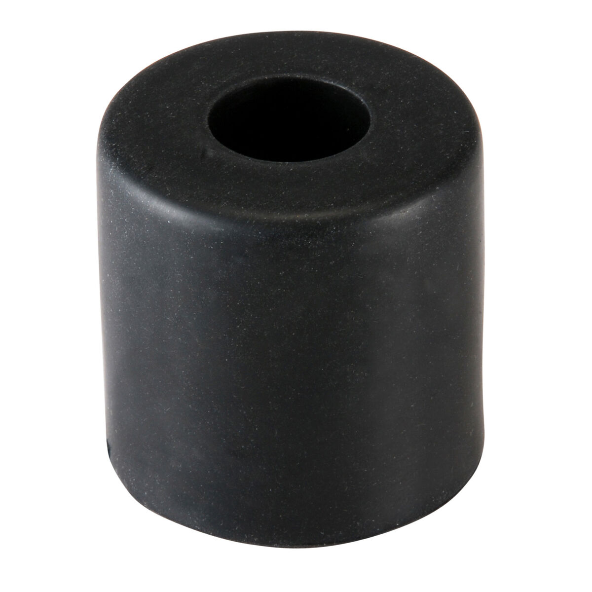
Obviously, the hood is held to the truck by 2 large hinges. Additionally, the windshield washer nozzles are in the hood. There are a few other things to transfer to the new hood, so I simply disconnected the washer hose and removed the bolts to free the hood. Then, I set the old hood next to the new hood in my garage. Piece by piece, with the puppy (Tuukka) watching, I moved the washer nozzles, bits of hose, the sealing rubber bits and the front rubber feet. Those feet are pretty interesting: they are solid rubber and thread in. You set the height of the closed hood by turning them clock or anti-clock wise. Very clever design.
 
There is a sealing strip that runs along the rear edge of the hood, held on by little plastic fasteners. I was able to free them without damaging them by using a door panel removal tool. I expected the washer nozzles and hose to the the hard part, with the scoop insert to be a breeze. It was the opposite, with the hose retainer plastic bits and the washer nozzles popping off with only a little difficulty, but remaining intact for reuse. These bits are held in place by little plastic barbs that need to be pinched in for removal. I used a slotted screwdriver, working one side and then the other until each one was free.

Hood Scoop Insert
The hood scoop insert, however, has seen better days. The mounting studs all backed out of the scoop, rather than allow the nuts to back off the stud. The 2 front studs would not separate from the old hood at all, and last, during install into the new hood, it cracked. This plastic is over 15 years old, and based on the damaged paint on the top of the vehicle and the sand I found in the wheel liner, I think we can conclude that this truck lived at the beach for a while, getting salt water on it while driving on the wet sand. I suspect it was parked outside mostly, as well, further accelerating the aging of the exterior. I will accordingly reset expectations for any other exterior bits I touch going forward.

I ordered a replacement hood scoop insert (another $140US for parts), and started considering doing a complete respray of this thing once the damage has been resolved. Of course, with the way I have to keep buying parts, that respray may need to wait a while. Meanwhile, I was in a holding pattern waiting for parts... and I was looking for a hood, again. Yes, I could have stopped the post here as well.

The Bumper
dry-fitting the bumper
The bumper cover / assembly is actually 6 distinct plastic bits: the main bumper cover, of course, a decorative center piece below the grill, 2 end pieces and 2 lower valences (split in the middle). Of these parts, we damaged 3: the main cover, the passenger-side valence and passenger-side end. All of these parts are held together with these blue wedge-like plastic clips. I was able to salvage all but one (which disappeared), which tells us just how slow moving the crash was. While I waited for parts, I re-assembled the bumper bits, excluding the decorative center. I had thought that I could paint the bumper as an assembly, but, I realized that I would need to take it all apart to install the decorative bit anyway, so I will be taking this all apart to shoot it. Of course, I put all this together mentally after I had put the bumper together physically. LOLs.

Still, by having the bumper bits together, I could dry-fit the front end together. Also, this reduced a big pile of parts in my small garage, and it helped me understand what bits I could sell-off, and which I still needed. For example, I discovered that there are little rubber strips between the main bumper cover and both the lower valences and the end bits. In the upper dry-fit picture, you can see the old valences on the ground below. A keen eye could see the rubber seals on top. I will be re-claiming those rubber bits before I dispose of the broken plastic parts. As you can also see. I have not removed the protective film from the lights yet; no need to tempt fate.

More Parts Arrive...
dry-fitting with the grille
After another week of waiting, things I ordered during the tear-down / re-assembly started to appear on my doorstep. So, I got back to it, starting with the antenna.
 
The antenna arrives with a stretch of cable that's about 1/2 a meter long with a pair of mounting clips already attached. This cable passes through the side wall and the fire wall up behind the glove box, and then runs up into the A pillar where it plugs into another cable. This seems like a strange design, but it's how it is. To access everything, the glove box needs to come out and the passenger grab handle needs to come out. There are a couple of plastic retaining clips that need to be popped (the OEM replacement antenna arrives with new clips) and then it is ready for removal. I attached a string to the end of the antenna cable and pulled it out through the side wall. I moved the string from the old cable to the new and pulled the string, bringing the cable along the original path.
 
The plastic tabs were in the right spots, and they popped in. The one in the rear of the picture below was a little difficult, but only because it is in a hard-to-get-to spot. I found by getting the front edge of the clip (front is front) first, allowed me to put pressure on the rear edge with a slotted screwdriver, snapping it home. Once the cable was in, the panels were installed in the order I removed them. The leading edge of the A-pillar trim inserts into a slot on the edge of the dash (seen in picture below) while the upper end has a tab that also fits into a slot: idiot-proof. The grab handle only fits into the A-pillar trim one way, and, because of the tabs, the mounting bolts align without effort. Inside the fender, the cable has a rubber grommet to seal the pass-thru hole. The top of the lower mast is then passed up into the hole in the fender and the lower end is bolted to a mounting tab with a 10mm bolt. After all the wrestling with German over-engineering, I really like this Japanese design. I feel like the Tacoma was built with owner maintenance in mind. I finished up the antenna on top of the fender with the outer rubber bit and nut and then threaded on the upper mast.

The Inner Wheel Well
installing antenna
All I had left was the inner wheel well, but I didn't explain the assembly of the rest of the bumper. As I mentioned earlier, I assembled the bumper, but I needed the bits to mount it. This was a straight-forward matter of using the plastic snap-clips where they belonged, and using the 10mm screws where they belonged. Since I failed to take quality pictures during tear-down, this was not as smooth as it could have been. Still, it all went together, leaving the passenger side wheel well. I purchased a replacement inner skin because I saw that the original had been damaged in the accident. The new liner was an exact match, and fitting it was not as terrible as installing on the old Jettas, but it was pretty close. These plastic liner things are the absolute worst. I did the outer edge last, simply because this edge also held the flare in place and I felt trying to juggle 3 things which were not in any way attached was at least one too many. The inner edge was straightforward: set the plastic skin where it is supposed to be and slam the plastic bit through the holes. The challenge for me was getting the square holes in the skin to consistently align with the square holes in the under-body.

With the skin now held in place by a handful of plastic bits, the outer edge was easier. I started at rear bottom and worked my way up. Again, having pictures would have been helpful so I could confidently set the skin / fender / flare stack correctly. Absent that, I just considered where water would go. So, I put the inner skin "outside" the fender along the rear edge for the first 3 fasteners (block water kick-up from the tires from getting inside fender) and at a cut-out transitioned it "inside" (so water drips from above don't run under the inner skin). At this point, I attempted to mount the fender flare. The super glue repair I described above failed almost immediately, so I shifted to the hood.... at which point I discovered the dents and my progress halted again.
 
I am going to halt this post here, and pick it up in another one. This has gotten very long, matching the saga, and the truck is still not in one piece. And, again, I'm waiting for parts.

Thanks for following along and more next time-