Showing posts with label battery. Show all posts

Wednesday, April 1, 2026

Returning to Oliver

The last week or so has been busy with lots of not-car stuff. We have had our young niece over a bunch while her mom had surgery on her wrist, and a bunch of social events. Of course, with the return of spring comes the return of recurring yardwork as well. So, I have not had the dedicated time for wrenching that I always seem to think will be available. I was able to get out to the shop for a few hours on Sunday, though. I focused on Oliver, the 1978 MGB, letting Hapy ('72 VW microbus) sit until Justin has his time with the injection pump in April. The rate at which the price of diesel fuel is climbing (passed $6US/gal around the corner), I may find that it costs more to fill his tank than to pay Justin for his time. That's totally upside-down. Anyway, back to wrenchin.
 
Voltage Gauge
remember Oliver?
I installed a Smith voltage gauge into Oliver where the original analog clock used to sit. The clock didn't really work very well, and it ate voltage from the battery when I let him sit for too long. This made the clock less accurate, leading me to pull the positive cable off the battery while not in use. This led to the clock being completely worthless. So, I pulled it out and swapped in the voltage gauge. It seemed like a valuable bit of info to have, but I had wired it into the "purple" or always-hot circuit. Like the clock, the voltage gauge slowly drained the battery down, albeit not as quickly. So, again, I pulled the positive cable while not driving. I changed that on Sunday.
 
Bearing in mind that any entry back into working on cars may not seem like a big deal to regular wrenchers, but I have really not done much car stuff in over a year. So, any steps taken are a big deal. Removing the gauge was simply unwinding the knurled nut holding the rear support and the gauge flopped forward out of the dash. I removed and taped-off the "purple" wire and started seeking a viable switched "green"source to tap into. Switched is available at a few spots, but I decided to run a dedicated line from the fuse box instead. I could say I did that to remove variables or variability in the voltage signal. The truth is that Oliver is parked so close to the side wall of the shop that getting in and under the dash was virtually impossible. I was not going to just start grabbing an unplugging things.
 
Smith voltage gauge
Running another wire is simple enough. I started at the gauge and worked my way behind the dash, center console, and glove box to the firewall pass-thru. From the pass through within the engine compartment, the bundle of wires run along the left fender to the fuse box. I tied the new wire into the existing green bundle and tested continuity with the multi-meter. Success! I installed the gauge, hooked up the battery and tested by turning the ignition to "run". The voltmeter slowly crept up and I could hear the fuel pump banging away. I recall that it used to get quieter with fuel in the pump. Satisfied, I turned off the key and looked for any other parasitic drain on the battery. The wires in the engine compartment need some containment. I am not liking the scattered multi-colored angel-hair look in the picture below right.
 
Battery Drain?
technicolor angel hair pasta wiring
Testing for a parasitic drain on your battery ought to be relatively straight-forward. Disconnect one cable. Set your multi-meter to test for Amps and then place one probe on the battery post and the other on the cable end. All 0's? Switch to milli-amps and try again. According to the internets, if the drain is less than 50mA, it is not enough to drain your battery. I got 0mA, which, honestly, I do not believe. I tested it multiple times, and even after cleaning the cable and the battery post, I still got 0mA. So, I checked voltage across the 2 posts (12.08V) and left the cables attached. I figured if the voltage drops overnight then my battery-drain test will be proven faulty. I have since tested the voltage the last 2 days. The battery loses 0.02V overnight, which I think I can attribute to the stereo. Regardless, I will need to add a float charger.
 
Red Rollie
new lock, locked
I have this old red Kennedy tool cabinet we call "Red Rollie". It houses a bunch of tools, and for most the nearly 20 years that I've owned it, the lock didn't work. Well, I didn't have a key for it. We got the cabinet at an estate sale without the key. Anyway, some tools were stolen from my next door neighbor's yard a few months ago, so that changed our vector regarding the shop. We were perfectly fine using it without doors, but I can't leave entire tool cabinets unlocked if thieves have found our quiet little neighborhood. While I think the theft next door was an inside job (they run a construction business out of their home), one can never be too sure. So, I found a lock that fits this old Kennedy cabinet (Kennedy 80403 High Security Tubular Lock), and replaced it.
 
Replacing one of these locks is actually easier than on newer cabinets. The lock is held on with a U-shaped tang that slides off to the side. The hard part is you can't see anything. With my fingers I was able to determine which direction the tang needed to slide to be removed (facing the cabinet, slide right), and then set a stubby slotted screw-driver against the lip of the tang. It only took one well-leveraged push to get the tang removed and the lock to pop out. To install, orient the lock so the little inner divot on the outside facing part of the lock where the key goes in is facing down (unlocked). Set the lock into the hole with one hand while guiding the locking rod into the rectangular hole on the back of the lock. Then, push the U-shaped tang in place to hold it.
 
Red Rollie
This worked great, and effectively locked the top 2 drawers. The 3rd drawer down, however, had been bent where the little hook pokes out the back. To remedy, I got a framing hammer and a 1/2" ratchet extension and beat on it until it was more-or-less flush with the rest of the rear of the drawer. For years I wondered why that drawer always set deeper into the cabinet than the others. Now I knew. Once the drawer had been persuaded, the drawer fronts lined up and that 3rd drawer locked as well.
 
Wrap
That's how I spent my Sunday afternoon. The shop still needs the 2 largest doors, but my tools are secure, and I am really starting to get comfortable in there. For example, there was a period of time while working on Oliver that the skies opened up and it started pouring rain. I never felt it. In fact, I could only hear it hitting the trees. The insulation on this shop stops the sound of rain on the steel roof. I absolutely did not expect that.
 
That's it for today. Next week is Easter, so I may not get out to the shop for much. I hope to put a little gas into Oliver and at least back him out to where I can give him a deep cleaning. 

Tuesday, June 7, 2022

Returning to Hapy Sounds - Part 3

I think I've touched pretty much every other part of Hapy's sound system this winter/spring, so I guess it's only right to finish it up with improving the head unit install. Of course, no stereo entry is complete without some fun with wiring, so there's some of that too. I am still pushing hard to have the bus ready for camping season. So, while this may seem to be a departure from the shortest trip to complete, we can't go camping or long-distance driving without sounds. In a way, the ability to easily hear the stereo was what triggered the noise containment project. We just gotta have it.

How Did We Get Here?
planning the cut
While I was working on getting sound deadener behind the original cardboard glove box, I decided to remove it for better access. I had already disconnected the luxury electrical set up for the electrical rough-in (See Ceiling Wire Rough In), so I simply unplugged the head unit that I had stashed in the glove box and pushed the plug out the hole I had bored in it. After emptying the remaining contents into a small cardboard box, I looked at the glove box. I discovered that the old cardboard box was holding on for dear life, and the removal of the support bar (Phillips screw on the underside of the glove box) did it in. The rear edge (front is front) that is pressed up against the dash had been all raggedy anyway, and once I started removing the box, that edge powdered off in chunks. So, I ordered one of those ABS plastic replacements. With the deteriorating original box in hand, I considered how I could more permanently mount the stereo when the new ABS box arrived. These were on back-order, like so many things these days, so I had to wait a while to complete this.

Solve the Head
mock-up with original box
I got a Metra Universal under-dash mounting kit (model 99-9000), and started fiddling with how that rectangular kit could fit into the rounded glove box. After several measure and test-fit attempts, it was fairly clear that hanging the stereo from the top of the box was not practical. The glove box was too shallow and the mounting kit too deep. I would have had to cut a large rectangle out of the rear of the glove box, and I'm not sure it would have fit right afterwards.

Back when I first got this head unit, I set the head unit in the glove box, on top of the molded shipping cardboard. It fit, and I could manage all of the buttons. Since hanging the box from above didn't work, I tried the kit upside down, mounting to the floor of the glove box. The kit was still too deep, but only by an inch or so. I measured, marked and cut an angle off the rear and it snugged right in. I confirmed that the stereo unit did not extend past the shortest point in the trimmed-down mount-box-thing. To mount the cut-down box to the glove box, things got interesting. I have demonstrated multiple times that I cannot manage to transfer measurements consistently. So, rather than swiss-cheese the underside of the box, I set the kit where I wanted it and marked two holes on the inside (blue tape, then a marker) of the box. I drilled out those 2 holes so I could align the rest of the box from below. I set the box such that the holes aligned and then held it in place with vice-grips while I marked the rest of the holes. Then, I drilled them out. Even then, the holes were not 100% perfect, so I expanded them where needed with a file. I added a hole at the rear of the glove box for the wiring pigtail with a hole saw and then attached the mounting kit with M3 bolts. That sentence took seconds to write, but the work took a couple of hours: tiny bolts + little finger room = patience needed.

Because, Wiring
marking holes
When I did the head unit the first time, I simply ran the power wire on the floor under the carpet. That was very Agile, demonstrated that having a stereo was a good thing, and that leveraging the luxury battery was a great call. So, since the stereo and the rest of the wiring in the bus was torn apart anyway, I changed the wire routing. Similar to the T12 front-to-back cable, I ran 2 sets of speaker cables and a power cable from behind the dash, down through the cable port behind the accelerator pedal and under the bus. I ran this collection of wiring along the frame and then found an existing factory hole (probably a drain hole) just inside of the passenger rear suspension up into the rock-n-roll bed. To keep things straight, the speaker wires were marked with tape (yellow-left, orange-right).

The yellow power wire was routed over to the driver side under the rock-n-roll bed and lightly tucked into place so it doesn't dangle into things and then integrated into the new fuse box (See Luxury Electrical Restored). Onto the speaker wires, I re-integrated the female wire connectors that I had before. One pair of two is under the rock-n-roll bed on the passenger side. Similar to the power wire, I tucked the wires under the rear edge of the bed floor so they stay out of the way. The other pair (recall there were 2 before) was sent through to the other side of the rock-n-roll bed up into rear of the formerly-fridge cabinet. Later, I may switch the female wire connectors to ports, but not today. At this point, I grabbed the floating remote rear speakers and plugged them in.

Back at the front of the bus, I integrated the various rear-speaker wires. Consider there's the pair that run up the A-pillar and to the rear over the sleeping area and the pair that now run under the bus to the rock-n-roll bed. The pair that run under the bus were the same as the pair that used to run along the floor. When I cut them, I marked them left-right. The pair that were sent up the A-pillar, however, were not. to figure out which one was which, I stripped one pair and clipped them together. Then, at the plug at the rear of the bus, I checked the plugs for continuity between the center-hole and the outer ring. One was infinite, the other was almost 0 resistance. 0 resistance is the winner, so I marked the end at the front with the same color tape (orange:right, IIRC) and then marked the other one. I spliced the remote speaker wire pairs together first, and then added the tiny wire from the stereo loom. I expect I will be adding an amp at some point, so I did not soldier them up. 

Putting it Together
note the mounting bolts
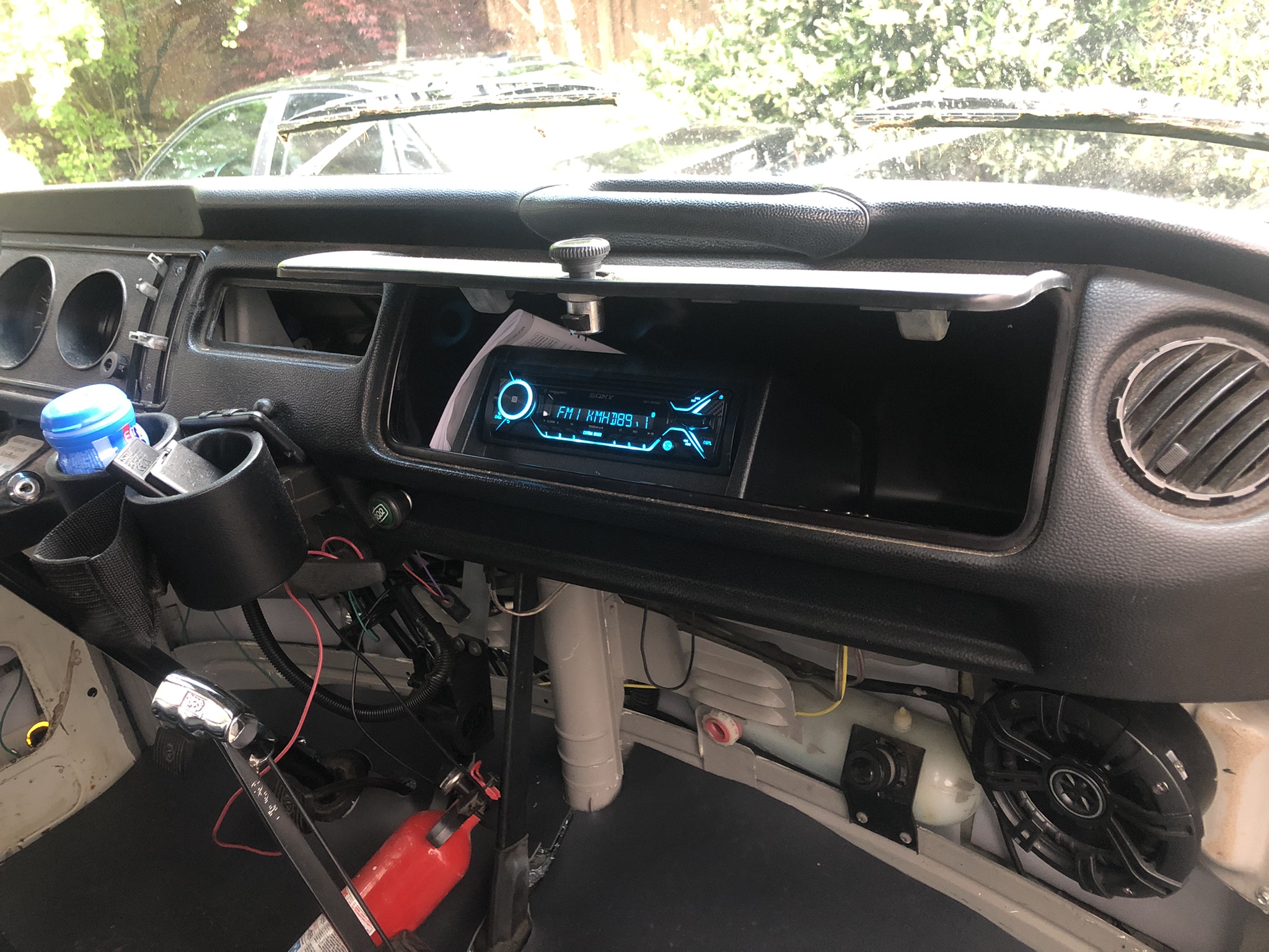
With the speaker wires integrated into the loom, the hard part was done. I spliced in ground and the yellow power wire and cleaned up the loom -to- front speaker connection. We were ready for install. The plastic glove box does not fit as easily into the dash as the old cardboard one does. I think it is a little larger, which really is fine. I needed and found a longer mounting screw (about an inch longer) for the support bar. To set the box in place, I found that suspending it in the support strap with the opening pointing up was most effective. Then, the box just tips into place. Since the box is bigger and less malleable, I focused on getting the bottom edge in the right spot, and let the top edge sit high. I sent the mounting screw home and the box doesn't wiggle at all.

I sent the wiring loom, the antenna cable and the wireless phone mic cord through the hole in the back of the glove box and plugged everything in. I took a quick glance at the fuse box and saw the tell-tale red LED telling me that I had a good circuit. Loving that fuse box feature. I set the stereo into the hole added a 10A fuse and fired up the local jazz station. After a few set-up steps on the stereo and burying the excess wire, the stereo is as complete as it needs to be for this Summer. 

So, the stereo is complete.... until I get a wild hair again to change it again. Like, wouldn't it be cool to have remote speaker plugs outside the slider so we can close the door without interrupting the music when set up for festivals or camping? Moments like this are when it is so obvious that this bus will never be done. There are always new ideas.

That's it for today. Thanks, as always, for following along-

Tuesday, May 31, 2022

Luxury Electrical Restored

As I work through the interior of the 1972 bus, I am learning that there are many layers to the electrical re-visit. I posted about the re-wire of the ceiling circuits (see Ceiling Wiring Rough-In). Today, I go over some of the other modifications I have been doing in the electrical space. I had the interior torn apart, so it seemed like a good opportunity to get after things before I put it all back together again. For example, the cushions have been removed from the rock-n-roll bed, and the cabinets have been emptied. 

Changing Tack
I am absolutely feeling time pressure, as the days get longer and camping season looms. So, I am shifting to getting things good 'nuf for Summer. What does that mean? I am setting aside the headliner. I am setting aside the carpet and the door card stuff. Instead, I am going to focus on getting Hapy operational enough for us to enjoy the Summer. The new reduced scope for the Spring includes the finish electrical (this post), completing the sound deadening (slider door and a few little bits here and there) and getting everything else that was pulled apart put back together. If I have any time opportunities pop up, I will do a little thing here or there so long as it doesn't impact our ability to take Hapy out for a spin or a camping trip.

Furnace Control Moved
Afterburner control
Recall the diesel furnace I added a couple years ago. When I did it, I added a custom computer-based thermostat, called Afterburner, hand-built by a guy in Australia. I had mounted the control unit to the side wall about where the 1979 Westfalia control panel traditionally sat. I decided that I did not need to see the thermostat all the time, and would prefer the less-cluttered look. Also, the LED panel glows whenever there is power (it doesn't have a sleep concept), so at night, it acts like a potentially unwelcome nightlight. I moved that control panel right next to that 1979 control panel: inside the rear cabinet. The wiring was readily available, and simply required another hole to be bored in the wood panel. The temperature probe, of course, needs to be in open space. I had previously routed it up along the C-pillar (between the mid-window and the rear window) and set it sort of hanging on the window frame. Obviously, that was temporary. I am not sure where I will put it now, but according to Ray, Mr. Afterburner, the sensor wire can be extended with CAT5 cable. The extension should work, but if I can avoid adding another variable, I will. Ultimately, I will solve this later. I did, however, run a CAT5 cable from the bottom of the B-pillar back to the furnace control so I could make the modification later, if I so choose.

I discovered during testing, however, that a couple of things are not working properly with the furnace. First, it test-fired okay, and it really pulled the voltage down on the luxury battery. I had forgotten about that, and the fact that I cut off the furnace wire back to the drive battery during the interior tear-out. I will need to upgrade the wiring to thicker gauge to see if that stops the heavy voltage drop, and then maybe re-plumb the wiring to the drive battery. Second, during the test run, it became obvious that the exhaust had become disconnected as exhaust started to appear inside the bus. That's bad. I will need to completely exhume the furnace and re-do the install to make sure there are no leaks. Last, there is something not right with the Afterburner controller. It no longer supports a web access point. So, it has all the other great stuff, but I can't start it remotely. In the end, the furnace will sit unused until I fix the exhaust... and the voltage drop. Maybe I'll figure out what's up with the Afterburner access point after that. Of course, it may be next spring by then.

New Fuse Box
new fuse box
I had been wrestling with a decision about the luxury fuse box for a while. I had been using a spare bay window bus fuse box. It worked well enough, but it was not perfect. It lacked a common positive post, some of the fuses had a common supply side and others did not, and there was a whole relay section that I didn't use. The fuses were the old-style fuses, not the newer bladed ones, and those old-style ones are becoming harder to source, and more expensive. Last, it is kind of big, almost 50 years old and the way I was using it was a hack that would fail. So, I bought a smaller 12-slot fuse box and a master circuit breaker / switch to put between the battery and the fuse box. Since many of the wires were being replaced, and the remaining were going to get at least touched as part of the routing, changing the fuse box was a small incremental increase in scope. I needed to remove the prior box for the noise contain efforts anyway, so I was halfway there already.

Doing the Doing
wire up in process
In the Ceiling Wiring Rough-In post, I described what color wire was going to be used for what. I ran or strung the wires to their destinations, and routed the other end down the driver-side (left) B-pillar, along the front edge of the middle window, under that window around the fridge-cabinet and left things pretty much in a heap right there. I started by completing the routing of the wires along the route that the solar collector wiring ran (See Hapy Gets Solar). I zip-tied the wires together and against the side of the bus and then solar wiring inside the fridge cabinet to hold them secure. Once I determined which fuse spots were to be used for which wire (see below), I mounted the new fuse-box onto the top of the wood box under the rock-n-roll bed which covers the old Westy rectifier.... basically in the same spot as the old one was before.

With the fuse-box in a fixed location, I could determine wire lengths and mount them up. In an ideal world, I would have used ring terminal wire-connectors on the wires. I could not find enough of them on hand, so I just used the bare wires. In classic Paulie Axiom form (See Light a Cigarette, Attract a Bus), I found them after I did this work so I will be slowly retrofitting them onto the wires. Anyway, once the wires were routed, trimmed and connected, I wrapped the bundle in one of those plastic wire tube things.

Fuse Layout
fuse wire color purpose
1 Grey Cab 12V Accessory Plug
2 Purple Cab Dome Light
3 Yellow Stereo
4 White 3-switch Dome Light
5 Pink PopTop Light / 1-switch Dome Light
6 Blue 3-position Westy Light
7 Yellow Furnace
8 Green Rock-n-Roll 12V Accessory Plug
9 Green Sleeping Area Dome Light
10 Orange Sleeping Area USB Chargers
11 OPEN OPEN
12 OPEN OPEN
 
Wait a Second...
wired up
The keen eye will notice that circuit #3 is wired up in the picture on the right, but isn't in the picture above it. Fuse #3 is the stereo. This is interesting only because of the gymnastics I executed to get it there. Before I started the noise project, the power lead for the stereo ran on the floor under the carpet. Yeah, that was not ideal, but it worked short-term. I ran a new power lead behind the dash and through the original wiring harness pass-thru hole in front of the accelerator pedal. From there, it runs along the inner edge of the passenger side frame rail and passes up under the rock-n-roll bed through what looks like a factory drain hole. A closer look at the rear edge of the wood floor will show the yellow wire running along behind / underneath. I didn't stop there, but that's another post I'll write up and post later.

Battery and Ground
Finishing up the circuit, I first confirmed that none of the wires I just hooked up to the fuse-box effectively ran to ground with the multi-meter. I returned the luxury battery to it's old location, and hooked up the ground cable to the same grounding bolt near the fridge cabinet under the seat. With the sound killer installed, it was a little harder to find.

ugly (for now) but functional
My last step was connecting the B+ or positive side. My old set up had many smaller gauge wires all wound together at the battery post. I used a very short stretch of 8 or 10ga wire to bridge from the positive post to a master switch, and then some more of it to bridge from the switch to the fuse-box. The wire was the thickest I had around. I will mind the overall amp usage, but this should not be an issue except for when the furnace first starts up. Even then, I do not expect much system stress. The master switch is a battery/fire-saver, basically, that will prevent more than 100A draw. I don't see this switch ever popping, but it is better to be safe than on fire. Based on the length of the wire, and my uncertainty about it's thickness, it is very possible that the wire will fail before the switch pops. Ultimately, I would need to have every circuit in use and have the furnace kick on to get close to even 50A. So, the switch becomes little more than a means to turn the whole system off.

Completing the Circuits
I had very little in terms of electricity consumers actually connected at this point. So, my ability to test was fairly limited and I only put fuses in the circuits as they were completed. Still, I was able to turn on the light by the front seats, and test the accessory plugs up front and by the rock-n-roll bed. All good. I checked continuity on the circuits which did not yet have a consumer, but I did not really expect any negative findings, and didn't have any. So, I started down the path of hooking up lights.

not as ugly. functional
I started with the light fixture over the sleeping area (pictured above). I used the mounting bolt for my ground, attaching a ring connector to the white wire, and leaving it inside the fixture. To the black and red wires, I connected female wire connectors. My method has been that the power-supply side wire would get a male connector, and continued that throughout. To the green (to fuse 8) and white (to the switch over the slider) supply-side wires I attached male wire connectors. I discovered, as I attempted to install the light fixture, that that 1/2" thick Mega Zorbe sound absorber was too thick for my bolts to reach the riv-nuts. I considered finding longer bolts, but concluded that the heat produced by the light fixture could have a negative impact on the foam, and chose instead to remove the foam where the fixture went. The fixture effectively recessed into the foam, which, I think will actually look better once the headliner goes in. It admittedly looks pretty trash right now. Once the fixture was mounted, I plugged in the wires, and Immediately, the red LED on the fuse-box next to fuse holder 8 lit. This told me that the circuit was good, and just needed a fuse. I popped in the fuse, and the light came on. Sweetness.

so many lighting choices
I followed this same path for the 3-position light over the window behind the driver seat (pictured above)... mounting bolt for ground, male female orientation, even plugging it all in to see the red LED. I needed to add a mounting plate behind the Mega Zorbe, but that was barely post-worthy. I cut out a small section, cut a rectangle of HVAC and screwed it to the bus. I set the fixture where I wanted it, marked and bored the holes. Easy-peasy.

I verified the pop top light at this point, and then shifted to the modified dome light (See Dome Light Mod to Trigger Other Lights). I had tried to mount this light earlier, and the mod wire broke off. I mentioned that in a comment on that original post, but I simply duplicated the effort with a thinner multi-stranded wire. On my repair version, I super glued the wire end down like before, but also added a 1-inch long stretch of superglue to adhere the insulation to the light housing. That bugger was not moving. I wrapped every bit of exposed metal (chair adapters, bits of relay, etc) with electrical tape so nothing would short out after I popped a couple of fuses. Once they were wrapped, and I could get the relay tucked in deep enough, I was able to settle the light fixture into place.

Testing the Lights
Once all of these circuits were completed, I cleaned up Hapy's interior and then hit it with the shop vac. Clean, and de-cluttered, Boo and I tested / played with the lights. The lights up front will work for checking a map or even reading a book. The original dome light, when turned on as a single creates plenty of light in the main cabin to see things on the floor, and even on top of the fridge cabinet. When the modified light circuit is turned on, the entire bus is well lit, from dash to tail gate. Since the rock-n-roll bed is not together, we could not test the reading lights for reading, but that test/play will be very soon.

With the new plan of just getting Hapy ready for the road, I do not feel the same pressure I did before. The lighting is functional, and I learned along the way that I needed to make modifications which would have been unpleasant after the headliner went in. Removing these fixtures for the headliner install will not be difficult either.

Thanks, as always, for following along-

Tuesday, February 16, 2021

MGB Battery Monitoring

Sometimes, when you're working on one thing, it is a really good idea to take your mind off of it by working a little bit on something else. Today's post covers my distraction from Hapy's electrical issues.... with the battery issues on Oliver (the 1978 MGB). LOL. For my local-to-the-Pacific-Northwest friends, I hope you have heat and power. I know some friends have been without both since Friday. Grateful we are finally above freezing.

Flat Battery
Our saga begins with Oliver's battery going flat from being parked for a few weeks. I first noticed it in early fall after parking him in the garage for the winter and forgot to hook up the float charger. When discovered, I put the battery on the float charger like when it was parked outside, but wanted to know the root cause. I started with swapping out the battery for the battery we had pulled from donor Zed. That was a good battery that still held 12.5V almost a year after pulling it out of the donor. It barely fits in the battery box, but it would run flat if left off the float charger when hooked up to Oliver's battery cables. I decided there was something pulling vampire amps off the battery.

Clock
original oil temp
and clock look
I am sure there are faster, more scientific ways to figure this out, but this is what I did: I pulled all the fuses, and put the battery cables back on the battery. I left it like that for a week and found that the battery did not run flat. This told me that the drain wasn't from some ShadeTree wiring that did not run through the fuse-box. Then, I checked the amp draw across the fuse pins, and found that the draw from the bottom-most fuse registered on the meter. That fuse provides power to the interior lights, the trunk light and the clock. These old analog clocks consume much more power than their digital counterparts, because they need to run little motors that turn gears rather than a tiny computer to keep the time. I decided I would pull the clock and put in a gauge that might be more useful: a volt-meter.
 
This removal is interesting. The VDO gauges with which I am most familiar have a threaded collar that goes all the way around the base of the gauge. You push the gauge through the hole in your dash and then thread on the collar from behind. These original MGB gauges are not like that. Instead, there is a cross bar that is shaped like a "U" with a hole through the very center of it. That hole aligns with a threaded stud exiting the center front (again, front is front) of the gauge. Once the stud passes through the hole, the ends of the "U" press against the dash, and a nut is threaded on to hold it in place. While more elegant, it is actually harder to manage with 2 hands. Otherwise, I think it is the better mount because you can wire your gauge while it is dangling through the hole in your dash, test it and then mount it without disturbing the wiring. With the VDO mount style, you need to either be optimistic and run the wires through the collar suspended behind the dash -OR- do that after you have tested.

Volt Meter
volt-meter installed
The gauges in the old MGB were made by a company called "Smith". So, if you want your gauges to look authentic, it is best to buy Smith gauges. Here in the US, that is quite difficult to do in-person or at least within the borders. Enter eBayUK. I found someone selling off a perfectly good voltmeter that was era-correct from a different British car. It cost about $100US delivered, and it arrived faster than some other things I have gotten from the east coast. The wiring is quite simple. there is a ground protruding from the front (front-is-front) corresponding to the far bottom end of the voltage scale. On the other side, opposite the top-end of the voltage scale is the signal input. In-between is a tube into which a bulb is set. This requires the bayonette-style bulb similar to the clock, and the other gauges in the MGB. I just reused the one from the clock.

Testing
Of course, I could not just pull the clock and slap the voltmeter in without some tests. First, I wanted to see how/if it worked. So, I ran a wire from the negative post on the old MGB battery (sitting on the garage floor on a float charger). To the positive post, I ran a fused wire (wire to a fuse to another wire) to the supply-side of the voltmeter. The needle slowly moved up and settled just below 13V. Perfect.
 
Next, I grabbed the clock I had removed. I confirmed that the clock would run using the same test wiring set up first. Then, between the fused wire and the supply side of the clock, I ran my meter to see what the amp draw is. On the second to most sensitive setting... or is it least sensitive.. setting, I got an amp draw: 30. Interesting. I did the same thing on the voltmeter and got 3. So, the clock draws 10x as much juice from the battery as the voltmeter does. I figured that the voltmeter, even if it was on all the time, would allow the battery to hold a start-able charge 10 times longer. So, I decided that running the voltmeter to a switched source was not necessary. I may revisit that one day, but for now, I figure that I can look into the window of the car and see if we can go for a drive. More importantly, I could simply re-use the wires that I had just removed from the clock.

Install
volt-meter test with 
running lights on
Installing the voltmeter was quite easy. I plugged the red/white wire into the light bulb I scavenged from the clock. I plugged the black ground wire into the ground and the purple wire that used to run the clock into the voltmeter sensor plug. I confirmed the wiring by putting the battery cable back on. Yes, I could have done something with less potential for failure, but I would have had to do something like this eventually, and it was only 3 wires. I wrapped the end of the purple wire with electrical tape so I didn't accidentally short the circuit (and pop that fuse). Then, I set the gauge into the hole, put on the "U" with the arms touching the dash such that they were not anywhere near the supply side (running approximately from 1:30 to 7:30 on a clock-face). A quick thread-on of the retaining nut and it's in.

Between the weather and the pile of non-operational cars in the driveway, I cannot take Oliver out to test the gauge. But, since I hooked it into the always-hot circuit for the interior lights, I can verify that it works simply by looking at it. It currently reads just under 13V. So, we're good. I intend to leave the battery hooked up without a float charger and I will be checking the battery condition every couple of days. If the voltage drops enough for me to notice (or below 12V), I will put the float charger back on. at that point, I may search additional vampires. At this point, I think I slayed the one that was draining the battery.

That's it for today. Thanks, as always, for following along--


Tuesday, February 2, 2021

P0121 - the 1200 rpm limp mode - Final

Today I complete the saga of trying to resolve the P0121 error that persisted after I re-wired the front-to-back cable, the fuse box (main donor) harness and the fuse box / relay box. It is terribly ironic that this post arrives on Groundhogs Day. I have had drive-by-wire (P0121) issues so much since I did this conversion, it was like my own personal Groundhogs Day every time I dropped into that 1200 rpm zone. Queue the Sonny and Cher song. With only one error code, you would think this would have been easy. Nope. At least, after all the wiring changes, I only had the one code.

Pedal Pedal
new on bottom
When I left off my last post, I had concluded that the wiring was not the issue, and ordered a replacement pedal. These aren't cheap, but I found one for around $100US (which was a really good price). It took a while to get here from the east coast, but once in-hand, I thought it would be interesting to compare the new and the old. Physically, they are very similar, but the old one has a removable panel. I pulled out the multi-meter and started testing the resistance between all of the pins on both pedals. This was illuminating.

Then, I popped each pedal into a bench vice so I could depress the pedal by tightening the vice. This allowed me to measure how the resistance changed across the pins as the pedal was depressed. Generally, both pedals demonstrated the same direction of resistance change relative to the direction of the pedal movement, but there were some definite differences. For example, the resting resistance between the pins (which had a corresponding resistance on the other pedal) was lower on the old pedal than the new one. I was able to correct for most of the difference by shifting the little cover on the old pedal forward (front-is-front / away from the footpad). Prior to moving the cover, it was near the mid-point of the front-to-back adjustability.

The biggest difference I found was that on the new pedal, there was infinite resistance between pins 2 and 4 when the pedal was 0% depressed. The old pedal, however, had a measurable resistance (1760 on the second-to-highest sensitivity). Once the new pedal moved even a little off of 0% depressed, resistance was measurable. I thought this was the big tell that the old pedal was the cause, but before I get into the in-situ test, here are some tables and notes around my testing of the 2 pedals. I suspect there will be readers who are only here for that.

Testing Static Resistance between Pins 
inside the removable
cover
In the table below, the multi-meter was set at the second-to-most sensitive resistance measuring. The number on the top is from the new pedal, and the number below it is from the old one before I tweaked the little cover position. 

The word "flash" means that even though I tested these pin resistances 5 or 6 times, on the new pedal, the resistance between these pins would flash a quick 4-digit number and then go to infinity. I tried to measure it with different settings on the multi-meter, but for my purposes, it was clearly very different from the "old" pedal. Since it happened every time, I concluded it was not caused by my probe accidentally touching pin 3 while approaching pin 4. I did experience intermittent issues with my cheap $5US Harbor Freight multi-meter where the whole plastic probe would fall off the lead. The multiple tests ruled that out as a cause for the "flash" as well.

The "fix" for the probe-fall-off: Strip back a little bit extra off the end of the probe wire and push it back into the probe. Check continuity between the probes. Down to 0 or nearly 0? Perfect. Hold the wire and probe steady and tape the wire to the probe, and then run more tape up the wire a couple of inches. That wire won't pop out easily again.

Where were we? Oh, yeah.. while there are 6 pins, there was not a measurable resistance between most of them. That is why some pins are not on the tables at all and some pin intersections have a blank square. In both cases, there was no measurable resistance. Pin 1, for example, had no measurable resistance to any other pin. Neat, eh?

3 4 6
2 1320
900
flash
1760
3 1010
996
5 1070
945
 
Testing Transient Resistance between Pins
Next, let's look at the throttle testing in the vice. So, consider these values as "when the pedal is depressed, the resistance between the pins..."

hunting gremlin
3 4 6
2 unchanged
unchanged
*drops (1590, 1480)
drops (1570)
3 rises (1422, 1700)
rises (1300)
5 infinite
infinite

The * is to show that the resistance between the pins suddenly changes from infinite to something (high) 4-digit measurable once the pedal is starting to get depressed. The resistance between pins 5 and 6 goes to infinite as soon as the pedal starts being depressed. This is all really cool stuff, but are we closer to having an accelerator pedal again? Well, I plugged the 6-pin flat-connector into new pedal and started the engine. Idle... and then 1200 rpm mode. So, nope. So, next I checked the voltage of the 6 pins on the flat connector, and put my findings in another table below. Perhaps this would have been a good thing to test while waiting for the pedal to arrive. Or better yet checking before ordering one. Hindsight is great.

Voltage at the Flat Connector
The "should be" column is from comment #7 on this posting on the TDIClub. Fred's TDIClub is such a fantastic resource. Highly recommend for the knowledge, and they are generally nice folks too, unlike some other boards where so many replies to questions are "use the search function". Helping not helping.

should be no key key to run
1 0-90%: 9+V no V
not ground
..8V
2 5v no V
not ground
5V
3 ground ground ground
4 .35V -> 4.5V no V
not ground
2.7V
5 0%: 0V
>0%: 2.758V
no V
not ground
8V
6 ground ground ground

So, I looked at this table and some of the values look spot-on, like the 5V reference voltage on pin 2 and the grounds on 3 and 6. The other 3 look like I wired them incorrectly. Like, maybe wire 5 should be going to pin 1, wire 1 to pin 4 and wire 4 to pin 5. At least then the voltages would be in the right ballpark. So, before I assume that my ECU is fried (the only other reason I can come up with for this), I decided to change some of the wiring to reflect this re-arrange first. Considering the difficulty I had determining the logic at the blue T10 I mentioned in the last post, this felt very much like a real possible cause.

Change 3 Wires
more hunting gremlin
Since the wiring on the fuse-box / relay-box harness was very hard to get to, and the 6-pin flat-connector is very easy to get to, I decided to change the wiring at the 6-pin flat-connector. This will force an update to my wiring diagram, but this was the fastest route to testing the theory while minimizing the potential "bump risk" (you bump something and now you have a whole new set of problems). Anyway, this re-wire was very easy: label the 3 wires, cut the heat-shrink, unwire, re-wire, re-heat-shrink.

Of course, any final test couldn't be without it's own challenges, as the electrical acted batty for about a day while I chased gremlins again. Something was creating a vibe, making the system act like the battery was dead. For example, the hazard switch would cause the relay to buzz, lights wouldn't come on, etc but a voltage test on the battery was fine. After several hours of tearing the dash board apart, believing I had bumped something when doing the flat-connector, I removed the battery from the bus and verified it had over 13.5V (full charge). So, I put the battery on the bumper and hooked up the battery cables, omitting the float charger, and tried the hazard. Success. Then I turned the key to run and everything acted normal. Love you, Hapy. Root cause: current owner error not tightening the positive battery cable on the battery post after changing the wiring. Sigh, sometimes are better than some times.

I pulled the positive cable off the battery and re-assembled the dash. While I was there, I cleaned all of the fuses and their connections with rubbing alcohol, and then zip-tied the fuse box up out of the way (it has never been screwed to the bus since I bought it). With the front-end cleaned up, I put the positive cable back on the battery (still sitting on the bumper) and checked again that things were normal. With the key turned to run, I checked the voltages on the flat-connector, and now the pins aligned with the table above.

Test Fire
battery on "bumper"
Feeling confident, I turned off the key, plugged in the new accelerator pedal and test fired the bus. Engine started, sat at idle, threw no codes... and working the pedal with my hands revved the engine. Hazah! To complete the loop, I removed the battery cables from the battery, and put the battery back in the bus. While I was there, I resolved some wire routing, and implemented a battery strap-down with the webbing I used to hold the speaker box in the MGB trunk (See Speaker Box Install Finish). This also is holding the battery-top fuse-box on top of the battery. I returned the battery cables to the battery posts (this time tightening them down) and did another test fire. Start, run and rev. With all the wiring and cables now sorted, I was able to re-install the original engine hatch prop, which means no more holding it open with either my head or a stick (like in the picture on the right, here, you can see a stick all the way to the left). More winning. And, of course, I bolted the pedal to the support post and tested the foot feel before heading inside for a celebratory smoothie.

The next day, I set out re-test the old pedal to see if that small resistance difference between pins 2 and 4 was meaningful. It isn't. The old pedal works correctly now, just like the new one: no codes, engine rev's. Since the new pedal is bolted in, I decided to leave it, and put the old pedal into my parts bin. In the end, the sporadic P0121 error that Hapy and I have suffered for the last few years was ultimately caused by something in the wiring that I replaced with the front-to-back cable at the start of the Chasing Electrical Gremlins saga (See part 1). Still, I will be putting the old pedal in a large Ziplock baggie under the rock-n-roll bed in case this new pedal fails on the road. So, this completes my efforts with the P0121. I hope the resistance and voltage (courtesy of TDIClub) information above is helpful to others as you diagnose your own P0121 error. 

Thanks, as always, for following along-

Tuesday, June 9, 2020

Hapy Gets Solar

Last summer at the Newberry Event, I met a couple who were driving a pickup with a camper set up down the way from me. We got to talking about this and that as happens at music festivals. Conversation turned to camp set-ups and after a walk-thru of Hapy, they showed me their camper. I had seen newer camper-styles before, but I was really taken by their tiny solar panel. Today's post covers my transition from covet to install for Hapy.
Zamp Solar
I'll start with the panel that the Newberry Event couple had. It was a small, like, 1 foot square, portable panel (like this one - USP1005). It had an extending foot so you could prop it up independently, and had all of the conversion electronics attached to it. All you needed to do was run the supplied cable to your battery and clip it to the posts. Shazam, you have a trickle charge running to your battery. This all seemed to good to be true, so I took pictures of it to research later. They explained that they only camp in central Oregon, where the sun is seemingly ever-present, so a smaller panel completely suits their needs. I figured that we camp on the fog-socked Oregon coast as well as central Oregon, the Willamette Valley, etc so maybe we could use a larger one.

solar port
I did some research. I found that Zamp Solar is a small company based in Bend, Oregon. The reviews were great, and everything is manufactured here, so a purchase from them directly benefits the central Oregon economy. So, once my annual bonus arrived, I bought us one with the 1/3 I set aside for "fun" stuff. For the curious, the other 2/3 are split across saving for the future and paying off the past. It is a model I learned from some money-manager types 20 years ago. The thinking is that you're going to spend a little on stupid stuff anyway, so budget for it with 1/3 of your win-fall so you don't blow it all. It also creates some savings and eliminates some debt. Anyway, so I bought a larger one (USP1002). I also got an extension cable and a solar port. I probably could have gotten the wire harness, but I didn't realize they had it until after I had ordered a different install cable.

Install
controller
Like I said above, adding a solar panel to your luxury (or main) battery doesn't need to be complicated. I could just set up the panel and run the cable in through the slider, under the rock-n-roll bed to the battery. In all honesty, if I need to top-off the main battery, I will run a cable through the open engine hatch and alligator-clip to the posts. Since 99% of the battery usage when we are parked is consuming from the luxury battery, I wanted something a little cleaner.

To start, I soldered a 10 gauge red-black cable to the solar port (red to red, black to black, of course) and then heat-shrinked the connections. Now that I had a plug with 20' of cable attached, I could consider where to install it. I had thought about a few locations: inside the rear driver tire well, and under the belly pan on the passenger side. I resolved to putting it just behind the driver in the driver-side pan. I figured that if we were going to camp in a sunny spot, we will park so that the slider is on the shady side, so a port on the (non-slider) driver side made the most sense.

The backside of the solar port is rather thick, requiring a hole saw. Once bored, I threaded the bare-wire end of the cable up through the hole. I have an old hole in the floor of the bus where the '79 kitchen used to be so I pulled it the cable through by putting my arm into that hole. I ran the wire up out of that hole (I'll repair the larger hole one day) and then along the bottom of the old fridge cabinet where the furnace (see the Parking Heater series 1, 2, 3, 4 and 5) now lives.

From the front outer edge, the cable bends around and inside that cabinet, and then runs along the outer edge before turning towards the center of the bus at the rear, exiting where the power wire for the heater exits. The cable runs the same path around the rear edge of the base of the rock-n-roll bed to the luxury battery. At this point, I added a ring terminal on each cable.

With the wiring route defined, I returned to the belly pan. I pressed the solar port into the hole, and drilled a pilot hole for a metal screw. I oriented the port so the cap ran fore to aft with the little hinge facing the front of the bus. This seemed the best for debris flying around under there while driving. Once that first hole was screwed in, the solar port was fixed, so I could easily pop the other 3 holes and thread in corresponding screws.

Testing
DrivewayFest 2020
The ring terminals slid easily onto the luxury battery extra posts. I nutted them down, and then pulled out the solar panel. It ships with a thick semi-stiff zippered case to keep the glass safe. It unzips easily, and removes by the pull of the handle. The panel folds in half, held with a simple twist clasp. Once released, the hinges are stiff, so it doesn't flop open. Instead, you need to choose to open it. Inside are all of the controls, the 15' of cable and the flip-down feet. I set the panel in a sunny spot, and the controller started flashing me status that was basically: no battery connected, but able to charge. I connected the extension cable to the attached 15' and then connected the other end to the solar port. These cable only mate one way, so this is super simple. I walked around to the panel, and toggled through the controller screen. According to the panel, I was getting 13.6V, pushing amps (peaked just below 5A, just under 2A when cloudy), and charging the battery. I felt the wires inside the bus to make sure there was no temperature at all (I used the same gauge wire so there shouldn't have been) and there wasn't.

We set up the bus for what Boo and I referred to as DrivewayFest 2020, and left the panel running all weekend. We rolled music and spent the better part of 2 days lounging by the bus. With the solar panel installed and the furnace finished, we are now 100% ready for 4Peaks.... 2021.

Since that first test, I have set up the solar panel pretty much any time I'm in the driveway working on the cars or the yard, powering the stereo so we have tunes for the work. The battery charges up quickly and then the panel suspends pushing amps until it registers a need. This panel requires no input from me once it is set up. Perfect. I'd rather use my brain effort on other things. I highly recommend Zamp Solar; I do not get anything from that endorsement. I just like them.

Thanks as always, for following along.

Tuesday, August 13, 2019

Making Hapy Sounds (Part 3)

continuing from the Part 2 post about getting music into Hapy the wonderbus. When we left off, we had front speakers installed and rear speakers floating around in their own little speakerboxes. The wiring for all speakers had been routed back behind the dash. For the front speakers, the work was mostly a finished product. The rear speakers, though, were still very much in an experimental phase. Today, we wire up the head unit and complete the work.

Head Unit Physical Mounting
You know how when you swap out a big car stereo (a double-din) for a smaller one (single-din) you usually install one of those plastic boxes in the extra hole? Well, I had one of those box/bin things in my garage, and it had been there for a few years. So, I figured I'd put it to use. Shortly before we left for 4Peaks, I stuffed it into the radio hole in Hapy. On the drive and while at 4Peaks, we loved the extra storage spot. On the drive, it was where we put our phones. While we slept, we put valuables there. So, I didn't want to remove it to put in a stereo. Honestly, it was jammed in there so hard, I'm not sure I could get it out without destroying it anyway. AND, there was nothing in that are to physically attach a stereo to anyway. The old DarkStar stereo was held on from the front. Modern stereos need something to attach a rectangular channel to, and there was nothing there in the bus to bolt it to. So, I popped it into the glovebox instead. It still needs a real mounting, but for version 1, it sits on top of the packing cardboard it shipped in. Will it bounce around? Maybe. Could I break the stereo because I didn't mount it properly? Absolutely. Blindly moving forward, I drilled a 3/4" hole into the driver-side of the box, near the back, to run wires. With the glove box closed, it looks like the bus doesn't have a stereo... like it hasn't for the 15 years I've owned it.

Head Unit Wiring
In retrospect, I could have started here. I am not going to Should on myself (see Don't Should on Yourself), but if I ever have a virgin stereo install to do again, I will. Consider: the 2 most important bits for a stereo install to be successful is for a solid ground and a reliable source of 12V power. One could just solve those 2 wires and confirm the stereo works and your power is good before you do anything else. Wise advice for a future me. Anyway, for a ground, I doubled-up on a o-ring-d ground that was screwed into the air vent box. I verified that ground was good with a continuity test back to the negative post on the battery. For power, I tapped into an always-on circuit but it did not have enough juice to power the stereo. The radio acted like it didn't have any power, though I could read 12V at the plug. So... let me back up and then I'll get back to this.

I wired ground first. Always do ground first. Then, I took the various speaker wires and mated them with their respective colored wires coming out of the stereo plug. I intend to swap these into something more like the plug in Oliver, but this is fine for version one. Last, I tapped into a 12V source, hiding the wire, etc. Then we test fire.... nothing. This is where ideally I would have run ground, and 12V to prove it will power up before doing anything else.

https://jerrygarcia.com/album/dont-let-go/
By now, it was getting late and I was getting tired and hungry. So, I ran a hot-lead from the luxury battery (our name for the deep cycle battery under the rock-n-roll bed that powers the lights and 12V sockets) to the back of the head unit strung across the lot couch, with a big coil bouncing between the front seats. It looked super-janky, but I needed to test whether the stereo would power up, and whether the speakers would respond. I plugged it in and heard the CD whir, so I knew I had power. So, I grabbed Boo and our copy of JGB's Don't Let Go CD for a test-listen before we both called it a day.

The smile produced by a JGB "Sugaree" is virtually a given, especially from the mid-70's era. That smile was compounded by hearing it coming from all around us in Hapy. "How loud does it get," Boo asked. She remembers our struggles to hear on the road as acutely as I do. Turning it louder and louder... it never distorted. Pure Jerry deliciousness pouring out of the speakers, hugging us with music until we were unable to talk over it. Yeah, that'll do.

12V Source Fixed
We shut things down, and I cleaned up my mess for the night. The following morning, I was back out there to run a 12V lead from the luxury fusebox to the stereo. This sounds simple, but it took quite some doing. I started at the glovebox, running a stiff 12ga wire through the hole and down behind the front "floor" vent. It runs below the TDI accelerator pedal (See Pedal on the Right) and under the rubber floor mat to the right edge of the driver seat pedestal. It runs along the right edge of that pedestal and under the old seat mounts for the 1972 Westy rear-facing seat, under slides for the lot-couch / middle-row seat and under the front edge of the rock-n-roll bed cabinet. It appears behind the cabinet near the corner by the refer-storage cabinet. I wired it into "fuse #12", protected with a 16amp fuse. I layered tape on top of the wire where it intersected with the lot couch slides to we don't accidentally catch that wire when putting the couch back in. That would be bad.

Once I had the new 12V supply line set, I re-tested. All good. I took the opportunity to tuck away some other errant wires up front. That's it for today. Version one is ready for some test drives and a festival or camping trip before we make any modifications or harden wiring to the rear. Thanks, as always, for following along-

Tuesday, August 28, 2018

Hapy Rides Again

My last 2 posts have been about my efforts to resolve the electrical melt-down we had on the way home from 4Peaks. Today, we hit bottom and work our way back to operational.


No Start
With so many good signals, I wanted to try starting the engine. So, I turned the key to run and nothing happened. At first, this was because the wire to the starter (circuit 50) out of the ignition wasn't connected. Once that was solved, things got worse. I tried the start again and everything went dead. Nothing worked. I went around to check the voltage on the battery and it was crazy low, like 5V. Huh? While watching the voltmeter, it climbed back up to 12.5V. I checked other circuits and they started to show 12V too. By the time I had worked by way to the front of the bus, everything was working again.

I was able to demonstrate this a few times, and it seemed like no matter what wires I tested, I couldn't find a new burned wire. "Could the starter have fried," Boo asked. Why, yes. Yes, it could have. Since so much power routes through the positive post on the starter, the electrical fry that smoked between my knees could have caused a short there too. So, I pulled the starter and tried a ShadeTree starter test.

ShadeTree Starter Test
First, I checked for resistance between the positive and negative sides of the starter solenoid. It was infinite, which told me that the solenoid was probably fine. Still, I couldn't find a good recommendation for testing the starter motor on the internet. Most folks encouraged various tests while the starter was in the car. Mine was on the ground, and I wanted to test just the starter motor without all the other variables. So, I tried my own ShadeTree bench test. I grabbed an old battery that I had lying around. It had around 9V charge. That's enough to trigger the start, but not enough to do much else.

I took my jumper cables, and clipped one black end to the mounting ear (ground) and the negative battery post. I clipped one red end to the positive post on the starter and the positive battery post. I double checked the voltage. No change, indicating again that the solenoid is not blown. If it had been the solenoid, I would have expected current to travel through the starter all the time (solenoid broken with the current open) or none of the time. I worked the leads for the multi-meter into the clips on the starter so I could see how voltage changed when I triggered the start. Using a short section of insulated wire, I touched one stripped copper end to the positive post on the starter and the other stripped copper end to the trigger tab.

The starter did not fire, but the voltage dropped to almost 0. I immediately removed the trigger wire and watched multi-meter. The voltage climbed slowly, but steadily back to 9V. Yep. That starter got toasted, but the solenoid was doing it's job: open the circuit to fire the starter when 12V (or in this case 9V) is applied to the switch. I phoned over to the no-longer-local VW Friendly Auto Parts Store and they had one for me on the following Monday.

Assuming the starter was fried during the initial issue, replacing it should be fine. What if the starter was fried by my test-start because something else was still wrong? Then, the next test-start will cause the new starter to fry as well, right? Eek.

Re-Start-er
My fears, ultimately, were not realized. I swapped out the rebuilt Bosch I installed less than 3 months earlier with another rebuilt Bosch from Discount Import Parts (still only on the east side... and still not Hapy about it). I followed the instructions I laid out back then, and the test start provided the same disheartening click noise. So, I removed the starter and performed a very similar ShadeTree test. I used the battery and battery-to-starter cable from the bus for the positive side. I clamped a black jumper cable on the negative battery post and to the mounting ear on the starter for the negative side. Using the same little jumper wire from before, I triggered the starter and it fired. So, I haven't re-fried a starter and so maybe some of the wiring has been improved. But something remained. So, I looked at what was still an unknown around the starter while I re-installed it again.

Wiring
There's the 30 circuit (always hot) that runs to the front of the bus from the positive post and there's the trigger signal plug (circuit 50). I checked the 30 circuit first next because I felt it would be easy to rule it out. The 30-circuit is a red-with-white-stripe wire that runs from the starter positive post to the fuse box. In the Bentley book it is labeled as a "4" thick. That's in cubic millimeters and translated to AWG 12 (see my handy conversion reference here). The plastic on the wire near the fuse box was a little melted or swollen from the ignition failure, but I assumed (possibly a mistake) that it was just from being near the issues and that it was fine. To prove it wasn't an issue, I tried a few things. First, I did a continuity test to show that the wire didn't have a break in it. I believed that wasn't the case and the continuity test proved it. Resistance tests didn't show anything either (very low resistance). I didn't want to run voltage through that wire again, so I ran a long wire from the positive post on the battery along the ground under the bus through the driver door and into the same spot on the fuse box as the red-white stripped wire. This eliminated that wire from the equation as a variable. Then, I tried to start again. Just a "click" again. I tried swapping out the "50" wire that triggers the starter to fire. "Click".

Clumping the Circuits
In the interests of reducing variables, I considered the wiring as 3 large units or clumps.
There's "front-of-bus": that's the original wiring, including the ignition switch, fuse box,etc.
There's the "back-of-bus": that's the '98 NewBeetle engine related wiring. I include the battery in the back-of-bus not because its in the back, but because there are lots of wires routing to the NewBeetle stuff and only one heading to the front-of-bus.
Last, there's the "accessory" that is the deep cycle battery that powers the cabin lights. The accessory is completely separate, only connected by a common ground: the bus chassis. So, we rule that out.
If we consider that the front and the back only connect through a few wires, and I just tested replacements for them above, maybe we can unplug those and test. So, I disconnected the trigger wire for the starter (50), the always hot wire from the starter (30) and the signal wire for switched power (15) from the front-to-back connections, completely separating the clumps. Using my remote starter, I tried to start. "Click". From this, I concluded that the issue was not a front-of-bus problem nor a connection between problem. It resided squarely in the back. That's when Boo dropped by to see how things were going. "Could the battery have gotten affected," she asked. I had been checking voltage and it had been consistently 12.5V, but maybe there just isn't power (amps) behind that voltage. So, following that question, I put the battery on the charger.

Start
I left the battery charging at low amps (2A setting) overnight while Boo and I went to catch the new Incredibles movie. The next day, I re-set all my wiring was back at normal (front-to-back returned, nothing left unplugged, etc), and verified that the battery charger was complete. Everything looked good. So, I tried the new key. It fired right up. Ahh... much rejoicing.

Dollars and Sense
old housing,
melted and hammered
In the end, we add one starter ($160) to the total of the running costs from the last post, and we're approaching $1000. That's pretty darn expensive, but I can't say it was because of either owner neglect nor because of the engine upgrade. The interfaces between the front and rear of bus are very few, insulated with fuses or relays and weren't part of the problem. Ultimately, 50 year old wiring eventually fails. I need to commit to a complete rewire one of these days... but not while there's camping to be had this Summer. As to the total cost, if I remove the wiring harness I didn't need, the cost of the hotel that was just a bad timing thing and the steering wheel I chipped due to being dumb, this electrical repair cost me $295US ($85 for new housing and switch, $25 sub-harness, $25 headlight switch which is another whole story, $160 new starter) plus a $300 tow.

I do want to point out that the 2 major failures found along the way after the original ignition was solved were both identified by Boo. Obviously, she's amazing, but this also serves to illustrate something so important on projects like this: this is a team sport. You need input from a random friend leaning against the fender while drinking a beer pointing at stuff and asking questions. Or, a helpful wife wandering over with a lemonade innocently asking if the starter or battery could have been affected. I'm looking at trees, and she asked about the forest. Brilliant.

That's the end of the ignition smoked saga. While we may have missed String Cheese in the bus, it looks like our other musical (and simple summering) events can include Hapy. Thanks, as always, for following along.