Tuesday, June 28, 2022

Hapy Test Flights

After a fall/winter/spring of making modifications to Hapy, we took him for a test spin. Today's post covers that, the discoveries made and resolved and then another test drive.

The Changes
First, off, let's recap some of the changes since we last drove Hapy. Recall, that last run was a drive to Cornelius after resolving the stammer by cleaning up the vacuum lines and appliances. That was our last drive (except for the decibel tests) in those loaned-by-GratefulEd seats. We now have Sprinter seats. The old flooring was removed, CLD, jute insulation and MLV was laid in it's place. Of course, we have sound deadener all over and the stereo is operational (it was before, it's just better). On the mechanical side, the engine has a "cold" air intake now and there is a rear sway bar for handling. It is a different feel. More different, I think, is my familiarity with driving him. I have been driving GoRo (the Audi A4) and ToyoTruck, which are much more modern. So, my frame of reference is a little off and the Sprinter seats sit much higher, so I have to lean over to reach the stick now, especially when pulling away from a stop sign. I find myself hunched, and twisted to look left for oncoming traffic. Regardless, I think it will take a few drives to re-acclimate to driving the old bus. Looks like there will be more bus driving ahead. Sweet. One thing worth noting, I think: again, for the entire drive (albeit a short one), we didn't have the stereo on. Funny how much effort I put in and how little it gets used on the road. There is just something about riding in the bus that lends itself to no radio, and carrying on a conversation instead.

The Drive
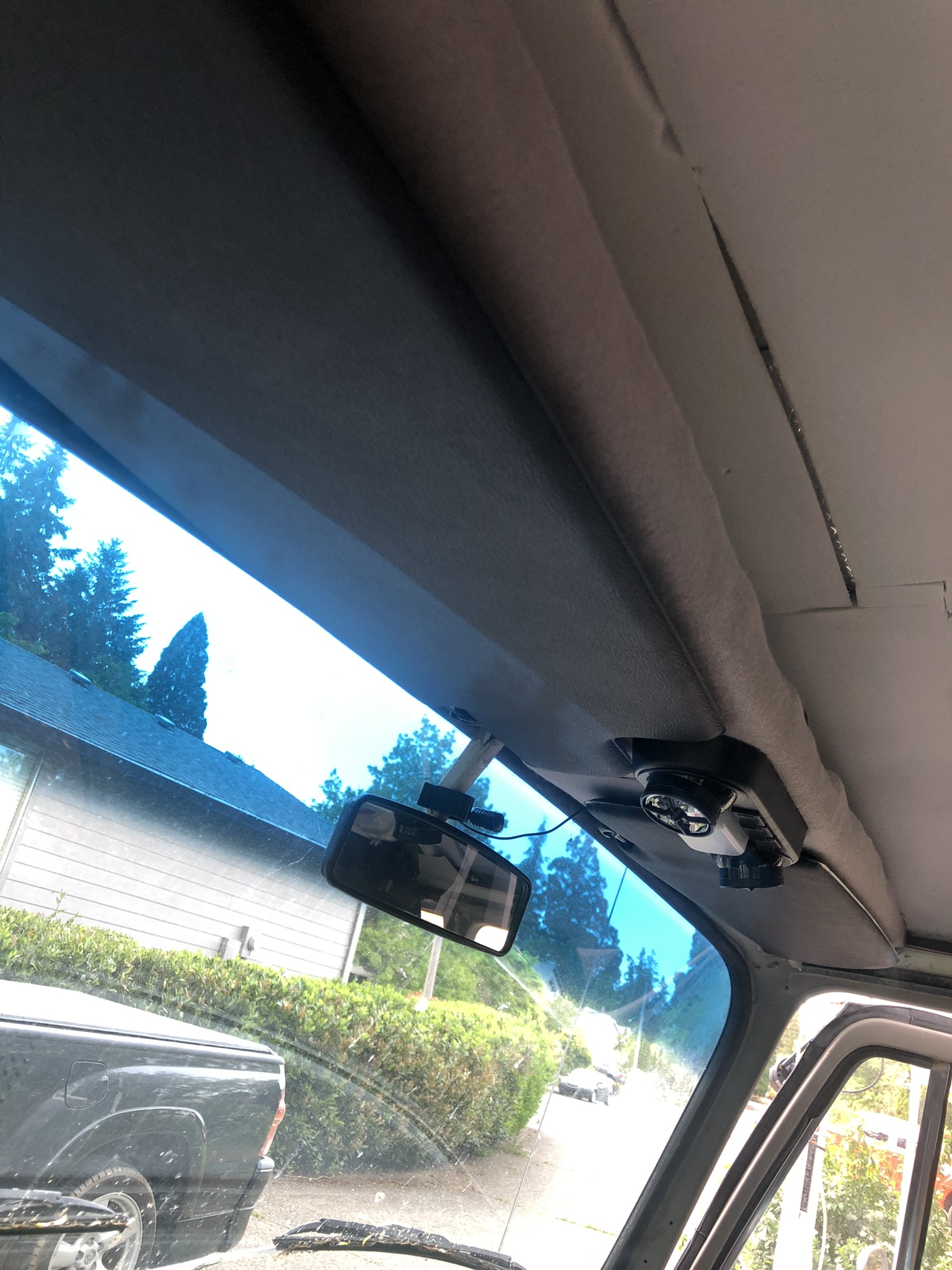
On to the drive! Hapy started right up like he had been driven the day before. The throttle is super responsive, and the engine drove like a champ. He still doesn't like 2nd gear, but I haven't done anything to address that (it might be my install of the Scat short-throw shifter). The overall low-end drone is MUCH quieter, but some rattles remain, especially the screens in the jealous windows. I probably have them installed incorrectly (this video shows correct). Hapy still stops well, and he takes corners WAY better. There was almost no sway around street corners; of course, we did not drive very far nor very fast. We simply drove to a nearby park, played with the dog and returned home by way of the local c-store for some ice cream on a stick. The combo oil pressure / temp gauge still works great, and we did not throw any codes. While we didn't get above 35mph, the sound inside the bus never grew so loud that we couldn't talk at a conversational level. We could not hear the hum of the tires at all, and we really did not notice the sound of the engine. We could hear it, sure, but it was not as ever-present as it used to be. Recall, I used to describe the noise while driving the bus like sitting in an old metal shed next to a running a diesel generator, in a wind-storm. It is definitely not like that around town. I will execute a full decibel test lap to test the noise at highway speeds, but first, there are some things to fix.

The Issues
First, the exterior lights continue to produce phantoms. The brake pedal causes a bunch of the exterior lights (like the front running lights?) to light up, but not both brake lights. Also, the turn signal doesn't work when the brake pedal is pressed. No pedal and no running lights on... and the blinkers work. I remembered that I had the exact same experience when I took Hapy on that decibel test drive (buried in the Hapy Noises - Part 2 post). So, nothing I did over the winter caused it, but nothing fixed it either.

Probably equally important, the fan switch no longer triggered the fans to fire up. After we returned home, I found that one of my wiring bits had become disconnected. While repairing, I noticed how hot the wires would get during testing, and decided that I had gone too thin a gauge in some areas. So, I replaced the merged fan ground wires with individual 14ga grounds, and improved the supply-side to 14ga as well. The fans now both work, and the wires are air temperature.

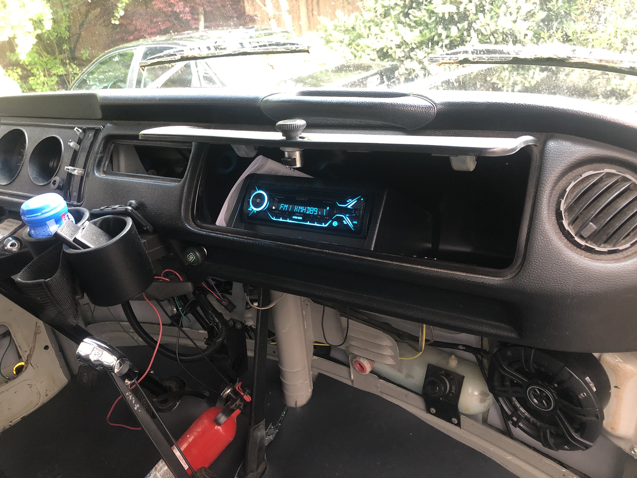
The speedometer didn't work. I must have disconnected the speedo to get into the dash at some point over the winter that I don't remember and failed to reconnect it. This took no brainpower, just lots of patience opening up the dashboard, and trying not to upset any of the wiring back there.

We dropped into that awful 1200RPM limp mode right before we shoved off, but it only happened that one time. Believing I had fixed that before, this was especially frustrating. I must have bumped the wiring connection at the pedal while installing the jute and MLV. I checked those connections (pressing the joint-points firmly between my fingers), but nothing felt off. After multiple drives since, Hapy has not dropped into that 1200RPM limp mode again. 

Last, Hapy had not yet received his annual Spring cleaning (after-photo is at the top). So, he had a blanket of pollen on his pop top, moss on his window seals / windshield wipers, dull looking paint and dirty windows. The spring wash is the biggest of the year, taking a couple of hours, but it is so worth it.

Exterior Lighting Diagnosing
I have tried so many times to figure this out, and so many ways, but I had not been successful. I won't list them, but between resistance and voltage testing everywhere, running test wires the length of the bus, and replacing things, I thought I had tried everything. This weird brake light thing had been a recurring phantom for years, practically since I first did the engine swap. One of the frequent causes for the issue to return after being gone for a while was a remove/install of the battery. This always seemed strange. Sure, the battery is part of the electrical system, but why would it re-conjure an electrical ghost? It occurred to me this time around that the old 20-pin diagnosis plug is back by the battery. Perhaps my incomplete removal of that plug and related wires is a contributing factor?

Unable to determine this through my prior methods, I did something completely different. I removed the tail light assemblies from the bus, letting them loosely hang in the body holes. I took a different 12V auto battery, and ran a test wire from its ground post to the body ground point next to the main on-board battery. Using a fused wire, I touched various light circuits to see which ones worked as expected and which did not. All of this time, I had believed the issue was in the passenger tail-light: it is the light fixture closest to the battery, so I thought I was bumping something while installing the battery. Nope. The tail-light circuits would fire the correct lights. When I ran the same test on the passenger light fixture, lights were batty like I described above.

I checked the wiring diagram related to the driver tail light, and noticed that there was a tie-in between it and the battery location: the old test plug circuit. The yellow circled 9, 10 and 12 which tie into the driver tail light all correspond to the pin numbers in the plug. I knew that the running light was the one that was lighting up in-error, so I figured that red wire was the compromised one. I cut it off at the tail light, and the phantom behavior ended. Both brake lights illuminate when I step on the brake pedal, and all the running lights light up correctly (and only when I turn on the lights, not when I step on the brake).
 
I ultimately cut off all of the wires going into that old diagnosis plug at the plug, and cut the diagnosis wire from the passenger-side rear turn signal. I will probably have to go back into the driver side and cut off the remaining diagnosis wires to make sure I have really exorcised the electrical demons.

Victory Lap
With the brake lights working, the speedo showing speed, the fans firing and the body looking clean, Hapy and I were ready for a test. I figured that I had numbers for the test lap around the neighborhood from last Fall (documented here), so combining a test lap with a decibel collection made sense. Other than all of the changes I made for sound containment, there were no only other variables. Well... I took one lap, but it started just pouring rain, so I took another one. After that one, I realized that I did not know which "filter" to use on the reader because I didn't document that. I know I made a choice last time, though. Still, I think the test was valid enough for my not-terribly-scientific method. This time, I just used the default "A" filter. I did one last lap, but discovered at the end that I had failed to start the dB recording. Sigh...

Fall 2021 (pre-sound absorb) test:
Sitting at idle (900 RPM): 60dB
Around town (less than 40mph): 65dB +/- 5dB. 75dB peak
On the byways (above 40 but under 55): 65dB +/- 10dB

Spring 2022 (post-sound absorb) test:
Sitting at idle (900 RPM): between 55db and 60dB
Around town (less than 40mph):  60dB - 65dB. 70dB peak during highest-rev
On the byways (above 40 but under 55): 65dB - 70dB

Looking at those numbers, I am not impressed, nor do I expect you to be. That was a LOT of work for not much gain. I hit my original goal of dropping the overall sound and the peaks by 5dB, but after the initial drive-about experience, I was expecting more. Again, I need to remind myself that 5dB is actually a large span. Consider, 60dB is normal conversation and 70dB is a running vacuum cleaner. That is a huge difference for an increment of 10. Also, consider that in the link I used for sound level references, it includes "passenger car" at 70dB. So, if my drive around the smaller test loop only peaked (and even then only twice) at 70dB, then Hapy is quieter than a typical passenger car inside. Okay, maybe I'm feeling a little better about it. One last thing to consider.... if I used a different filter last time, then the numbers collected last time should have been much higher, or my efforts were a complete waste of time and money. Since the perceived noise is so much better, I am inclined to believe that I used filter A last time too, since that is the default. Here's an interesting link about filters.
 
At this point, Hapy is ready for summer, and it really could not have happened any later. While I intend to circle back on parts of this project, I do not expect to have to take Hapy off the road to do so. Yes, the furnace needs a re-do, the fridge cabinet is still in pieces, neither the headliner nor the carpet is in... he is still ready for camping. So, for the next few months, we are going to enjoy that, and I will be returning my attention to Zed. Last Summer ended with Zed still in primer. I would like to end this Summer with him painted, and ready for interior work over the Fall/Winter/Spring.

Well, that's it for today. Thanks, as always, for following along-

Tuesday, June 21, 2022

Interior Carded

Once the headbanger was installed, getting the interior to a usable state was a downhill run. This post is really more a collection of all the little things that got done so we could hit the road. So, for today, "complete" means "good enough for this Summer"; it does not mean we're done. I will be picking this up once camping season comes to an end in October. Before I begin, Hapy Summer Solstice.

Cab Floor Complete
I had left some of the MLV splits un-taped. So, I started with that. I discovered that the Jute and MLV was too wide between the outer edges of the seat rails and the doors to allow them to close easily, so I trimmed them down. Then, the edges were taped down.

Sun Visors
sun visors in
One of the upsides to the new shelf was the potential addition of sun-visors. The visors that are on the market these days are not the same as the ones I removed; that could be a reflection of my old visors, however. These new ones are shaped differently, with a pop-out on the end that is designed to go behind / around the mirror, and the little stick on the end that is supposed to go into the little keeper near the mirror is therefore much shorter. So, if I was looking for a direct-replacement, these would NOT have fit properly, but, again, it is entirely possible that the PO installed bug visors or something way back when. The mounting base near the A-pillar is the same. I re-tapped the holes, knowing at least one, if not all of them, had metal screws instead of bolts at one time before. I threaded M4 Phillips bolts in to hold the visors. I attached the little keeper thing to the underside of the shelf. So, the visor, when not in use, tucks flat to the underside of the shelf. It turned out that the weird shape of the visor allowed it to almost wrap around the light fixture, looking like it was designed for that install. Sometimes, its just better to be lucky than good.

Cab Door Cards
cab cards nearly complete
Recall, my old door cards were falling apart cardboard. There's a cat in Arizona named Werksberg who makes door cards out of PVC, and I ordered a set last Fall (his TheSamba ad). Apparently, his costs are skyrocketing so if you want some of these and have been sitting on the fence, you might get priced out if you don't make a decision soon. Anyway, I was finally ready to install the fronts. Unlike the original cards which need to be installed with metal clips into little rubber boots, these cards deliver with small plastic molly's which press through the card into the original holes. They appear re-usable. We'll see. The driver door card is not staying put, even after adding double-sided tape so I may need to add screws.

When I removed the original-to-me cards, I removed the little door vent things. I set them in my trove of parts and did not install them when I put on the cardboard cards. I put them on this time. The door looks much more finished now, as you can see in the picture above-right, here. The rest of the card install is the same as original. The window crank removes / installs with a Phillips screwdriver. As does the chrome door latch mechanism and the door pull strap. Once installed, the door looks so much better than it did. I have not decided if I will apply the thin closed cell foam or not, but I am not doing it for now.

Kicks
partitions and mid-walls carded
The last thing I got after in the cab was the re-install of the kick panels. With the new flooring and 4-1/2" speakers, this was not as simple as before. Still, I found by setting the outer edge and then bending the card, I could get it pretty much where I wanted it. I pulled the jute and MLV up, allowing the card to sit on the floor. I could remove them, and cut off the lower 1/2" so they sit on top instead. Meh. Something to think about as we drive around this summer.

Slider Door
Moving rearward, I pulled the middle row seat out and the original-to-me slider door card. The slider had not gotten much treatment over the years, so it got CLD and 2 layers of Mega Zorbe. I thought the extra layer might reduce the racket when the door opens. It didn't at first. I spent some time with oil & grease cleaner working on the door runners, and that actually helped a little bit. The lower door roller is the source of the lion's share of the noise and noticed that the outer edge of the runner was a simple 1/4" tall thin bit of steel. So, I ran some leftover white "U" seal I had from doing the luggage rack to see if that would help. Nope. It effectively pressed the wheel against the inner steel track edge, causing it to make a different, but equally unpleasant, noise. I concluded the wheel was the noise-creator, and I ordered a replacement lower guide with a vinyl wheel, instead of steel.
rear tail gate carded

There are 2 bolts and one Allen-screw holding the guide to the door. The bolts on the old guide were so rusted, they broke off, leaving me with just an Allen-bolt holding the guide in place. I will periodically shoot those rusted bolts with penetrant, and when I am able to remove them, I will use M6 bolts in their place. I will apply anti-seize, though. With the new lower guide in, the door was quieter, and operated more smoothly, but the upper guide was making noticeable noise now. So, I removed it, and improved it with penetrating oil until the guide-wheel would easily spin between my fingers. I re-installed it, and now the door was as quiet as a modern slider.

More Cards
I had some daylight remaining, so I grabbed the door card for the slider, and installed it. I also installed the card for the wall opposite the slider, and installed it. I did the rear tail gate and the extra cards for the rear-facing partitions behind the front seats. Each of these took some fiddling to get right, but that was on account of Hapy, not because of the cards. These things are great; the holes are mostly in the exactly right spots and the bag of Mollys had more than enough fasteners for me to damage a bunch of them and still not run out. I believe I can fit more sound deadener between the partition cards and the partition, and I may need some foam to reduce vibration noise, but right now, the interior of the bus looks really good. Removing those cards to add noise deadener will be simple when /if  I choose to do it.

I have a couple of cards remaining to be installed along the seat pedestals and I'll do them as the mood strikes / time permits. For those keeping track at home, I have installed the panels which sit at either end of the rock-n-roll bed, arching over the rear wheel wells, and have I attached the panels that cover the bare steel in the sleeping area. Because the sleeping area cards abut the rear-wheel cards, I needed to do them in the right order. As you can see in the image on the right, here, these cards, when used together, make a nearly seamless span. Boo and I will especially appreciate the sleeping area cards when we're camping. There are few things as jar-awake as having some bare skin touch up against the metal side after it has cooled down overnight. That is some quick-awakening. While this plastic / PVC will not be a great deal better, it does create a foundation for some foam and then some fabric later.

At this point, I felt ready for a test flight. I'll post on that next time. Thanks, as always, for following along-

Tuesday, June 14, 2022

Enter the Headbanger (Part 3)

I thought I had gotten as far on the headbanger as I intended to for this camping season.... but, today, I wrap this puppy up. Pretty much. I designed, assembled and wired it in Part 1. In Part 2, I figured out how to mount it into the bus, filled in all the gaps with cardboard and applied trunk carpet everywhere a headliner would not be. And, of course, there was more wiring. Today, we complete the headbanger enough for use while we consider how and if it could be improved.

Before I begin, for my US readers, Hapy Flag Day. Earlier this year, I mentioned Phil and Phrends touring through the PacNW. We did that run, and I'll post on that adventure here shortly. But first, the completion-ish of the headbanger.

Headlining the Headbanger
The next logical step was applying headliner to the parts of the headbanger that were still exposed cardboard and OSB. I had a section of material that had been cut off the start of the roll that was about 2 feet deep (56" wide). I needed 19 inches. With the extra material, I was able to get the lines in the headliner to align with the bottom straight edge of the headbanger. I set the cabinet upside down on the tool cabinet with the rear edge facing me. I flopped the material over the speaker boxes and set the lines parallel with the rear edge. I rolled the material back on itself and applied contact cement to the OSB (2 coats) and then a light brushing on the headliner backside. I set the edge and flattened it with my hands. Once set, I rotated the cabinet 180* so the just-cemented part was facing away from me. I worked my way towards me, applying generous amounts of contact cement from side to side in about 6" wide swathes. I double-coated the cabinet, while single-coating the headliner. At each step, I smoothed the headliner down so there were minimal wrinkles and pulls.

With the main section covered, I considered the sides. I had enough material so I didn't need to cut completely separate pieces, but I would need a seam. I decided to make a long seam along the angled section rather than a short seam along the flat bottom at the rear. I did this for 2 reasons. First, the lines of the headliner run straight up-and-down like this, and they would have been running at an odd angle had I just folded along that edge. Second, I was having a hard time visualizing where to make the cut along that shorter edge. I made the fold, applied the headliner with contact cement and then cut off the extra floppy bit. In the end, I am not thrilled with the seam and will look for ideas for how to cover it with something visually inobtrusive. From a distance, it looks fine, I suppose.

All wrapped with headliner, I needed to remove the section in the middle. This cut was not my finest work, and after the less than perfect seams along the outer edge, these cuts further confirmed the need for something to clean-up the transition from trunk carpet to headliner. a small plastic 90* strip might work. Anyway, last, I cut the holes for the speakers and then poked holes through the headliner from inside the speaker boxes for the speaker mounting screws.

Install
I had hoped to have the headliner on the rear ceiling before installing the headbanger, but it's not in and I want to get Hapy on the road. So, I jumped to the install, and ultimately, this was a good thing. My method for raising the cabinet for install is unorthodox, but it worked. I set a plastic recycling tub onto the rear bed cushion. Onto that, I stacked the top and bottom cushions for the rock-n-roll bed. This wobbly stack sets the cabinet in the perfect spot to send through the rear bolts. These are all M4 bolts with lock washers and plain washers. These line up perfectly. Added to the left-center bolt are the grounding ring terminals for the USB chargers. I sent the bolts through enough to loosely hold the rear of the cabinet in place. While I could still reach them, I plugged in the speaker and the USB wires. Then I moved around to the front.

Up front, I discovered that the outer mounts were not going to work. The passenger side mount had the riv-nut in the wrong place (just barely, but wrong). The driver side mount riv-nut did not set, falling out as I tried to thread into it. I discovered that the location was too roundy for a riv-nut to really grab on after trying to set another riv-nut and failing. I know, I posted that I checked the alignment in part 2. I did, but checking the alignment and actually installing are 2 different things, and they are apparently different enough to matter. Lesson learned. So, the front is now held in place with 2 M4 bolts instead of 4. These were sent up the center, around the leading edge "gap filler". Now that it is all together and in place, that center gap fill probably could have been eliminated. As it is, it is very close to the rear light fixture. I may remove it in a later version, but it really does finish off that top edge, and it does pull the 2 speaker box sides together. As to the front edge mounts, I may send through a couple self-tapping sheet metal screws to help hold the cabinet up. It pains me to think that way, though, and as of right now, the cabinet it holding firm to the ceiling.

Once I had the front bolts torqued down, I torqued down the rear ones, and made sure the cables were tucked up out of the way. Satisfied, I pulled the rock-n-roll bed cushions and the recycling tub down. You can see the cushions through the rear window in the picture below.

Speaker Install
Installing speakers is not exactly new ground to cover. The only thing that made this interesting was that I was doing it upside down. Quick side-bar, though... I was able to get in and out the rear tail gate much easier than I expected to. In fact, it is easier to get in/out that way now, than it was 10+ years ago when the original 1972 Westfalia shelf was in there. Figure that I am not getting more nimble; this much smaller unit, and, with the angled front (front is front), it is not nearly as intrusive as the old shelf. I was able to sit upright on the bed (no rock-n-roll parts yet). I would wager that if I sat up suddenly in the middle of the night from a dead sleep, I would not slam my head against the underside of this cabinet. More and more winning.

Anyway, about the speaker install: One speaker at a time, I stuffed poly-fill into the speaker boxes... well, I stuffed poly-fill into the sides and corners of the speaker-boxes. Putting it anywhere else, it would have just fallen out. Then, I wired up the speaker and held it in place (with the cover) and screwed it into the headbanger. Repeat for the second side. Once wired up, I flipped the switch to turn them on and shazam, we have more sound blowing. Anxious to try it out, I closed all the doors, hopped into the driver seat and cranked up whatever was playing on the hard rock station at the time (Cowboy by Kid Rock). Wow. So much sound. After Kid Rock finished, Pink Floyd's "Dark Side of the Moon" started, giving me a sense of the system's fuller dynamics. This is gonna be fun.

Well, that's it for now. I will probably revisit the headbanger when I lower it to put the headliner on the rear ceiling. We are going to drive around like this for a while, though, to see whether we really need or want to change anything. Right now, it seems pretty great.

Thanks, as always, for following along-

Tuesday, June 7, 2022

Returning to Hapy Sounds - Part 3

I think I've touched pretty much every other part of Hapy's sound system this winter/spring, so I guess it's only right to finish it up with improving the head unit install. Of course, no stereo entry is complete without some fun with wiring, so there's some of that too. I am still pushing hard to have the bus ready for camping season. So, while this may seem to be a departure from the shortest trip to complete, we can't go camping or long-distance driving without sounds. In a way, the ability to easily hear the stereo was what triggered the noise containment project. We just gotta have it.

How Did We Get Here?
planning the cut
While I was working on getting sound deadener behind the original cardboard glove box, I decided to remove it for better access. I had already disconnected the luxury electrical set up for the electrical rough-in (See Ceiling Wire Rough In), so I simply unplugged the head unit that I had stashed in the glove box and pushed the plug out the hole I had bored in it. After emptying the remaining contents into a small cardboard box, I looked at the glove box. I discovered that the old cardboard box was holding on for dear life, and the removal of the support bar (Phillips screw on the underside of the glove box) did it in. The rear edge (front is front) that is pressed up against the dash had been all raggedy anyway, and once I started removing the box, that edge powdered off in chunks. So, I ordered one of those ABS plastic replacements. With the deteriorating original box in hand, I considered how I could more permanently mount the stereo when the new ABS box arrived. These were on back-order, like so many things these days, so I had to wait a while to complete this.

Solve the Head
mock-up with original box
I got a Metra Universal under-dash mounting kit (model 99-9000), and started fiddling with how that rectangular kit could fit into the rounded glove box. After several measure and test-fit attempts, it was fairly clear that hanging the stereo from the top of the box was not practical. The glove box was too shallow and the mounting kit too deep. I would have had to cut a large rectangle out of the rear of the glove box, and I'm not sure it would have fit right afterwards.

Back when I first got this head unit, I set the head unit in the glove box, on top of the molded shipping cardboard. It fit, and I could manage all of the buttons. Since hanging the box from above didn't work, I tried the kit upside down, mounting to the floor of the glove box. The kit was still too deep, but only by an inch or so. I measured, marked and cut an angle off the rear and it snugged right in. I confirmed that the stereo unit did not extend past the shortest point in the trimmed-down mount-box-thing. To mount the cut-down box to the glove box, things got interesting. I have demonstrated multiple times that I cannot manage to transfer measurements consistently. So, rather than swiss-cheese the underside of the box, I set the kit where I wanted it and marked two holes on the inside (blue tape, then a marker) of the box. I drilled out those 2 holes so I could align the rest of the box from below. I set the box such that the holes aligned and then held it in place with vice-grips while I marked the rest of the holes. Then, I drilled them out. Even then, the holes were not 100% perfect, so I expanded them where needed with a file. I added a hole at the rear of the glove box for the wiring pigtail with a hole saw and then attached the mounting kit with M3 bolts. That sentence took seconds to write, but the work took a couple of hours: tiny bolts + little finger room = patience needed.

Because, Wiring
marking holes
When I did the head unit the first time, I simply ran the power wire on the floor under the carpet. That was very Agile, demonstrated that having a stereo was a good thing, and that leveraging the luxury battery was a great call. So, since the stereo and the rest of the wiring in the bus was torn apart anyway, I changed the wire routing. Similar to the T12 front-to-back cable, I ran 2 sets of speaker cables and a power cable from behind the dash, down through the cable port behind the accelerator pedal and under the bus. I ran this collection of wiring along the frame and then found an existing factory hole (probably a drain hole) just inside of the passenger rear suspension up into the rock-n-roll bed. To keep things straight, the speaker wires were marked with tape (yellow-left, orange-right).

The yellow power wire was routed over to the driver side under the rock-n-roll bed and lightly tucked into place so it doesn't dangle into things and then integrated into the new fuse box (See Luxury Electrical Restored). Onto the speaker wires, I re-integrated the female wire connectors that I had before. One pair of two is under the rock-n-roll bed on the passenger side. Similar to the power wire, I tucked the wires under the rear edge of the bed floor so they stay out of the way. The other pair (recall there were 2 before) was sent through to the other side of the rock-n-roll bed up into rear of the formerly-fridge cabinet. Later, I may switch the female wire connectors to ports, but not today. At this point, I grabbed the floating remote rear speakers and plugged them in.

Back at the front of the bus, I integrated the various rear-speaker wires. Consider there's the pair that run up the A-pillar and to the rear over the sleeping area and the pair that now run under the bus to the rock-n-roll bed. The pair that run under the bus were the same as the pair that used to run along the floor. When I cut them, I marked them left-right. The pair that were sent up the A-pillar, however, were not. to figure out which one was which, I stripped one pair and clipped them together. Then, at the plug at the rear of the bus, I checked the plugs for continuity between the center-hole and the outer ring. One was infinite, the other was almost 0 resistance. 0 resistance is the winner, so I marked the end at the front with the same color tape (orange:right, IIRC) and then marked the other one. I spliced the remote speaker wire pairs together first, and then added the tiny wire from the stereo loom. I expect I will be adding an amp at some point, so I did not soldier them up. 

Putting it Together
note the mounting bolts
With the speaker wires integrated into the loom, the hard part was done. I spliced in ground and the yellow power wire and cleaned up the loom -to- front speaker connection. We were ready for install. The plastic glove box does not fit as easily into the dash as the old cardboard one does. I think it is a little larger, which really is fine. I needed and found a longer mounting screw (about an inch longer) for the support bar. To set the box in place, I found that suspending it in the support strap with the opening pointing up was most effective. Then, the box just tips into place. Since the box is bigger and less malleable, I focused on getting the bottom edge in the right spot, and let the top edge sit high. I sent the mounting screw home and the box doesn't wiggle at all.

I sent the wiring loom, the antenna cable and the wireless phone mic cord through the hole in the back of the glove box and plugged everything in. I took a quick glance at the fuse box and saw the tell-tale red LED telling me that I had a good circuit. Loving that fuse box feature. I set the stereo into the hole added a 10A fuse and fired up the local jazz station. After a few set-up steps on the stereo and burying the excess wire, the stereo is as complete as it needs to be for this Summer. 

So, the stereo is complete.... until I get a wild hair again to change it again. Like, wouldn't it be cool to have remote speaker plugs outside the slider so we can close the door without interrupting the music when set up for festivals or camping? Moments like this are when it is so obvious that this bus will never be done. There are always new ideas.

That's it for today. Thanks, as always, for following along-