Showing posts with label control. Show all posts

Tuesday, July 16, 2024

Door Cards

Today I will be picking up where I left off regarding the doors. As I described in my last post, the front doors now open, close and lock like a real car. No slamming, not funny jiggling of the handle, etc. Just open, close and lock. Well, the passenger door lock is different from the driver, but I'll swap that out once I find all my parts. Anyway, since I had to remove the cards to fix the doors, I thought I would take the opportunity to improve them.

Door Cards As-Was
foamed card installed
With operational doors, I got to thinking about how to get the door cards to hold to their respective doors. The Arizona gentleman who ran the business creating and selling these ABS door cards was looking to sell off the business a couple of years ago, so I imagine that has happened by now. He had a mixture of molly-based fasteners delivered with the cards. Either the fastener was a screw that dug into the molly which was pushed through the card into the original mounting hole or it was a push-to-hold plastic bit. Regardless, the molly's did not hold in all of the original mounting holes on my bus (YMMV). This could have been poor implementation on my part, something particular about Hapy or just less-than-ideal engineering on the fasteners. It doesn't really matter; for Hapy, they did not work. When combined with the slamming doors, the door cards would rattle and Hapy had a very junky vibe. Now that the doors no longer need to slam shut, improving the cards adherence to the doors will help un-jalopy Hapy that little bit more.

Door Cards, Mounting Upgrade
broken M4 riv-nut bit
To remedy the floppy door cards, I tried a more permanent solution: Riv-nuts and bolts. The plan: into each original mounting hole in the door, I attach a riv-nut (it's a nut that is applied with a rivet gun, basically), and then send a bolt through a washer and then the card, into the riv-nut. Such a simple plan, and while a little time-consuming, it was easy to do. Of course, I found that not all of the original holes were the same size. To fix, I used some as large as an M6 or as small as an M4. I think this is why the supplied molly-based fasteners did not work as well: the M6-sized holes were simply too big for the molly and they fell out. As shown in the picture here, too much pressure with the riveting tool and you can break it. Once I had all of the riv-nuts set, I shifted to the cards themselves.

Noise Abatement Revisit
setting riv-nut
While I had the door cards out of the bus for repairs, I applied a thin noise-absorbing closed-cell foam to the 3 cards. This material was among the things I got a few years ago when I did the sound deadening effort, and it's application to the door cards was part of that plan. At the time, the research I did (See Hapy Noises - Part 2) indicated that multiple attack vectors would bring the best result: Constrained Layered Dampener, an open cell sound deadener like Jute Thermal and then Mass Loaded Vinyl. These all really address reducing the impact of external (and mechanical) noises transferring into the cabin. Any noises or sound that make it into the cabin which are not absorbed by the seats are prone to bouncing around. I placed some larger acoustic panels (these) under the upper bunk, in the slot where the original sunroof used to go. I believe they are helping absorb some ambient sound. I also covered the ceiling with Mega Zorbe to address the sound reflection and ambient sound absorption. In the picture on the right, here, you can see the MegaZorbe applied to the inside of the outer door skin. 

Based on the tests I did at the end of the effort, the only real gains as-measured were in the "around town" (under 40mph) zone. Decibels at idle or on the highway appeared about the same. In practice, however, using a less complex "measure" like how loud we have to run the stereo to hear it on the highway, it is definitely quieter. An even less precise indicator is how loud we need to speak to each other to have a conversation: barely louder than we talk at home, which is quiet (no yelling house) where we used to have to almost yell without the stereo on. So, I am setting aside the scientific evidence and embracing the anecdotal: this implementation of the sound abatement absolutely and significantly improved our road tripping experience. I may take more readings because the numbers I took before continue to bother me.

Door Cards, Reflective Sound Absorption Added
applying the foam
So, with all that context, I decided to press forward on my original plan to apply the thin foam sheets to the hard plastic cards. I started with the cards along the sleeping deck, running from the rear hatch forward along both sides under the windows to the rear of the rock-n-roll bed (1 foot tall by about 4 feet long). I started here for 2 reasons: it was very easy and the plastic cards were jarring-cold when bare skin pressed against them while sleeping. The foam definitely improved that.

For the slider and front doors, I simply traced the door shape on the peel-off paper side of the peel-n-stick foam and cut along the line with scissors. I aligned the cut along the card and peel-stuck them down, working from one corner, down along one side and then across. I will be applying carpet later, but felt that the foam might help reduce the reflected sound while also providing a cushion under the carpet.

With the foam applied to the cards, I considered the game of "which bolt fits" for each mounting point. I could have just started trying bolts, but that felt like an exercise in frustration. So, instead, I grabbed some painters tape and marked to the outside of each hole (where the card would not cover) which bolt size to use. I set the front door cards in place using the door pull to hold the card in the right spot. Then, I simply sent bolts through a black vinyl washer and then the card into the door. Once mounted, I removed the tape. Easy-peasy. If you do this, I suggest that you do the corners first, and only threaded enough to hold. Then, skip around the card, and have all of them like that before you start tightening. Then, again, start with the corners and pay close attention to the bottom edge near the vent. These ABS cards fit perfectly, but the one hole near the bottom align the trailing edge of the door did not line up for me and I had to skip it. YMMV, of course.

slider door foamed
The door card kit included panels for the wall under the driver-side jealous window and for the partitions behind the front seats. I have yet to do those cards, but I am holding off on doing those until I am ready to fast-follow with carpet. The foam is not as scratch-resilient as the hard plastic, and those cards take the brunt of the abuse when camping or music gear is loaded, unloaded and in-motion. So, I will apply the foam and the carpet at the same time. All of that will happen at some point in the future. As it is right now, there is that little bit less noise reflection happening and when bare skin touches the side of the sleeping area, it no longer triggers a shuddering wake up. We are taking the win.

---

That's it for today. Thanks, as always, for following along-

Tuesday, April 2, 2024

Mini Q-Tron modifications

In a complete departure from my usual posts about cars, my bus, or even working on an old house, today's post is about my electrical experiments on an Electro-Harmonix Mini Q-Tron. It took me quite a bit of time to find bits and pieces of advice on how to meaningfully modify these things, so this may help others who endeavor to do the same. I do need to point out that my experiments and eventual (partial) success was only possible because of folks on various forums making small modifications and improvements.

What / Why Mini Q-Tron
So, what is a Mini Q-Tron and why would anyone want it and then want to modify it? It is a "T-Wah" or touch-wah pedal (also called an envelope filter) that adds a fixed amount of "wah" or flange to the signal passed into it versus a classic wah pedal that changes the tone based on how the user moves the "accelerator" pedal. There are 3 knobs that control the intensity, shape and tone of the change. Why would you want it? On a bass, it has very limited application, but it's fun. I imagine a Q-Tron is much more useful for a guitarist, especially if you are seeking that early-80's Jerry Garcia tone before he started experimenting with Midi. Anyway, if it's so fun, why modify it?

There is 1 big reason why the Mini Q-Tron goes from "hey this is cool" to sits-on-a-shelf-never-used or simply returned/sold: the volume output of the unit is louder when turned on than when by-passed. So, if you're playing something and want to add a little T-Wah to it, you click it on and suddenly you are much louder. So, turning it on and off during a song is not possible without a volume pedal next to it or some other pedal configuration. I have tried placing a compressor after it, and that helps, but if you like to have some uncompressed signal pass thru your compressor (and your compressor supports that like mine does), the volume spike will still be experienced after the compressor. To address the volume change between by-pass and in-use, we add a volume knob. That solves the 1 big reason.

In my opinion, there is a second short-coming with the Mini Q-Tron: it lacks a blend control. A blend control is another knob allows some degree of original (called "dry") signal to pass through even when the pedal is in use. This adds another whole dimension to the T-Wah effect. You can set intensity and shape that you want and then vary how much influence that changed sound has on your final output. A blend control often appears on bass-centric pedals so some unmodified signal can pass through.

Last, for me, this pedal was a gift. I can't return it and guilt would prevent me from selling it. I got it almost 20 years ago and it has sat on a shelf most of that time. I figure if I damage or destroy it, I haven't lost anything other than time. I suppose purposely destroying a gift could be worse than selling it, but let's not get all caught up in ethics here. Besides, this kind of electrical work is fun: clean, relatively modern wiring managed while indoors (versus 50 years old in the rain).

Output Volume Knob
There is a great thread on the TalkBass forum that goes into some detail similar to what I described above. More importantly, there are 2 pictures which show exactly where to make modifications to include a volume knob. Out of respect for the author and the forum, I won't repost the text nor images, but you basically add a potentiometer between the circuit board and the switch, in the signal path of the blue wire. What was not clearly defined was the size of the resistor. The forum-goers seemed to circle around a 10k pot, and I found that to be almost as useless as no knob at all. The knob had very little room for adjustment between no signal and full signal. There are limits to my purchasing and experimenting, but even the 2k pot I am using now has a limited amount of sweep on it. I have it less than a 2/3 turn off the bottom (see picture on the right here) since it is effectively full signal above that. The 10k pot had significantly less room before full signal passed; it was like a nudge off the bottom. I might try a 500ohm pot if I grow tired of small bumps to the knob changing the output dramatically. As it is, the volume is mostly set-and-forget since the whole point is having the volume not spike simply from the pedal being engaged. I say mostly because depending on what is upstream, you may actually have to change the volume. I discovered that during a jam this past weekend.

Other than the resistor value, I followed the instructions fairly closely and tested the output by sending signal into my compressor and adjusting the knob based on the compressor input LED's values until they remained the same when turning the Q-Tron on and off. At this point, I felt had the Q-Tron fairly well-tamed. I even drilled the hole on the face of the case, passed the stalk up thru, nutted it down and stuck a knob on there. That's my mini Q-Tron in the picture on the right at this point.

Blend Control
I have tried the Q-Tron like that for a little bit and I like the wah effect, but not all the time and sometimes it got to the point of being intrusive. At least now, I can add it mid-song and not throw the bass way out in front of everything else. There are some songs, like maybe some old 70's tunes or artists (like the Meters, Parliament or even Bill Withers, for example) that lend themselves well to a little wah on the bass. Even if the volume is consistent, the effect doesn't sit in the mix EQ right: the low end is completely sacrificed; this is exactly why bass effect pedals often have a blend knob. You can't have fat 70's funk and no low end. That just ain't happenin. To remedy, I want to add some original signal back in. I could split the signal before it enters the Q-Tron and have another pedal control the signal flow, but floorspace on small stages is already at a premium and the fewer things I need to plug together, the fewer things that could go wrong. So, I started looking into adding a blend control to the pedal. Regardless of how well my GoogleFu was working any given day, I was unable to find a simple pictorial or text-only how-to anywhere. So, I went experimenting without a net, and while it was interesting, they were ultimately fruitless. Hopefully these efforts help someone else, but at minimum, I now understand that blending something that could form a circuit loop requires more than a simple stacked knob.... which is why I could not find something simple. There isn't one.

Blend Attempt Learnings
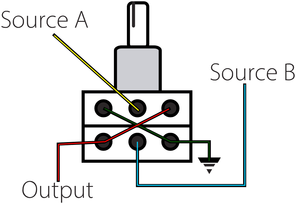
I tried anyway, and documented my experiments here so you don't waste your time. A blend control potentiometer is unlike a volume or tone knob. Those other knobs have one variable resistor, generally accepting signal from the center post and directing it to one post or the other based on the position of the control stalk. They are not all like this so take resistance measurements so you know what you have before you warm up your solder iron. For blending, you cannot simply direct 2 separate inputs into the outer posts to vary what comes out the middle (think like a hot-cold water faucet). It just doesn't work that way. A blend control knob is effectively 2 stacked volume or control knobs managed by a single central stalk. The idea is that when turned one way, the resistance on the upper variable goes one direction while the lower variable goes the opposite direction, depending on which posts you are comparing. In this way, you can control 2 levels to go in opposite or similar directions at the same time.

The blend pots are not always linear and do not all behave like this, though. The NM pot that I started with, for example, has a curve such that at the exact center both sources are at 100%. As the knob moves away from center, one of the stacks drops in volume (raises in resistance) while the other remains constant. In an "AC" knob, the curves are more parabolic, crossing at the middle. So, only at the extreme end is a signal at it's highest or lowest.

To help illustrate the wiring, I nabbed the image up above on the right, here, from a guitar forum post which was describing how to wire up a blend knob between 2 pickups. Similar to the volume knob, the decisions around the resistance value for the blend were not easy. On that forum, it was posed that a lower resistance range would create a smoother transition, so using a NM100k pot would be better than a NM250k pot. It was also made clear that the values of the blend had little to no bearing on the resistance value of an independent volume knob and vice-versa (volume no impact on blend value). Last, I have read varying accounts about grounding or not grounding the blend (black wire path in the drawing). I started with ungrounded cuz easier. It seemed to me that the lower the resistance value, the better the transition, so I got the lowest blend pot I could find: NM25k. I figured if it was too low and it effectively worked like a 3 position switch: all-On | 50-50 | all-Off it would still be better than not having it at all, and then I would explore other, higher resistance settings to find a true blend. Of course, this was all guitarists talking and when I went to some bass forums, it seemed that the lower resistance values would trim some of the bottom end tone. Regardless, I saw that after I'd gotten the NM25k.

I did all the wiring and tested it out, and when the knob was off the center detent, the signal was controlled as I expected it to be: a relative percentage of wet or dry signal relative to the knob position. The issue was when the knob was at or just off center. This is where the "NM" designation above may be important. The curve for an NM pot allows for half of the sweep of the knob to be at full volume while the other half is being reduced. So, at center you have full signal from both sources. Maybe, in the case of building this blend for this application, that was too much signal. Regardless of cause, I got this super-high, almost feedback sound through it when the knob was at center. The picture on the right was taken before I tried out some ground options that seemed to help. Like, I added grounding to the blend knob and the volume knob. The feedback persisted at dead-center. Maybe it was feedback, with a processed signal passing back into the "dry" from where the blend knob was wiring them together at the switch when the knob was at the center of the sweep. I could add a one-way gate to the "dry" signal entering the knob. Or, I could try an "AC" knob that has a very different volume curve that may prevent the feedback loop simply by how the volume levels are controlled.

So, I ordered an AC blend pot and dug into my electrical stuff for the not-gate diode that I used in Hapy's ignition before I re-wired him. I added it to the black-with-white-stripe wire on the left side of the image above, with the side with a stripe (cathode) pointing towards the blend knob. A not-gate diode is basically the same as a back-flow in your plumbing: it prevents the signal from going the wrong way. Signal can go from the anode to the cathode, but not the other way.  I did not give 2 thinks about the size of the diode relative to my project, and the results were enlightening but not right. For Hapy's ignition, the amount of resistance was relatively meaningless since a ton of 12V signal was present. For this, where we are working with miliVolts, this diode introduces considerable resistance to the overall dry signal heading for the blend knob. So much resistance, in fact, that it virtually kills the dry signal, but the feedback stopped. I tried the cathode reversed but that didn't work either. Besides, I had it oriented correctly, it's just the wrong value.

In the end, I removed the diode and returned the unit to the way it was (volume control only). I intend to return when I can find an elegant solution, be it the correct diode or another entire circuit board to add in (maybe something like this). I'm hoping the former, but will do the later if I find I am enjoying the Q-Tron and want to adjust it that little bit more. I took the Q-Tron to a jam on Saturday with a few other pedals I don't get to play with very often, and found that adding a phaser after the Q-Tron took some of the bite out of the t-wah without losing the fun. It felt like some of the lower end came back thru the phaser too, so maybe there's hope for this pedal without a blend control. Time will tell.

Thanks, as always, for following along. I will return to my more typical car/bus/house stuff next time-


Tuesday, February 27, 2024

Hapy Heat Repeat (Part 1)

Ask anyone who has owned or simply driven an old air-cooled Volkswagen in not-Summer and 9 times out of 10 they will regale you with tales of being cold. These awesome vehicles were designed to have heat, its just that they were also designed to be owner-maintained, and maintaining the cabin climate control is not easy. With aftermarket replacements of J-tubes for heater boxes, cardboard pieces eventually failing over time and long channels under the car (where road salt, etc gets in), it's no wonder heat doesn't make it. Anyway, today's post documents another attempt to get some warmth into Hapy, specifically onto my feet and maybe even onto the windscreen.

Why the Obsession
By now, you must wonder why am I so focused on getting heat into the bus. And I get it. Put on a coat or something, right? Besides, it's not like we really get snow in the Northwestern Willamette Valley. This is all true. For folks who own these cars and busses in genuine snow country, I suspect either they are summer-only vehicles or you are far more brave than I, driving in moon boots or something. Around here, we really only have about 10 weeks of warm-to-hot weather out of the 52 in a year. For the rest of the year it is either cold or cold and raining. Driving around in the cold is not as fun when you're bundled up (ski-gear head to toe) and still cold. Regardless, the temperature is hovering around the dew point during those 42 weeks, and overnight for most of the 10 weeks of warm-to-hot season. In the mountains, it approaches the dew point earlier in the evening and remains later into the morning. So, having a means of getting the fog off the windscreen, and not adding to it, is super important.

The Plan
so it begins
Last November, I posted an update (see: Hapy Update) where I replaced Hapy's crappy glow plugs with a new set. I did not circle-back on that since, but he has started without a hitch all winter. Those plugs are fantastic. The real test will be how well they behave next winter. Anyway, in that post, I mentioned that I had acquired a Maradyne Fans heater unit and shut off the Vanagon rear-seat-heat unit because I believed it had started leaking again. We had a "break" in the weather (almost 10*C / 50*F and only occasional rain), so I took the unit out to Hapy. The think was to remove the old, and swap in the new. Ain't nuttin ever that easy, but it's in now.

Old Heat Exit
The Vanagon rear-seat-heat was suspended from beneath the belly of the bus just forward off the radiator. I had fab'd a custom plenum from the heater unit into the original 3" diameter air channel, run coolant lines along the driver side to feed it and run electrical from the dash to control the fan. I hadn't tried to control the valve, choosing to leave it on or off by setting the valve before a drive instead. I unplugged the electrical first, then the flashing/plenum that routed the air into the 3" channel. Then I set to removing the heater from the underside of the bus. Both of the nuts at the bottom of the threaded bolt supporting the unit had rusted so I had to encourage them with a hammer.

Last, the coolant lines needed to be removed. I held the lines closed with vice grips so I did not lose a bunch of coolant and then set a dishpan underneath so I didn't spread coolant all over the ground when I disconnected things. The lines removed easily enough and a small amount of coolant dribbled into the pan. From this I concluded that the unit had been the source of the leak in the cooling system or there would have been more than the few ounces that appeared. I set the unit aside and shifted to the new heater.

New Heater Hung
mounting angle
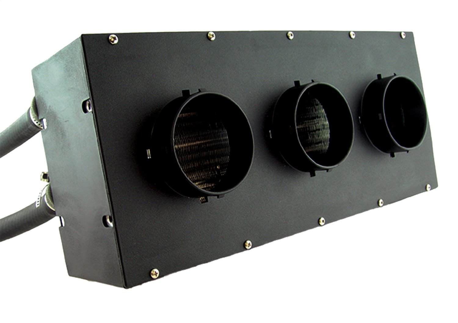
For installing the new unit, I started with placement thinks. I wanted it in essentially the same place, running air into the same 3" diameter hole. The force and size of this new unit dwarfs the Vanagon rear-seat-heat unit, however. The Vanagon unit is 6" tall and about 9" wide. The Maradyne unit is also 6" tall, but it is almost 18" wide. The Maradyne unit arrived with a cover that had 3 3" vent protrusions. The outer edges of those protrusions are 13" apart, so I decided I would retain the cover and enclose the vent protrusions inside my new plenum. I was unable to reuse any of the old piece.

After some failed attempts to place the heater straight/level with the ground, I shifted the mounting hardware so the new heater was at approximate 45* angle with the bus, pointing upwards. One would reasonably assume this would cause the unit to hang considerably lower, but because of the placement of the fans, the unit is only about an inch lower. How? Well, in this configuration, the top edge of the heater unit nearly touches the floor of the bus. Neither the Vanagon rear-seat-heat nor this unit could do that in the horizontal position because of all the various pipes running under the floor. In the picture on the right, here, the heater looks much lower than the radiator; that is probably caused by the angle I held the phone. In reality, the radiator is a hair lower. The mounting brackets have 2 holes, designed to be used with the enclosed screws. Yes, that's right, screws, and short ones at that. With this install design weakness in mind, I suspended the heater from a pair of metal tubes under the bus floor with.. wait for it... cable ties. Yeah, that is so RoadKill; I am not a fan of using cable ties this way. Having said that, I have not ever experienced a failure with cable ties, and if my 20-year history with Hapy is any guide I will be up under this bus fairly frequently. So, I will be able to monitor the health of these ties and resolve before any real issue arises.

Plumb It
With the heater relatively stable, I flipped to the driver side of the bus and started working on the coolant lines. As I mentioned in the referenced post from November, I picked up an old-skool control valve. Prior to installing, I noticed that the valve seemed to operate more like a shut-off valve than a gradual taper. When "closed", it was definitely closed, but it remained mostly shut through about half of it's travel, then opened up very quickly through the next 1/4 of it's travel and then that last 1/4 its no more open, in fact it almost seems to close a little bit. So, from closed to open the valve really only had to move a little over 1/4 of it's overall travel. I chose to drill out a little bit of material at the barely open part of the valve so that the first 1/2 of travel now actually opens a little bit near the end of that movement. Overall, I think the open-to-closed is closer to 1/2 the overall travel now.

Once modified, installing the coolant lines part was fairly easy. I cut a short stretch off of the return line, and added that to the return off the heater. To that I attached the valve, minding the indicated direction of coolant flow marked on the side. Last, I connected the supply and return lines and then removed the vice grips. I am not 100% thrilled with the routing of the hoses and will incorporate a 45* angle so they are not forced so route to low. After this picture was taken, I shortened the return line another inch or so to reduce the droop a little bit. I poured a bunch of water into the coolant bottle and called it a day as it was starting to get dark.

Plenum
I returned the following morning to complete the job. In a typical install of one of these Maradyne heaters, either the purchaser connects 3" hoses to the outlets or maybe some directional vents (neither are included). Remaining a-typical, I assembled a 4 sided plenum, like the one before it, held together with the higher-end flashy ducting tape.. The top is a 13" by 5" rectangle with 1" long drop-down sides, with a 45* angled rear tail and an up-turned front (image on the right). The bottom is 13" long by 4" (with 1" drop-sides along the shorter edge) and the plenum sides are right triangles with 4" long sides. Remaining ever cost-conscious, I cut material from the old furnace intake. Recall, it was 15" square, so I cut up one side and got 13" length with 1" for the drop-sides with one cut. I taped on the top and bottom first, then the sides, and closed up all the gaps. I get this is not exactly contours-quality... this is far from that. This is all about getting on the road with whatever heat I can extract from a TDI engine. Besides, the last taped-together plenum lasted a few years and would have continued had I not torn it apart for this install.

Electrical
Before I got started on the electrical, I looked back on the post I wrote about the Vanagon rear-seat-heat fans (See Defrosting - Part 4). I discovered that the fan switch that I bought for that install was the exact same as the one that delivered with the Maradyne fans, just with a different knob. So, while I could run new wires and replace the switch, I didn't need to. So, I didn't. Instead, I cut the 3-wire plug off the fan power wires and the ring terminal, leaving enough material so I could reuse it somewhere later. I added female spade connectors to the four wires. I could easily identify the ground wire and low-fan wire so I connected those and tested the fan. Success! And even on low, this fan is more powerful than the Vanagon rear-seat-heat unit on medium. It probably rivals that unit on high, in terms of airflow, but not fan noise. This is super quiet: no fan noise, only the sounds of the rush of air.

With a multi-meter, I confirmed which of the remaining 2 disconnected wires was the wire for medium. I decided that since I had a strong 12V signal, I would reuse the relays and simply wire up the fan. This was also much easier and it insurers that the wires won't melt when I turn the fan on one of the higher settings. The air flow on the "medium" setting is considerable. Boo and I have noticed that the heat in ToyoTruck is most effective on the not-highest setting, concluding that the air speed is so high on the highest setting, it is unable to pull heat out of the heater core as it passes through. As I wired up the high fan, I considered that we could have a similar issue in Hapy now, and may really only use the lower 2 speeds. Time will tell.

Any time the coolant system is open, there are a series of engine runs or test drives followed by adding water and coolant until it levels off. Since I did not need to drive Hapy during the week following this work, I didn't run the engine. Instead, I prepared for "part 2".

The inlets for the fans are drawing outside air and the control valve is still managed by rolling under the bus. I'll get to the valve eventually, but I don't want to wait too long. The drawing outside air, however, needs to be considered right away. As it is, a drive through one of our seemingly ever-present puddles and I've got warm fog blowing up on the windscreen. At least until I route the fan inlets to the bus interior. Since wet season will persist for another few months, I got after changing the air source shortly after I completed this post. I added the image on the right here to illustrate the first problem I encountered: the return coolant line runs straight through where an air inlet would go. Of course, the support bracket isn't helping either.

Thanks, as always, for following along-

Wednesday, November 22, 2023

Hapy Update

Today I could continue the dissertation on the effort to move the furnace in our 1948 farmhouse. Instead, I actually have something car related... the check-in on Hapy that I said I was going to do in a prior post and then flat-forgot. Remember Hapy? He's the 1972 VW camperbus that launched this blog. I meant to post this yesterday, time got away from me.

Hapy No Start Returns
A few weeks ago, as the weather turned cold, Hapy became increasingly difficult to start. Again. I figured it was the same issue as last time (See Hapy No Start Again), and started checking things with my multi-meter. I started where the old problem was: the main fuse for the glow plugs. Nope, there's a clean over-12V signal there. Then, I checked the voltage at the relay, and it was fine there too. Same for the resistance in the wire and the fuse.. no issues. So, I started thinking about the glow plugs themselves. I swapped this set in when I put in the chipped CPU and bigger nozzles, but not because there was anything wrong with the ones that were in there. I had this set of plugs that I had lying around for a few years, and I was selling Flash. Flash had failing glow plugs (resistance tests between the plugs were not within a few ohms of each other). So, rather than put the new set into Flash, I got selfish and put Hapy's nothing-wrong-with-them plugs into Flash and installed the new-never-opened plugs into Hapy. Looking back, I don't think these plugs were nearly as good. I think we have had starting-while-cool problems from the beginning, but it was Summer when I did the swap and never thought about it. Until now.

I pulled the rear-most plug (#4?) and tested it by resting the glow plug threads against a grounded bit of steel on the engine and triggering the ignition to "run". After a 3 count, the tip of the plug started to glow orange. After another 3 count, I could hear the relay click off, and the tip returned to black. I did this a few times and each time it took a few seconds for the plug to respond and even then it was only the very tip. Based on some internet imagery, I concluded that those plugs were insufficient and bought a fresh set.

A few days prior to installing the new set, I started hitting the in-engine plugs with some Kroil penetrating oil at dinnertime. I did not want a plug to break off or damage the head during removal. Whether it was necessary or not, the plugs removed relatively easily. All of them had soot on them when they were removed. Into the trash they went. For each of the new ones, I applied some anti-seize onto the threads prior to installing and then only snugged them down (did not torque the snot out of them).

Unfortunately, my efforts to start Hapy when the glow plugs were not working did a number on the starter. Again. So, my attempt to start him after replacing the glow plugs was not fruitful. Since I did the glow plug swap around the furnace work, and the furnace still is not operational, I self-limited my time to just swapping the plugs and then getting back under the house. I returned the following weekend (bumming rides and car-sharing with Boo the week between) to remove and inspect the starter.

should be 1 part, not 2
I admit, I expected the starter to just need a remove / re-install cycle. I was wrong. This rebuilt starter was installed in June 2023. After a summer of being my "daily driver", the starter was cycled well less than 500 times. I guess rebuilt Bosch starters are not all the same. Maybe the starter was a Bosch but the rebuild was done with cheap-o parts, leaving just the case as a Bosch unit. Regardless, it did not take very long to notice that the seal on the end (which is supposed to go around the shaft which juts out when 12V is applied) wasn't there anymore. It had potato-chipped inside the little pocket where the nose of the starter goes. Neat! So, off to the internets I went looking for a suitable replacement. I decided to get a new one from MetalManParts. Run by MetalNerd, his site only sells things that he personally fabricated or installed into his own vehicle. I have purchased both types of things from him before and have no regrets. Since Bosch was sold off to Seg Automotive, he now supplies new starters from them. I trust that if he is selling them, he is using them.

Sadly, the install of a starter has become fairly rote, since I've done it so many times. I simply put a 19mm socket, 13mm socket, a ratchet and a couple extensions into my pocket, slide under the bus with the starter and it's installed in less than 15 minutes now. If the rear sway bar were not there, I could probably have it done half that time. Of course, I ran the battery down with all my glow plug testing, so it got a spell on the battery charger before I could test my handiwork. Once that was resolved, I turned the key to "run", counted to 6 (for the glow plugs, it's 45*F here) and returned the key to "off". I repeated and then tried to start. Fired right up! I let him run a few minutes to top off the battery and now he is back to being my daily driver.

Hapy Heat Not Heat
Remember all that effort I went through to install the Vanagon rear heater under the bus for some heat? While that was fun, the result is not much heat. I described the lack of warm on the drive to and from the Cascade Equinox festival. Beyond the lack of detectable warmth, opening the valve to try to get heat has resulted in a coolant leak. I can attribute no other source for why Hapy's coolant level is suddenly not holding. So, I turned the valve back off and will be replacing the Vanagon rear seat heater with something else: a Maradyne Fans Stoker heater.

Maradyne, but could be any
There are lots of auxiliary fans which all look the same and have the same spec's (300cfm, 40k BTU - airflow and heating capacity, respectively). JEGS has their own, for example, that looks identical. Since I am unsure who is the originator, I went with a manufacturer with a known, solid reputation. There is little documentation and hardly any photos of this particular unit on the interwebs, making this choice perhaps a little more risky. I find the 40k BTU number everyone is using to be gross hyperbole, but I don't know how to test that nor the 300cfm number. I will bench test to get some amp-draw numbers before I install it. The amp-draw might be useful information for the next person since even Maradyne doesn't list this detail on their product page. And, it could be one more thing that is exactly the same on all of these units. For future reference, the JEGS unit draws 5.5, 7.1 and 11.6 amps (for low, medium and high settings respectively). I had relays in-place for the medium and high draw switch positions for the Vanagon unit. I don't know if I  will re-use them. Perhaps the amp-draw numbers will help me decide.

One other thing to point out: none of these heaters ship with a coolant control valve. Since I was leveraging the valve in the Vanagon, I have to add one of these or the heat will be on maximum all the time. I included this "vintage" control valve in my order. I thought about going with an electric one, but decided that I would really like to re-use one of the big original heat-sliders on the dash to control the amount of coolant flowing into the heater core. That feels more authentic than another knob attached to the bottom of the dash. Of course, I haven't ever had that control cable, so I will be running this either full-on or full-off until I do.

For now, this means that trips in Hapy will be just like all the other trips I've ever made with him in the not-Summer. They will be cold. It will be like driving around in an ice-fishing shed, unless I can either install that heater soon-ish -OR- get the little Chinese diesel heater/furnace working.... or both. Since I do not have a garage and I barely have a 4-meter square piece of concrete to work on... and I have a house furnace to fix, I do not think Hapy's heat will get addressed terribly soon. At least I have the parts for when I do. Of course, now that he is my daily-driver again, I may decide another week without a furnace might be a fair trade for some heat, any heat, in Hapy.

That's it for today. Thanks, as always, for following along-

Tuesday, June 15, 2021

Nemo Re-Assembled

I think this will be a quick post. In my last, rather lengthy, post about Nemo, I described the effort to get him running again. Today, I cover the electrical mop-up and the other little bits to get Nemo ready for regular use... by someone. While this is barely post-worthy, the wiring fix did take me a few hours, so in a way this is just documenting how I spent a Saturday. Besides, the weather has turned too cold to spray primer or paint, so Zed sits waiting.

Car-Toys Vent
I will start with a predictable slam on the hacks at Car Toys. Recall that when they replaced Nemo's stereo, they were directly asked/told not to cut up the wiring, rather to use a pigtail. With a generic response of along the lines of "we'll do it right" wink/finger-point, they did exactly what no one wants a radio installer to do: cut wires off of a harness plug and then direct-wire a new stereo into those bare wires. So, I give them a "that's not right" glower/different-finger-gesture. All-told, they cut the 8 speaker wires, switched and steady power, ground, power antennae and illumination. The part I don't understand is why they do not have a cache of pigtails for common cars. All VW's and Audi's from, like, the mid-80's thru modern cars use the same 2 8-pin female plugs... one 8-pin plug for the speakers and one 8-pin plug for the power, illumination, etc. The corresponding male pigtails run for, like $10US on eBay, and since they plug right in, the install is faster, while also cleaner: at a workbench, the custom pigtail for the new stereo can be wired into the Audi/VW standard male pigtails. Then, you take the stereo head-unit and the cable to the car, plug in each end and you're done. Cleaner, easier, faster. Instead, Car Toys does it lazier, longer, stupider and uglier... and much harder to undo.

Stereo Wiring Un-Hack
With the center console fully opened up, I had great access to the great wire hack. I started with the speaker wires, mostly because bits of the CarToys wire-extensions (1 each purple, grey and green) were still attached to a few wires post-theft, so I could tell what they used to be used for. Once those 8 wires were sorted, the remaining wires were much easier to isolate. The only difficult pair were the switched and steady power sources, because both were plain red wires. A simple voltage test (one had 12V and one didn't while at rest) resolved that. Yes, there was a hot wire bouncing around back there. Once the pigtails were wired up, I zip tied the wires into a cable on either side of the wire butt-joints so any gentle pulling would not cause a wire joint to separate.

Climate Control and Console Re-Assembly
With the loose wires sorted, the center console already looked 100% better. I continued the re-assembly by plugging in the climate control unit. While this has 4 plugs, they are each slightly different sizes so they can only go in one way. Once plugged in, I slid the unit into place and threaded in the Torx bolts to hold it in. Then, the console cover can snap into place. 2 8mm Allen head screws later, the center console is together again. I take satisfaction in seeing the stereo plug through the hole where a stereo should be. I may pick up a cheapy clearance stereo from Crutchfield to completely close the loop... and that hole.

Kick Panel and Re-Lo
All that remained was putting the lower dash panel back on. This panel is held in place by 3 screws: one at the bottom of the fuse box frame and 2 in front of each of the driver's knees. The fuse box frame screw is easy to get to and easy to manage. The 2 in front of the driver's knees, however, require some gravity-defying. I do not know what kind of fastener was originally used; Nemo has slotted bolts. These bolts need to be balanced on the end of the driver and then tilted over about 30* to find the hole in the panel, and then the matching hole in the dash. While this is not hard, it can be frustrating. Once bolted tight, the holes are covered with small plastic bits that snap into place.

Just like that, an interior that looked like it was at a junk yard is re-assembled and looking sharp again. I juggled cars at this point, moving Nemo into a more remote spot, out from under the carport. As before, he started right up like he hadn't been un-start-able for weeks. The juggle created the space needed to get Oliver out for some Summer driving. I did discover, however, that Nemo's front passenger window I replaced also had the front window tracking mechanism damaged when the window was smashed in. So, the window does not go up and down anymore. I will need to hit the junk yard again, to source a replacement window track thing. Neat. I do like going to the junk yard, though, so maybe I'll find some other stuff we need while I'm there. In the meantime, Nemo's air conditioning blows nice and cold, so a stuck window doesn't mean discomfort.

That's it for today. Thanks, as always, for following along-

Tuesday, June 1, 2021

Oh, Nemo

Today's post covers my challenges with Nemo's electrical and computer system simply trying to get him to start, or maybe a signal on the OBD-2 port. The car-work hours that I did not want to spend sanding on Zed, I spent doing this... until this took over. Yeah, I know. I could use another hobby.

No Start
Like so many issues with these old cars, our challenges with Nemo started with him not starting. His battery had been sitting on a trickle charger all winter, but I had left his hood cracked to make room for the alligator clips, so this ultimately was self-inflicted. Love those. But, the path we took to get there was interesting. Nemo is sitting under the fabric carport blocking a garage door. Behind that garage door sits Oliver, the 1978 MGB convertible, that I would very much like to be road testing and otherwise driving around. So, enter my motivation for moving Nemo. Insert key, turn ignition to "RUN". I see some familiar idiot lights, including the battery, oil and check-engine. Turn to "START" and he rev'd but would not start. I went around to the tailpipe and could not smell gas, so I start with the assumption that it is fuel delivery.

Before I did anything else, I considered what I experienced when I turned the key to "RUN". I did not hear the fuel pump cycle. I did not hear the radiator fans kick on. So, something is not getting the "RUN" signal. So, I pull out the UltraGauge and plug it into the OBD-2 port. I get a never-ending "scanning..." message. Well, that's not good. I double-checked the UltraGauge in Hapy, and the computer linked within a few seconds. Okay, we have trouble with Nemo's diagnostic system which could prevent a start or we have multiple things going on. With this car, the latter is probably true. First, I tried to isolate the OBD-2 issue, and kill many many hours doing so.

OBD-2 Issue Diagnosis: General
The early B5 versions of the A4 had some interesting 1 or 2 year only issues. One of the oddities around 1997, when Nemo was sold, was the engineers choice to integrate the stock stereo with the "K-line": the signal processing wiring between the computer, many components and the OBD-2 plug. In these late 90's cars, it is the K-line you are subscribing to, not the more modern "CAN BUS". Okay, cool. There are many modules plugged into the K-line, but they are all in parallel. the diagnosis theory goes that when you get no signal on the K-line it is because one of the modules is faulting out, grounding the K-line. Once you can identify and remove the faulty module, you will get a signal on the K-line. You will probably get a failure code for that module, but you will at least get a signal. So, away we go, trying to figure out what modules are even on the K-line, and then isolating them.

OBD-2 Issue Diagnosis: Radio
The stock radio wiring was unceremoniously cut to pieces by the idiots at Car Toys when they installed an aftermarket stereo. Based on the wiring diagrams I have found and the commentary on the interwebs, I am not sure this car actually had that K-line-in-the-stereo thing. I did check the wires for the right color combinations, and for wires that were the correct colors for the K-line. I was unable to find them. There are, however, many wires sticking out of the hole where the radio used to be... before it was ripped off in Eugene. I intend to re-integrate an original plug before I put all this back together, but that's another day. I moved on to the next possible culprit: the climate control system.

OBD-2 Issue Diagnosis: Climate Control
found in climate
computer
The climate control system in these cars is another little computer. In some models, it is held in place with a couple brass clips. In Nemo, I had to remove the center console cover plate / face and found 2 Phillips screws holding it in. Once threaded out, the unit removes through the front. I unplugged the unit and checked the OBD-2 for a signal. Nope. I did, however, find a soda/beer can pull tab inside it (picture on the right, here, laying on the carpet after I removed it from inside the climate control computer thing). So, that was interesting. Next.

OBD-2 Issue Diagnosis: ABS (Brakes)
The fine folks on the interwebs have found that the ABS sometimes causes K-Line problems. The way to identify if it is the problem is to disconnect the plug. The ABS unit is on the driver (left) side, next to the washer bottle. You simply pull up on the silver metal tab and the plug lifts out of the socket. I found a piece of electrical tape floating around in there. Another question-mark from the prior owner. Neat. I checked the OBD-2 for a signal. Nope. I shot the socket and the plug with DeOxit and left it disconnected for the rest of my tests. I figured I might as well leave it better than it was (DeOxit, not leaving it unplugged). Next!

OBD-2 Issue Diagnosis: Dash Cluster
Moving on, we consider the dash cluster. The entire thing is held in by 2 Torx-head screws from the front, hidden behind a cover plate just above the steering wheel. Pull the cover plate, remove the screws and it pops right out. I unplugged the various cable plugs and checked the OBD-2 again. Nope. Grr... Next!!

OBD-2 Issue Diagnosis: ECU
example A4 ECU 
It seems like every system on the engine that has more than one wire into it delivers some signal to the computer. So, this seemed like the next logical step. I figured if I could get a signal after unplugging the small plug on the ECU, I would have shown that the issue is in the engine compartment and I could put everything in the cabin back together again. If the issue remains, then it could be the ECU. So, I disconnected the small plug from the ECU and we still didn't have a K-line signal. Grr...

So, I plugged the ECU, ABS and the dash cluster back in, turned the key to RUN and heard the click-snap of some relays firing, but no fuel pump nor fan spin. I could not remember if I heard the relays before, but this changed my thinking. If at least some of the relays are firing, then the ECU is telling them to. If there is a Check Engine Light, then the ECU must be at least partially working. Perhaps the K-line / OBD-2 issue is completely unrelated and this is just a simple fuel supply issue. So.. new plan: get the fuel pump to fire.

Fuel Pump Test
As is so often the case in laboratory settings, the pre-work for the experiment is where all the time is taken. Such is the case here. I started by removing the plate covering the fuel pump. This sits behind the rear seat in the trunk on the passenger (right) side, and is held in place with 3 very short Phillips screws. Once the plate is removed, you can see the top of the fuel pump. There are 2 fuel lines, one supply and one return, and a single electric plug. I found that slightly wiggling the plug allowed it to pull off the pump. YMMV. Once removed, you will see 4 pins. 2 of them are for the fuel level and 2 are for the pump. I started my tests with basic resistance and continuity-to-ground. Things seemed fine, so I shifted focus to test-firing the pump by applying 12V to the pump.

This is where the experiment set up took some time relative to the actual test execution. I ran a pair of wires from near the battery (not hooked up) back to the fuel pump. At the battery, I taped 10A fuse to the "red" wire and alligator-clipped the other side of the blade to the positive battery post. I alligator-clipped the "black" wire to the negative post. Back at the fuel pump, I applied the red and black wires to the fuel pump and it fired right up. I held the wires there a few second to demonstrate that it would not just run for a second and die. So, we have a good pump, but the pump won't fire from a relay signal. So, next we check the voltage from the relay, after we put the experiment wiring away.

Fuel Pump Relay Test
A4 Fuel Pump Relay
Back up front, I took a red wire, stuck it into the voltage-supply pin in the wiring plug at the fuel pump and tossed the other end through the cabin, over the outer edge of the driver seat. My plan was to compare the voltage sent to the pump at the pump. Since the relay only pops for a second when you turn on the ignition, I had to have my test equipment near the ignition key. I stuck my black lead against the metal fuse box mount, held the red lead against the wire I tossed through and turned the ignition to "RUN". I got 5V. I checked other spots around the fuse box and got 13V, so I started thinking that the relay was bad, dropping the voltage from 12/13V to 5V which, of course, is not enough to run the pump. So, I swapped out the relay... and the fuel pump still would not run. Great. I concluded that the 5V I read was actually the base charge for the fuel level sender and not the supply for running the pump. 

So, I checked the voltage at the supply-side of the relay: 13V. I jumpered across the relay pins, and the pump fired up. So, we're back to the ECU is not sending a signal. Fearing it is the ECU, I went looking for any other reason. I recalled that when Dot (the white 2000 VW Jetta 2.0 which broke the timing belt) failed, one of the theories for not starting was a crank position sensor. The thinking is that if the ECU doesn't know where in the revolution the crank is, it doesn't know when to fire, so it doesn't try. It is not as clear whether a failing crank sensor would prevent the fuel pump relay from getting a signal from the ECU, however. As much as I have tried to avoid it, it felt like I was sliding into just-swap-parts problem solving. At $35US for the least expensive part-to-swap (crank position sensors start closer to $60US), this can get needlessly expensive very quickly.

Crank Position Sensor (CKP)
A4 Crank Position Sensor
I have mentioned before my belief that the Audi engineers are sadists. Only someone who takes pleasure in other's pain could arrange for replacement items to be so hard to get to. Case-in-point: the crank position sensor. The crank runs the length of the block (obviously), so given a blank canvas, an engineer could potentially place a sensor anywhere along that axis. Chosen location? Directly under/behind the oil filter so you either have to remove the oil filter (forcing an oil change, which arguably is due) OR you need to perform contortions to get an Allen-head wrench in there. If you go this route, consider that the further the bolt comes out, the closer you get to the oil filter. At least there is only one fastener. These sensors have a long lead on them that plugs into the engine harness... behind the coolant bottle. In Nemo's case, this plug was fairly easy to get to. There are methods for testing the sensor, of course.

The Audi/VW sensor has 3 wires, from pin 1-3: power | signal | ground where the power and signal connect to the ECU and the ground finds its way to the chassis. To test, 12V and ground need to be supplied to the sensor plug (once disconnected from the harness) and a multimeter checking the signal wire for an AC wave signal while the engine is turning. No signal = bad sensor. Since no local shops had a CKP, I returned to sanding Bondo in Zed while I waited for the part to arrive.

Once I had the part in hand, I checked the resistance between the pins. I got 500ohms +/- between the middle pin and one of the outer pins. Using that as a baseline, I swapped out the CKP and then tested the one I had just removed. Same resistance. So, I concluded there was nothing wrong with the old one and put it in the stash of A4 spare parts (with the fuel pump relay).

ECU Swap
At this point, I had run completely out of ideas fo4r why the ECU was not sending a "go" signal to the fuel pump relay. I hit the local junkyard looking for a just-dropped-off A4 to scavenge the ECU. None of the A4's there had the right ECU, but I did get an ECU box cover: Nemo's had a good-sized hole in it where I thought water might have entered. Without another option, I hit eBarf and found an ECU with the same part number as the one as was currently in Nemo at a salvage yard on the East Coast (with a 30 day return policy!). Hopeful, I swapped out the ECU's which consisted of pulling out the big plugs in the back of the old and plugging them into the new one, since the box was still lid-less. I had some concern that energizing the ECU could fry it if the underlying condition still existed.

Still, I turned the key to "RUN" anyway... and heard the radiator fans and fuel pump cycle for a second before shutting off. This was how things used to work. So, I turned to start and he fired right up. I have concluded that my first guess was the correct one: I had left the hood open a little bit to make room for the alligator clips on the trickle charger, and with the hole in the ECU box lid, water got into the ECU and partly fried it. If I had not had the experience with the chipped ECU for Hapy when the computer semi-worked, I would not have been so quick to accept this. The Check Engine Light lit, so the A4 chat-boards all assume that means the ECU is fine. NOT TRUE. It could be partly damaged, like Nemo's.

The climate control is still in pieces, the lower dash panel is off, and the radio wiring, well, it's the same as it was: a mess. While I can move Nemo out of the way so Oliver can go for a spin, Nemo is not ready for driving around just yet. The re-assembly will wait, and I'll probably post on at least the re-wiring of the stereo plugs that the idiots at CarToys cut apart. I did, however, install the ECU box lid, complete with threading in the screws to hold it tightly shut. No more water getting in there.

Thanks, as always, for following along-