Tuesday, December 31, 2019

Gen Xplained

So, I read this interesting article in Vanity Fair about how Gen X'ers came into being and what that means. I have thought about that article so much, I felt compelled to write about it, and add some things that I think the author may have overlooked. For clarity, GenerationX (GenX) represents those born between 1965 and 1980, roughly. The start date seems to shift around, but most appear to agree that GenX ended in 1980. It is interesting to me that this appears as we close the book on 2019 and enter 2020. 2020 always felt so far away, like the end of some journey. Here it is and here we are; no closer to whatever end we expected... or maybe are we?

His Article
First, let me stress that I really enjoyed his article and the perspective woke me up to things that are part of the common history for our generation. In the article, he describes the interesting link between Boomers and Millennials and how as much as they culture war against one another, both generations come from a place of entitlement: "what they want they will have, and that what they have is right and good". GenX is contrasted as a generational middle child who doesn't get any visibility from advertisers or other power-persons playing the negligent parent role. And, we're kind of ignored or subsumed by our older and younger generational siblings. We GenXers were raised and had elders (teachers, first employers) who were pre-Boomers, mostly, so we were the last group raised prior to the Boomer effect on society. He goes on to describe the 1960's revolutionary aspects of Boomers as really revolting against a placid home-life that their parents were trying to create. In many cases, these homes were created as the parents' reaction to the horrors and sacrifices of WWII. The author then talked about art, music and movies that threaded the needle into the GenX outlook of "I don't care; whatever". He then describes an interaction with a Millennial and then some biographical stuff. Again, I want to stress how much I liked the article, even though I distilled it down to one paragraph. I think there were a few things that fit into the tapestry that were missed.

Television Teachers
Laverne and Shirley
The Boomers had "Leave It to Beaver" and "Andy Griffith" on television, painting versions of an ideal life. GenX had "Good Times", "Taxi", "Archie Bunker", "Alice", "One Day at a Time", "Laverne and Shirley", etc, illustrating life as a hard scrabble consisting of crappy jobs, low wages and lower expectations. Television on a whole turned dirty, in a gritty way, with filthy streets and tattered people, further evidencing to the young that life out here flat-out sucks.

Of course, we also had Sesame Street and other PBS offerings to provide some early education... or child-care, depending on your perspective. By the late-80's television had mostly changed to the more typical white-washed programming still popular today showing people without jobs but inexplicably moneyed so they can have adventures or whatever. Queue the GenX eye-roll. By then, even the youngest GenXer was nearly 10, so world perceptions had already been formed. The easy money-for-nothing model came too late, but just in time for the Millennials.

1970's US Domestic Scene
If the 1960's were when the Boomers revolted against their parents and partying way too hard, then the 1970's had to be the hangover that followed. Some of the oldest GenXer's will remember Watergate and the gasoline embargo/shortage. There were high and rising prices for everything, leading child GenXers to hear "we can't afford that right now" far more than the generation before or the ones to follow. Interest rates were super high; we had "stagflation". By the time we reached 1980, it was already clear that GenX would be the first generation to not have it as good as their parents had it. This was underscored by the unemployment rate and the overall economy as we delved into a 2 year recession after nearly a decade of economic instability. Paul Volcker had the right fix, but it further cemented our early learning that life was not going to be easy for most of us.

Geo-Political stuff
1988 Black Sea bumping incident
We GenXers witnessed 1980 Olympic boycott, the hostage crisis ('79-'81), Iran-Contra in '85, numerous US-led bush wars in Central America (Argentina/Falklands, El Salvador, Honduras, Panama) and Russian interference pretty much everywhere. In essence, the Cold War defined these years. There was always this overhanging dread that missiles could be fired off tomorrow, ending the world in a nuclear holocaust followed by a nuclear winter for those who managed to survive. Made-for-TV and B movies about an apocalypse were a steady fare through the 1980's. By the end of the 80's, we saw the wall Berlin Wall come down and then learned how bad things were within the Soviet controlled countries. "Of course it was bad over there," we thought, "welcome to the f-ing 'free' world". While the Cold War appeared over, it left an enduring mark on our outlook. The persistence of our collective taste for movies about dystopian futures, is a great example. Our hearts wanted the ideal of Star Trek, but frankly expected something like Blade RunnerMad MaxTerminator, The Matrix or the new BattleStar Galactica. If the Boomers used to say "don't trust anyone over 30", GenXers would have replied "we're not going to live that long, thanks".

So What?
Harlem Riot of 1964
I agree with the author that this "irony and a keen sense of dread" may be what make GenX the "last great hope", but disagree on what that means. The author indicated that this disposition will allow GenX to "preserve American tradition". Nah, I think if that were to happen it would be purely by accident, an unexpected result of our eye-rolling over the behaviors of our generational neighbors. I think the irony/dread will drive GenX to make meaningful improvements on their respective personal worlds, ultimately leaving something better than what we were handed (which, quite honestly, was a crap-sandwich). Boomers thought they could change the world. Well, they did, but not for the better. Things today are arguably no better than they were in the early 90's when the oldest GenXers were just starting to make real life decisions. In fact, the us-versus-them energy combined with today's level of intolerance and violence feels like we are back in the Boomer hay-day (the 1960's) but amplified by the wealth disparity of the 1920's and global threats from terrorism and climate change. Maybe we are already living in a dystopia.

So, Everything Sucks Then?
I believe GenXers embrace the Michael Jackson line "if you want to make the world a better place take a look at yourself and then make a change". Powered by that sense of dread, and fear that we are hurtling towards an apocalyptic future, I believe that GenXers make individual changes to avert or survive that. Its not a slogan, a hashtag or even especially altruistic (although there are many who are); it's fairly simple: what's the worst thing, and address that. The media likes to assign many of these revelations with Millenials, but all of them started before Millenials had meaningful decision-making power over their own lives: Tiny houses. Urban off-grid living. Grow your own food. No/Low consumption. Shop Local. Rainwater Barrels. Arguably, many of these started with the commune hippies who were similarly rejecting the status quo.

Today, these are real changes performed by individuals simply for themselves, and are completely bottom-up, not driven from some government policy, corporate sales tag or drive to change the world. I think, in most cases, the individuals who make these changes do so to become less dependent on society's systems. These efforts do prepare the individual for the day society erodes into a Mad Max styled wasteland by increasing self-sufficiency, but more importantly reduce the monthly bills so they are not beholden to banks and employers as much. They also reduce carbon footprints, improving things for everyone, including the entitled myopics. Along the way, some of these interesting ideas catch the fancy of Millenials and suddenly sound like they were their idea. Trigger a GenX eye-roll. We know this behavior like a middle child knows his/her younger sibling will dry one dish and then take the credit for doing all the dishes the middle child just did.

And, What Does this Have to do with Anything?
micro-bus tiny house blog here
For me, I am kind of building an anti-apocalypse bus.. but I keep this blog to simply document it for my own benefit. It is not changing the world, but it is improving my personal one. If it helps someone else, then that's great, but my natural skeptic finds that unlikely. Ultimately, when the societal fabric finally does unravel, we have a vehicle in which we can comfortably sleep as we beat feet outta civilization, burning locally-sourced biofuel at 35mpg. If that n'th degree of dystopia never happens, then we have a very simple source of amusement: just drive it somewhere, pop the top and hang out. Maybe, one day, it will be our tiny house so we can give the mega-banks the finger. Who knows?

So, in Conclusion, I got nothin'
Maybe the destination we imagined when we said 2020 is the dystopia we're experiencing. It would be easy to blame others and other generations, but that's cowardly. We all participated in the creation of this current state just as we will all need to participate in it's reset. Not sure how to fix it, but, as with anything, the first step is recognizing that there is a problem. And, boy, do we have a problem.

Okay... another weird post. I'll get back to the normal next time, but I don't really expect anyone other than me and the foreign bots to be reading these offbeat posts. On that: hello to my robot friends from non-US countries and weird porn streaming sites. Your nearly-constant hammering of my blog has so distorted my statistics, they are now worthless. At least there is no threat that I am pandering to topics which receive the most interest because determining that is totally impossible.

Hapy New Year. Back to cars next time-

Tuesday, December 24, 2019

TDI install retrospective: Primary Electrical

Continuing the process of back-documenting what I did to put a TDI engine into an old (1972) air-cooled VW bus. Today I cover the Primary Electrical. It probably makes sense to start with what do I define as "primary"? To me, this is the battery / alternator / starter relationship. To be fair, the engine won't start if only these pieces have been solved, but I needed to cut this up, and this was how I thought of it when I did the original work. Before I begin, Hapy Christmas.

Battery
Of all of the electrical parts, this was the easiest part, as you probably assumed. Simply put, get a battery rated for your engine. Consider that the battery tray is definitely long and wide enough for a large battery, but there isn't much headroom. Some of the batteries are fairly tall, and you will need to put the battery-top fuse box on top of it. The usual battery is a group 94R, and though I have read of folks using group 44, I would encourage you to use the biggest battery you can. The 94R fits. Using the donor positive battery cable (you got that, right?), wire up the battery-top fuse box and run the main line to the alternator and starter. I had to extend the run to the starter, but I was able to reuse the run to the alternator without cutting it. I re-used the bus-original ground cable, grounding against the block behind the oil cooler as well as against the body. Once you have confirmed your runs, I strongly suggest you disconnect one or both from the battery.

Alternator and Belt
Use the alternator that's already on the donor engine. This seems obvious, but you may be tempted to upgrade the alternator. This could fall into the "while the hood's open" trap of changing so many things you can't figure out why it doesn't work. So, pick your initial upgrades carefully. The larger alternator does fit right in, and with the access hatch, or even with out it, getting to the alternator on the TDI is way easier than getting to it on the old air-cooled engine.

Taken from the original post about the belt (All Work and No Play...) the correct belt to run the alternator when you don't have power steering nor air conditioning is GoodYear (part number 4060295) - 29.5" effective length. It pops right on, held snug with a tensioner that can be eased with a 5/8" crescent wrench on the exposed nut. Thread on the cable from the battery and plug in the plug from the engine loom, if it had become detached.

Starter
starter adapter
The original bus starter will not start this engine. There's no point in trying. Sell it instead. If you didn't get the donor starter, these can be expensive. I was very fortunate, and Justin gave me one that was making noise, but still worked. I have since had to replace it (the noise foretold it's weakening, and it eventually broke). Now, the TDI starter will start the engine, but it will not fit into the starter hole in the bell-housing. Remember the starter adapter I mentioned in the preparation post (See TDI install retrospective: Preparation)? They are from Westy Ventures (buy here). When I bought mine, they did not have one that fit the 002. So, I got the one for the automatic which was closest thing they had and trimmed away aluminum with a Dremel until it seated properly. Basically, I would dab some grease on the adapter and test fit. Where the grease had smeared off, it was hitting the bell-housing, so I'd trim a little bit. Wash-rinse-repeat until the adapter sits flush. Then bolt it up and then bolt on the starter.

Primary Wiring
With the alternator on and wired and the starter on, we're ready for the final piece: wiring up the ignition control. This took a considerable amount of time and research and the help of AndyBees. There are so many posts back in 2009-2010 as I wrestled through this, I couldn't possibly post all of the links.

First, we had the clutch pedal lockout. This was jumpered around at relay #3 (185 printed on it) so the starter will engage regardless of the clutch pedal position. Because of the weird nature of the wiring, it seems like other things could also prevent starting, like an open door or something. This is why we jumpered the circuit rather than fake a pedal switch. Oddly enough, I used the lack of this switch to move the bus around the driveway with the starter once. I don't recommend it, but in a pinch....

The computer needed to know when the key was in the "run" position to trigger switched circuits. I ran a wire from the fuse-box at front of the bus from a switched circuit back to the spare tire well where all the wires and the computer for the TDI reside. I had this wire trigger a standard relay to send 12V to the TDI ignition switch. After we suffered the ignition fire (See 4Peaks 2018 - Road Report), I moved the "switched signal" to come directly from the ignition switch circuit rather than piggy-back off of a random switched circuit as I had it before.

Out of respect for all of AndyBees' work and because he asked, I'm not going to post a picture of the ignition switch diagram. I will stress the importance of sending always-on power into both of the #30 female clips in the switch. This just needs to be signal-strength thin wires, sourced from a fused, always-on circuit. I am sure that if you asked (on TDIClub) he would bend over backwards to help you.

Last, we want to notify the computer that the switch was moved to the "start" position. I extended the original trigger wire from around the starter back to the engine bay, along the firewall to the passenger side and then up to spare tire well. This was also wired into a relay similar to the "run" circuit. Because of the manner of the TDI ignition switch, the "run" circuit needs to be energized when the key is in start position as well or the engine won't start. Since the bus is not wired that way, I wired a one-way diode (like this) from the start signal to the run signal to remedy: regardless of bus switch position (run or start), 12V is going into the "run" position of the TDI ignition. Then, from the other side of the TDI ignition, I traced the starter signal wire and extended it to the trigger plug on the starter.

Lots of text there, but basically, I extended the wires from the bus key back to the computer sitting in the spare tire well by using some bus wiring, some new wiring, a couple of relays and the TDI ignition. I have revisited the spaghetti of wires in the spare tire well before, and I intend to do another round to really tighten it up, but the wiring design as described above works, and has supported the TDI-in-bus for almost 10 years with an annual disconnect/reconnect cycle for the wires to relays and donor ignition switch.


Prior related posts:
Preparation
Fuel System
Physical Mounting
Vacuum System
Air, Inter-cooler and Exhaust

Next related posts:
Cooling
Secondary Electrical
ECU, dashpod and Sensors

Tuesday, December 17, 2019

Nemo Rides Again

Returning to the Nemo work, today we button everything back up and test things. In the first of these 3 posts (See Sadist Engineering), we diagnosed and removed the head. In the second (See Nemo Head Install), we took the head to a shop, had it tested and decked and then installed it back onto the engine. So, we start with the head and engine back together again, and torqued down.

Intake and Turbo
With the head on, next came connecting the turbo: slip a new gasket between, then slide the other 2 bolts through. I held the turbo from below and got those 2 bolts to thread in by hand. Once I was able to get them tightening down with a spanner, I could get the bolt closest to the head through to the turbo and finger-thread in. Tighten to spec. The intake was a bear to remove, but it was actually kind of easy to install (with a new gasket). I did not need to replace that one bolt, either. In fact, upon inspection, I couldn't easily distinguish it from the others. I was able to get them all snugged down tight. Torque spec was lower than I expected (like 20 pounds or something), so these were on too tight when I removed them.

Timing Belt
The last big/hard piece was the timing belt. Luke had really cleaned the head, so there weren't any paint-markings on the gear on the cam sprocket when I got it back. So, getting the belt in the exact same spot threatened to not be the simple case I had expected. I did know, though, that the engine hadn't moved and the head was at TDC, so I just needed to get the belt perfect-tight on the left side (front-is-front) and make sure I did not shift the engine timing when the belt was tightened. It turned out that I was smarter than I thought, and had put the head cam mark on the belt where the timing dimple appears on the gear. So, the alignment was actually a snap. That's one to grow on: mark the belt based on the timing mark and the shop can't erase them on you. I was able to re-use the belt tensioner (belt was replaced less than 20K ago) by slowly re-compressing it in a vice and sliding a paperclip into the hole to hold it compressed during install. Put on the tensioner roller, put on the tensioner verify everything is right and pull the pin. There are much better instructions with the belt kit than I could provide in this space. Regardless, once the belt is on, it is recommended to rotate the engine one full rotation by the crank and then verify that the timing marks are still spot-on. I apologize for not taking any pictures along the way, here. I got going and kinda forgot to.

Accessory Belts
After the timing belt is on, the lower timing belt cover is added and then the lower crank pulley. At this point, I put on the accessory belts, and the belt tensioner for the longer serpentine belt.

Hoses
With the timing belt and corresponding covers on, the hoses were next. Since I did not swap any hoses, and I removed as few ends as I possibly could, the hoses flopped back to where they were, and it was rather simple to plug hoses onto nipples. Getting the evil outlet flange on, though, was it's typical challenge. I used 10mm bolts instead of the Allen-keyed bolts and found them much easier to start and torque. I consider this an upgrade. Before I switched from cooling stuff, I mounted the overflow bottle.

Vacuum
Once everything else was in place, the vacuum lines just flopped into place. I didn't expect that, but I had only disconnected a few of them. I needed to find one that simply disappeared: the line from the intake manifold to the fuel pressure release. This is only about 4 inches long, and I had thought that maybe it wasn't on there when I started tearing things down. Turned out, I simply dropped it and found it on the tarmac after we moved the car. By then, I had put on a fresh hose.

Electrical
Re-installing the spark plugs was next for me. I could have done this earlier, but I got to it now, when I needed something that didn't require me to be bent over because my back was starting to flare up. So, I gap'd the plugs (.028) and installed them. Then, I plugged in the coil packs, bolted down the related grounds and verified everything I could reach was plugged in. I noted a few that could only be solved once the front end was re-attached, but that was becoming a very short list.

Front End Assembly
test ready
And just like that, I was ready to put the front cowl / radiator support back on. This would have been much easier with a helper, but I started with the passenger side, getting one of the upper bolts by the fender loosely threaded in. Then, I repeated the driver side. Now, I could arrange the large steel bar which runs behind / below the radiator and the lower mounting points of the cowl. Held in place with my knee, I set first the passenger side, then the driver side bumper supports with a single bolt. Bouncing from one side to the other, I threaded in the other bolts, and then tightened them down.

With the front end mounted, I could complete the hose connections to the radiator and confirm the route of the charged air. I swung the A/C condenser around and mounted it to the radiator and then added the large front inter-cooler. I plumbed the large pipes for the inter-cooler, and then checked for missing connections and not-plugged-in things. I plugged in the horns. I mounted the headlights and plugged them in. I found and plugged in a small green plug below the radiator and the sensor just above the lower radiator outlet. Or is it an inlet?

Test
I had run out of time and daylight to do anything else, but I knew the next step was to fill the system with water and test fire it. I wanted full daylight for that, and a night to sleep on it so I could come back and inspect with fresh eyes. The next morning, it passed visual tests and T dropped by for the test start. I filled the system with plain water.. yes, I know that's not a good thing to do long-term. This was simply to see if it started. I figured if it didn't I would be draining the system to fix it and didn't want to waste good coolant for that. We hooked up the battery and turned the key. Vroom-vroom.

We let the car sit and idle while the temperature came up. There were no drips so I ran my gloved fingers around the various coolant components. The gloves came back without moisture, so we took it for a spin. We drove for 15 or 20 minutes and watched the engine temperature rise and fall as we pushed it and let off. When we returned, we backed Nemo back into the service parking spot and let it idle again. No drips, no coolant loss. And, the temperature sat still.

Road Ready
We turned off the engine and did our little happy dance. The next day, I drained the coolant system and filled it 50/50 with G40 coolant and water. Once the system was burped of air bubbles, it was ready for T to take back home.

So, that's pretty much it for Nemo. I replaced a couple of fuses for the tail-lights, and the registration has expired, but otherwise, the car is ready. T collected the car, drove home to Eugene without incident and has driven it on errands and fun-runs multiple times since. We'll call that a win. Thanks, as always, for following along-

Tuesday, December 10, 2019

TDI install retrospective: Air, Intercooler and Exhaust

Continuing the process of back-documenting what I did to put a TDI engine into an old (1972) air-cooled VW bus. Today I cover the air intake, the inter-cooler and the exhaust. Arguably, these could be addressed independently, but in my mind, it is all one system, with the turbo linking it all together.

Exhaust
I'm starting with the easiest part: the exhaust. When the TDI is installed longitudinally (versus transverse), the exhaust output of the turbo faces towards the front. This doesn't make it harder, it just means that the exhaust that was originally on the car won't work. I brought it with me to the muffler shop, though, so the shop could re-use parts of it. They used the mounting flange, but did their own thing from there. From the flange, it curves down and then rearward, leveling off at the oil pan lip at the bottom of the engine block. Here, the pipe runs straight back and curves 90* towards the driver side where it enters a not-terribly-interesting muffler. The muffler exits into a 90* bend out the rear. Not fancy, nor expensive. I had asked for something bigger, but this has served the need. Perhaps, if I do that Malone tune I've thought about, I'll upgrade the exhaust to a wider pipe.

Air Intake
air filter example
The fresh air intake is very simple as well. I re-used much of the TDI-donor plastic pipes, which route along the driver side of the engine. I attached a small silicone sleeve to the end, where the mass air flow (MAF) sensor housing attached to the plastic, and to that, I connected an extra MAF housing which I retrofitted with a vacuum nipple. This is the source of filtered air for the vacuum system. For the nipple, I simply cut up a small square of metal flashing and bore a hole through it large enough to press a vacuum nipple. I sealed around the nipple with RTV, cut some gasket material to go between the flashing and the housing and threaded it into the spot where the MAF sensor bolts in. Attached to that MAF housing is a large washable B-and-M air filter. I have cleaned the filter at least annually, after each trip into the Central Oregon desert. I have thought of adding more pipe and routing the filter up into one of the high louvered vents. I considered it, but felt that I would need to block off the vent from the engine compartment to really get "cold" air. I'm not sure there is considerable ROI for that effort, but I encourage you to think about it. I still might.

Inter-cooler
The inter-cooler is probably the most complicated part of this effort. Still, it isn't that complicated. First, the inter-cooler on the TDI is an air-to-air, so it needs to be in the air flow to really reduce the temperature of the compressed air. The air flow around a bus is not well designed for passive cooling like this, so I added a motorcycle radiator fan to the rear side of the inter-cooler. This fan is controlled by the same switch as the radiator, pulling air through the inter-cooler. At this point, this fan is the only truly non-VW part I used for this project. Sure, there are aftermarket things, but they are all designed for a VW. This fan isn't, but it was the only thing like it for this conversion... until 2 paragraphs down.

With the reuse of as much of the plastic plumbing as I could, the inter-cooler ended up in a not-so-great location as well. In my case, it hangs from the engine support bar, so the heat radiating from the turbo is kind of heating the air that enters it. I have thought about how to resolve this, but nothing elegant has come to mind yet. Regardless, the length of the run of pipe from the turbo to the inter-cooler inlet is less than 5 inches so there is little opportunity for boost loss. From the inter-cooler outlet, the charged air uses a short run of silicone hose before returning to the original donor plastic pipe up to the intake. I omitted the EGR, so between the intake and the inter-cooler there is the shiny race pipe. This post has some deeper detail.

In order for this layout to work, I needed to replace the inter-cooler from the stock NewBeetle inter-cooler. The stock has the inlet and outlet on opposite sides (one on the top, one on the bottom). This would have forced the inter-cooler to either sit much higher in the engine bay, or have one of the charged pipes hanging way down low. Or, the pipe routing would have required more plumbing. I didn't like any of these options, so I purchased a Saab Blackstone inter-cooler where the inlet and outlet were both on top. This is a fairly common choice for Vanagon conversions which I learned about on the TDIClub forums. Once in-hand, I had to retrofit the inter-cooler with a boost pressure sensor. That meant cutting into it. Not my favorite thing to do to an otherwise functioning thing, but the ECU needs a boost reading. This was simply a case of tracing the lines and carefully cutting them with the Dremel. Once set, I drilled 2 holes for the mounting screws and it's set.

One thing I learned along the way was to make doubly sure that the inter-cooler is being held up entirely by something other than the charged-air hoses. Otherwise, the hoses will eventually work themselves free of the inter-cooler.

appendix:
Prior related posts:
Preparation
Fuel System
Physical Mounting
Vacuum System

Next related posts:
Primary Electrical
Cooling
Secondary Electrical
ECU, dashpod and Sensors

Tuesday, December 3, 2019

TDI Fighting Frost

Another departure from the TDI retrospective posts, today's post covers my efforts to install a FrostHeater into the new-to-us 2004 TDI JettaWagon. I discovered that this is a later-year model, so it does not have the ALH engine, rather the BEW. Neat. But, that's a different story.

Why a FrostHeater?
Our weather turned especially cold in September and never really recovered, here in the Pacific Northwest. While the rest of the country appeared to enjoy nice warmer weather (as evidenced by the short sleeves at the Major League Baseball playoff games), we were breaking out our hats and gloves. After scraping ice multiple days, I decided something that got the engine warmer faster would be a good idea, both for the car's engine as well as it's inhabitants.
http://www.frostheater.com/

I looked for and found the FrostHeater, courtesy of the TDIClub. Everyone loves these things, and while they are more expensive than many others, they are 100% USA made and they do exactly what you would expect: the coolant is heated so the engine is warm when you try to start it. So simple. No weird hot-patch glued to the oil pan, creating a small area of intense heat, and not really helping the engine warm up. There were tales of those things falling off, too, so mid-winter you are suddenly without it. Not good. It's hard enough to work on the car outside when the weather is kinda crummy; full-on winter is beyond-the-pale unpleasant.

More Sadism
I brushed up against the sadistic nature of the German auto-engineers when I did the head removal on T's Audi A4, Nemo (See Sadist Engineering). That was nothing compared to what they set up when they did the hoses behind the radiator in the TDI. On the driver side, we have the oil:coolant exchanger where the oil is cooled or warmed by the coolant. This is actually a really great idea, but the way it was implemented puts your hands behind the fan housing, if you want to mess with those hoses. At some point, you will need to replace them. In my case, I was removing the hose that runs from the bottom of the exchanger to the upper radiator hose. The rear of the fan housing, at least in my case, is hard and sharp-edged. By the time I was finished, my hands looked like I had spent the day baling hay: covered with little cuts (20 or more of varying lengths and depths on each arm/hand) and pink from knuckles to elbows. Note to the reader: get a set of hose spring clamp pliers like those shown in the picture here. The skin on your arms, and potentially many hours of suffering, will be saved.

Lower Hose
Again, I encourage you to get a set of hose spring clamp pliers. I have a set now, and will actually enjoy clowning with these clamps next time. Start by removing the under-engine pan. Then, put a catch-pan below the oil:coolant exchanger and remove the lower hose from it. Allow the coolant to drain. Once you're fairly sure you are not going to get coolant dripping on you, start positioning the heater unit. On this engine block (BEW, remember?), there are 2 holes which could hold the heater. You want the one that is closer to the passenger side, but not yet. First, route the hoses. The lower hose runs parallel to the bottom of the engine block and loops up and around to the lower fitting on the oil:coolant exchanger. I suggest attaching it entirely, with a hose clamp. It is easier to thread the bolt from the heater bracket into the hole in the block if the hose is partly helping you hold it in place. Even then, this is not easy unless you have abnormally long, thin fingers.

Heater Unit
Frostheater unit
Before you start with the bolt, shoot the hole with some brake cleaner and mop it out with a rag or paper towel. If the threads aren't clean, this only gets harder. Anyway, you are on your back, holding the unit up with one hand while slipping your fingers between the bracket and the block. With your finger tips, you will need to wiggle on the bolt, lightly turning it until the threads set. I found the bolt would just bite into the threads before it was too hard to turn with my fingertips. The tight space makes it impossible to gain purchase with more of your fingers. With a 17mm wrench (socket won't fit), tighten it down being careful not to cross-thread the hole.

Upper Hose
In the instructions, the FrostHeater folks indicate that you should route the upper hose before you attach the heater unit. Yes, it could be helpful to do it first. I routed and re-routed this hose many times (both before and after the heater was bolted on), mostly because the directions and pictures were not very useful for this part. The hose runs around the oil filter housing from below. The directions indicate that the hose runs between the AC hose and the housing. While that's correct, they omit the part where it runs around the front to the oil filter housing to the upper radiator hose. The picture in the instructions doesn't show it. Anyway, once you have the hose routed, remove the old hose, and slap that new one on.

Retrospective
The instructions and the web site indicate this is a 45 minute job. It took me 5 hours, which further proves my shop-time math. We test drove it to work the next day to make sure any air bubbles worked their way out, and plugged it in overnight that night. The swift-start and instant-heat from the heater was very welcome. Everything behaved as expected: at start-up, the coolant temperature was at normal operating temp (NOT), and once we started moving, the temp dropped a little bit while the warmed coolant met the cold that was in the radiator. After the coolant blended, the temperature rose back up to NOT quickly, like, by the time we were on the main roads. While this install was a super PITA, we will enjoy this heat for years. Already this autumn we have greatly appreciated how little we have had to scrape ice even though all the other cars in the driveway had icy windows in the mornings. Having heat coming out the vents before we're out of the driveway is really really nice too.

The main take-aways from this are: get a set of those hose clamp pliers, give yourself lots of time, and recognize that the hoses are probably original, so they will be super stubborn to come off. If I ever get to driving Hapy in the winter, I would definitely install one of these. In fact, this install gives me a thought for how I could install the coolant filter I got over the Summer.

That's it for today. Thanks, as always, for following along.

Tuesday, November 26, 2019

TDI install retrospective: Vacuum System

Continuing the process of back-documenting what I did to put a TDI engine into an old (1972) air-cooled VW bus. Today's post is all about the vacuum system. It is super short, because there really wasn't much to it. Before I start, Hapy ThanksGiving and White Friday to my US readers.

Bus Needs
The TDI has a few things that require vacuum, and the bus has one: the brake booster. The original engine supplied vacuum from the manifold through a pipe that runs along the driver side to the brake booster underneath and behind the driver seat (under the bus). Fortunately, 30 years of engineering marvels later, the brake booster in the modern car is supported by a very similar vacuum. It is so similar, in fact, I just needed to plumb the brake booster outlet on the vacuum pump to that pipe and that need was solved. Power brakes? Check.

TDI Needs
from TDIClub
The TDI engine has it's own needs. The turbo needs a signal to dump boost. That actuator is vacuum powered. The EGR is vacuum signaled as well. Each of these have a different valve triggered by a signal from the computer (the N75 and N18 respectively). Since I pulled my EGR equipment, I simply blocked the signal line leaving the N18 and left everything else in tact. I mounted the control valves to the floor support that runs just to the inside of the spare tire well. The system needs the vacuum ball, the pump, of course, a bunch of T fittings and a source of clean air. I source the clean air from the main air intake. I will get to the air system later, but simply put, I took an old air-flow metering (MAF) housing and replaced the sensor with a simple vacuum nipple. This air flow metering housing was the same size as the rest of the fresh air intake, so it was just one of the components that were strung together after the air filter.

I spent a great deal of time drawing and diagramming before I did this. Ultimately, that was unnecessary; I was working from fear. So many systems work the other way: air pressure, water pressure.. the direction of the media is the same as the force, so when you look at a vacuum diagram, its all upside down. Air goes one way, the force of the air used to open and close things goes the opposite direction. Basic vacuum versus pressure, like the switch on your MityVac. It is the media (air) leaving that is the force, not it arriving.

With that perspective, I could made a plan. Ultimately, all I was doing was changing the lengths of the hoses, so this turned out to be pretty easy. I set the pieces out and started replacing lines with new vacuum hose. In many cases, I cut a different length than what was originally in-place because my placement required it. I retained all pieces of the system with the sole exception of the EGR (which I may re-introduce). The hose that would have gone to the EGR was simply terminated with a cap.

Prior related posts:
Preparation
Fuel System
Physical Mounting

Next related posts:
Air, Intercooler and Exhaust
Primary Electrical
Cooling
Secondary Electrical
ECU, dashpod and Sensors

Tuesday, November 19, 2019

Nemo Head Install

Recall my prior post about Nemo, T's 1997 Audi A4 (See Sadist Engineering), I had exhausted all alternatives and had taken the plunge to remove the head to replace the head gasket. Today's post covers the re-install.

Head Shop
No, not that kind of shop, though I am in Oregon.... This head shop does work on the heads and block of your car. I looked around and found a small one-man operation 15 blocks from my house: Wilson Cylinder Heads and Machine. I figured that if he did good work (like according to the reviews), it would be really great to have a machinist so close. Keeping the money in the neighborhood is very important to me too, as you've probably noticed. Anyway, I dropped off the head and we talked a little bit about it. Since the car had not been misfiring nor throwing codes, he was not angling towards a rebuild. We turned it over and he could see that the center 2 cylinders had suffered coolant leaks, and figured that was caused by a head gasket failure. Remembering that the head bolts were none-too-tight, I was starting to think that the head was redone at some point by the PO and it was not torqued down properly. Recall, the PO did upgrade the suspension and the turbo, so maybe the head was redone at the same time? Anyway, Luke (the owner-machinist) went through the head, looking at the cam shafts and valves etc while he did the pressure tests and tests for cracks and other failures. The head came back clean. So, with a complete gasket kit in hand, but only a small subset really needed, I picked up the head and set to re-installing it.

Exhaust to Head
After the troubled removal, I decided that I would install the exhaust manifold (with a new gasket from that kit) to the head before putting the head into the car. While the head was at the shop, I scrubbed the manifold with sandpaper, freeing it of rust and then shot it with flat black header paint. It looks much better now. Before mating the manifold to the head, I put the turbo bolt which sits closest to the head through the manifold. It won't go through after it is attached. I installed all of the fasteners (random so they may be) and torqued them to spec. Once attached, the head is heavier, which is saying something because a fully loaded head is already pretty heavy already. I verified that the head was still in TDC position by setting the valve cover on, and checking the dimple on the gear aligned with the dimple on the cover.

Prep Engine
None of the online advice I have seen specifies the use of any liquid sealant for the replacement of a head gasket. It appears that this was popular in the past, but gaskets have gotten much better and tolerances have gotten much tighter, so if you are doing this and think you need a sealant applied to one side or the other (or both), double-check with the manufacturer of the gasket. It didn't look like the old gasket had any goop on it (not that you could really 100% tell), and the head and block surfaces were totally clean when separated, so I concluded that no sealant was used before. So, I also did not use any.


I did, however, need to clean the block mating surface. Using a razor-blade, I scraped off every tiny anomaly. I verified that the surface was clean by running a new blade around the surface, holding it completely perpendicular to the surface. Any resistance or even a change in the sound lead me to something that needed to be removed. This takes a long time. You can't rush quality, and spending the time here will pay dividends later.

Head Meet Engine
With a heavy head in hand, I thought about how to get the head to line up without damaging the head gasket. I tried putting a chop-stick into one of the head bolt holes in the block, but that only sort of helped. It did help me get my bearings, but, ultimately, I pulled the stick out before the real attempt. I found that random hoses or other things kept getting in the way, so I had to remove a couple of things I had not removed for the head removal in order for me to get the head to set. Most memorable was the removal of another coolant hose and pipe that wrapped around the rear side from the driver side to the front passenger side.

With the impediments removed, I could ease the head onto the gasket/block. I set it down gently and wiggled it lightly to make sure it set squarely on the 2 pegs on the exhaust side. I checked 2 of the head bolt holes with a chopstick, and confirmed that the stick set all the way through to the block. Knowing the head was aligned, I set new bolts through the head-holes. I finger-tightened them, then torqued to 30 pounds, 40 pounds and finally 44 pounds. With my breaker bar, I did 2 1/4-turns (spec says 1/2 turn past 44 pounds). I put a little dribble of oil on the cam lobes and a little dribble into each spark plug hole. I replaced the vale cover gasket and installed the valve cover.

This post got super long, and the content creation has taken most of the last few months. Why? Well, remember how I'm slow? Yeah, someone says it will take 2-1/2 hours. For me, we double their number and increase it a measure, so 2-1/2 hours means 5 days for me. That's 5 full days, like 40 hours. If you spread that out across weekend days, it takes a long time. I know that sounds like hyperbole, but have you read this blog? Anyway, I'll post back on this soon.

Thanks, as always, for following along-

Tuesday, November 12, 2019

TDI install retrospective: Physical Mounting

Continuing the process of back-documenting what I did to put a TDI engine into an old (1972) air-cooled VW bus. Today I cover physically attaching the engine to the bus. This may sound simple, and if you only saw the end result, you might still think so. That's the beauty of what Hal built. Elegant in it's simplicity.

Transaxle Mounts
early mount attempts
The stock bus has three mount locations for the engine/transaxle combo: the front of the transaxle, the bell-housing in the middle and the "mustache bar" near the rear. I decided to reuse the transaxle mounts without modification. The transaxle wasn't really getting modified, so it should just fit. And it did. There were some who questioned the vibration through the mounts at the bell-housing, though. I believe there have been experiments by others where the bell-housing mount was eliminated, but I have also heard that this put stress on the output shaft and other components because all of the weight was being handled on the ends. Looking at the front-most transaxle mount, I'm not sure it really should hold up more weight than it was originally designed to hold. Your bus; your choice. Now, years later, I am fairly convinced that the bell-housing mount holds most of the weight of both the transaxle and the engine.

Motor Mount Attempts
bar to rear frame, 1st model
I looked at and tried a few different things to mount the engine. First, we tried building mounts that would attach to the sides of the engine to threaded bolt holes that were unused in the stock vehicle install. These bolt holes were on the block for industrial applications of the engine so, they should have been stout enough to do the deed. The idea was to reuse the original bolt holes for the mustache bar. The holes in the block and the mustache bar didn't line up very well and since the plan didn't include anything to absorb vibration, the bus would have shook like a paint mixer. I tried to accommodate this issue with some vulcanized rubber mounts, but it looked complicated and not terribly strong. So, I threw the whole thing out, and got to talking with Hal about it.

box being developed
Hal knows bus. He recognized that the rear bumper brackets are held to the bus with thick carriage bolts to the rear frame. The same rear frame that the mustache bar attached to, just more rearward. We figured that if we leveraged the mustache bar concept with a thick, straight bar between the bumper brackets, we could re-use the stock TDI passenger-side motor mount. To the right, here, you can see an earlier version. Hal and I agreed that something less complex would work.

Motor Mounts
Seeking something simple, we started with a piece of 1" angle-iron, onto which we marked and drilled holes to align with the bumper bracket holes. The bracket was then bolted to the rear frame so a straight bar could be measured, cut and welded on. Bar done.

Then, Hal welded together a simple box with a central support that would join the mount to the straight bar with bolts. The whole thing bolts together: the bar to the frame (re-using the bumper bracket bolts), the bar to the box (with a basic bolt-nut pair) and the box to the mount (again with a basic bolt-nut pair).

I have removed and re-installed the engine both with and without the transmission numerous times. This part of the system is a total non-factor in the process. I have also removed the rear bumper a few times independently of the motor mount, and while it is slightly more difficult than before, it is not really impacted: I simply support the bar with a floor jack, remove the 4 bolts (2 per side), remove the bumper, put the bolts back in and lower away the jack. Super simple. Of the things that were done for me for this build, this is the single greatest contribution. I said it then, but haven't said it enough since: THANK YOU, Hal. You really crushed it.

Measurements of the straight / cross bar:
length of main span, from bracket to bracket: 42"
angle-iron "bracket" depth (front-to-rear): 6"

Measurements of the box:
across the top: 9"
height: 7.75"
space between vertical bars: 3"

Prior related posts:
Preparation
Fuel System

Next related posts:
Vacuum System
Air, Intercooler and Exhaust
Primary Electrical
Cooling
Secondary Electrical
ECU, dashpod and Sensors

Tuesday, November 5, 2019

Sadist Engineering

I'm taking a quick break from the TDI install retrospectives for a rant, and an update on the A4 efforts. We'll be back to our regular posts next week.

With modern cars, the effort to wedge more features and power into a steadily shrinking engine compartment makes maintenance increasingly difficult. Back when we had the Saturn (Dude), we learned that in order to change the light bulb in the speedometer, the dashboard needed to be removed. What? Yep, that's right; we didn't bother. There are plenty of examples of this, but today's post comes from the efforts to get to the head gasket on a 1997 Audi A4 1.8 Turbo.

1.8 Turbo Head Job
Once I ruled out all other possible causes for the coolant losses in T's Audi A4 1.8 Turbo, I started trying to find someone else to do the work. After 4 months of attempts, and numerous rejections, I finally got a quote from someone: $1250US. Since we paid less than that for the car, I couldn't do that, but we are unable to use or sell the car in it's current shape either. So... into the darkness we go. We start with the usual internet searches for steps and find very lengthy descriptions. Unfortunately, many how-to's neglect to mention key points in a timely manner (I'm sure I'm guilty of this too). For example, the best step-by-step I found did not mention that you needed to disconnect the fuel pump relay and run the engine to depressurize the fuel rail. So, once you got through 15 or so steps and you were told to dismantle the fuel rail... you couldn't. There's 100psi of fuel in there, and no way to safely depressurize it now because the timing belt is no longer on the engine, and the front end has been completely removed.. Sweet. So, rather than follow bad directions, or release fuel all over the engine bay and shop space, we get to go our own way where the fuel rail is not disturbed.

This is when we discover just how sadistic the German auto engineers really are... or were in 1997.

1.8 Turbo Intake
The intake manifold is held on with 10 fasteners: 2 10mm nuts, 2 10mm bolts and 6 5mm Allen bolts. The 10mm nuts and bolts are on the ends and the Allens are between the intake runners. Of course, they are also mostly obstructed by the fuel injectors, so, again, if you want to remove the intake, it is best to dismantle the fuel rail. Grr.. With a wobble-head attachment on my 3/8" ratchet, I was able to crack all of the bolts except one. That one bolt eventually broke free after throwing various bits at it. I will need to replace at least that one bolt for re-install.

1.8 Turbo Exhaust
With the timing belt off, the evil coolant flange removed and the intake separated from the head (with shop towels covering up all openings), we shift to the exhaust side. The exhaust manifold is held on with 2 13mm nuts, 2 12mm nuts (yes, that's right. we've got both kinds of nuts) and, on this car, 3 6mm Allen bolts and 3 13mm bolts. I say that because someone swapped out some of the 6mm Allen bolts and replaced them with hex bolts. Now, the car is usually equipped with a heat shield which is held on with Allen and hex bolts. This car did not have the heat shield but all of the bolt holes were occupied with hex bolts which were in place nice and super-tight. Ugh. Love PO's. Regardless, the nuts are on studs at either end of the head, making them hard to get to, driving you to using old-skool spanners especially near the firewall. Once removed, I shifted focus onto the Allen bolts, and things got interesting. The exhaust manifold is very short, wrapping into a turbo that sits almost directly in front of the lower mounting bolts. So, from above, you need to thread a long Allen key between everything and torque the bolts free. Penetrating oil and long-stemmed Allen sockets recommended. Even then, you can't reasonably get to all of the Allen bolts under the exhaust manifold.

The best solution is to remove the turbo from the exhaust manifold and pull the head with the manifold still attached. Then, you can get after those Allen bolts. The turbo is held to the manifold with 3 17mm bolts. These bolts point straight up and have a slight recess around them in the manifold. Water likes to build there when the car is parked outdoors, so what do you get when you leave water standing on iron? That's right. Rust. Enter the penetrating oil again while you think about how you're gonna get a socket onto those bolts. Realizing you can't, again, you go old-skool with a spanner. I was very grateful for my penetrating oil comparison (See Hammered Rims Part 1) when I discovered the Kroil. After a few days of spray-and-wait, those bolts came off with very little extra coaxing.

Head Out
With the intake off, all the other little bits remove, the outlet flange off and now the turbo released from the exhaust, there was nothing more in the way. Except the valve cover and the 10 mystery head bolts hidden within. The valve cover is held on with a bunch of 10mm nuts and bolts. Once removed, the cover should just lift off, but nah. I applied some convincing with a rubber mallet and then with a pry bar on each corner. With the pry bar, I made sure to apply very light pressure so I didn't crack anything. With the valve cover off, we could see what king of fastener held on the head. After the swap-about on the exhaust, I couldn't just assume based on make-model-year. Turned out the bolts were the 10mm RIBE-style, so they could have been original. Regardless, these are typically sold as part of head gasket kits. With a bit in hand, I made to remove them and this was my first indication that the head had been removed at some point. I put my torque wrench on, and they required very little effort to loosen. By "very little effort" I mean I put my torque wrench on there and gave it a good bump with my hip and they broke free. I should have needed a breaker bar.

With the bolts all loose, I was able to wiggle the head. So, I put fingers into the coolant outlet, and my other hand around the belt tensioner and pulled straight up. It came free, and dropped the head gasket out as the head lifted out. What I saw was very interesting. The coolant passages rising up from the engine block met the gasket, but the hole in the gasket wasn't the same size as the hole in the block. The gasket has a little pin hole and the block was a decent-sized triangle. While I thought this was the application of the wrong gasket, according to Fel-Pro, it isn't. This is by design to correctly meter the coolant through the engine.

I will be taking the head to a shop to get pressure tested, decked and otherwise refreshed while I clean up the block face. The coolant passages look like some build up occurred behind the gasket, so I'll clean that up with a pick and a shopvac (so no bits fall deeper into the engine). I'll return to this effort blog-post-wise once I have the head back and the install is happening.

Thanks for following along. More next time-

Tuesday, October 29, 2019

TDI install retrospective: Fuel System

Continuing the process of back-documenting what I did to put a TDI engine into an old (1972) air-cooled VW bus. Today's post is all about the fuel system. There was very little that needed to be changed with the TDI. Most of the work was on the bus side.

Tank Preparation
Because the coolant outlet flange and the vacuum pump on the TDI hang over the top of the transmission bell-housing, the TDI cannot be installed without modifying the fuel tank. OR, you will need to change how the coolant flows (super hard to get right) and the source of vacuum. For vacuum, there are belt-driven systems and electric pumps, but the coolant exits the head right there, so there are only so many ways around that. I looked into a custom flange that would route the coolant elsewhere, and even cut up a plastic one in an attempt to make one. I was, and remain concerned about fluid dynamics and whether I would create a situation where the coolant could not escape the engine at the right speed, causing overheating. So, I cut the tank instead. Well, I had someone cut and weld it. I didn't want to blow up.

The cut is 8-sided: straight across (left-to-right) on the top and bottom, straight up-down on either side and then 4 diagonals to join the other cuts. The measurements are at the bottom of the post. Once cut, a new piece of thin steel was welded in to close it off, leaving a depression into which the vacuum pump and outlet flange could nestle. I set the depression deep enough so that my hand could reach between the coolant flange and the fuel tank, so maintenance on the flange or the coolant sensor could take place without dropping the engine. This proved very fortuitous later. Since the old fill-vent is part of the sacrificed part of the tank, be sure to have a new one added.

After a failed attempt at lining the tank myself, I had the tank stripped, steamed and lined by Mac's Radiator. I think it cost me $100US, and it was returned painted with primer. I shot it with "Tank Tone" silver.

After the fuel tank is cut, welded, cleaned, painted and lined, it can be re-installed. The fuel tank install is fairly straightforward. Put the filler hose on the tank before you try to put it in the bus, but omit the clamp. Once the tank is settled in place, strap it down and then connect the fuel level sender and connect the other end of the filler hose. Clamp both ends.

Vent and Fuel Lines
I used Viton fuel lines from the get-go so I could handle BioDiesel. I encourage you to consider the same. The early bus was not shipped with fuel injection, so there was no facility for a return line. I didn't get one installed when I had the tank cut, mostly because I wasn't 100% sure where to put it. I'm still not 100% sure where I'd want it. Instead, I used the passenger side tank vent line for returning unused fuel from the injection pump. If you are similarly converting a non-fuel-injected bus, only re-connect the left side tank vent to the old vent system.

To the bottom of the tank, a nipple is threaded into the lowest point on the tank. The original nipple is quite small. I upgraded to a wider metal pipe insert so it did not limit the fuel flow. To this, I connected a fuel line and routed it along the original fuel line path back to the engine compartment. I was unable to find any pictures of the larger metal pipe; my apologies.

The low pressure lines between the injectors should be considered. If you don't know how old they are, replace them now. I used Viton for all but the stubby on the end which for some reason wasn't available in Viton. Not that it matters, it basically acts like a plug anyway.

Filtration
When I first did the conversion, I connected a clear plastic filter to the hose leading from the tank, and routed the output from the filter to the original fuel filter. Since then, I have replaced the little clear plastic filter with one that is diesel fuel rated and replaced the original TDI filter with a Caterpillar upgrade (See Green Diesel isn't BioDiesel). The original TDI routes unspent fuel back through the filter, increasing the fuel temperature along the way. Depending on your intended use, this could be a good thing. I have routed the unspent fuel directly back to the tank instead, in hopes of keeping the engine and fuel-related parts that little bit cooler.

That's it for the fuel system. It's actually very simple: tank to fuel line to cheap plastic filter to fuel line to big filter to injection pump. The biggest deal is/was removing, cutting and re-installing the tank. It is worth noting that after the cutout, the tank still holds 15 US gallons of fuel. At 30+ miles to the gallon, that is an effective range of 450+ miles per tank.

Tank cutout measurements:
across the top (and bottom) : 9"
top-to-bottom on the left and right sides: 7"
distance from right edge to right-side vertical cut:12-1/2"

Prior related post: Preparation

Next related posts:
Physical Mounting
Vacuum System
Air, Intercooler and Exhaust
Primary Electrical
Cooling
Secondary Electrical
ECU, dashpod and Sensors

Tuesday, October 22, 2019

TDI install retrospective: Preparation

For those who have read this blog over the years, you will recall that I intended to put together posts about how I did the install of a TDI engine into the air-cooled bus. Now, 8+ years later, just about all of the quirks have been solved. So, I think I can actually start producing those posts.

TDI
So, you want to put a turbo-diesel into your bus. I think that's a great idea... so much so, that I did it. I enjoy 30+ miles-per-gallon, power to spare and I could burn 100% domestically created bio-diesel. So, whether you're looking for more power, better mileage, safety in case of an accident or for political / environmental reasons, putting a TDI into your bus is a super idea that will deliver on those goals. Before you break out your angle grinder and sell your old engine, you need to plan a little bit.

Cost and Payback Realities
First, some sobriety. This post contains the lion's share of the costs. They are big and almost all of them are up-front. $3500 for the engine, another $2100 for the transaxle, $400 for the adapter plate and clutch/pressure plate, and another few hundred for other bits. For most of us, this represents a significant outlay (lets say $7kUS). For some perspective, I ran some calculations in a spreadsheet. If we assume that the old engine got 14mpg and the new one gets 32mpg, how many miles would it take for this job to pay for itself? Gas prices are always moving around and when I started this project they were higher than they are now, but let's assume they are $3.30US for a US gallon. B20 has been steady at $2.99US per US gallon for a few years. So, when we smash all that together it will take 50k miles before this job pays for itself. That's a lot of festivals. When I first ran my justification, I was still making a car payment. So, I factored selling off that car into my logic, and that brought the payback down to about 20k miles, which I have not yet passed, so I guess I am still paying this project off. I liek to think that this project keeps me out of the bars, so I guess I could factor that in too. Your project; your choices.

Guideposts
When I did this conversion there were examples of Vanagon's getting swapped out, but there were no examples of an air-cooled type2 microbus getting a TDI. As a result, I did this with advice and wrenching from some online Vanagon converts and local friends, but without the benefit of someone else completing the job. I do NOT believe mine is the only operating example anymore. I'm not arrogant enough to believe that my efforts in any way influenced those other projects. This is just how I did it. Your mileage, as they say, will vary. I encourage you to look at the TDIClub, and TheSamba. Those were my 2 most fruitful forums. While they have their own personalities, they are both significantly rich in content.

Sourcing
ALH TDI on a home-made scoot
Still up for it? Okay! The first step in your planning is the acquisition of your new engine and the Bentley shop manual that corresponds to it. I went with an early-model ALH out of a 1998 VW Beetle. Any of the early ALH years would work, though the accelerator pedal on anything after the 1998 New Beetle is better than the 1998. Once you get past 2000, though, you will start encountering the interlock/immobilizer. This can be routed around with a Malone tune (See here). Depending on your goals, you may have intended on a tune anyway. I have definitely thought about it and now that the system operates as intended, I may treat Hapy to a tune one of these days. Once you get into more recent years (after 2004), the ability to use bio-diesel may become constrained. I have heard that the Pumpe Duse (PD) models are less tolerant of fuel anomalies, making B100 not-recommended for those engines. I could be mistaken, so I encourage you do your own research if you are going to use a Pumpe Duse or later model. When I did this, a 1998 engine was less than 10 years old and the PD was the "new fangled" one.

FastForward used to have a donor parts list on their website, but they don't anymore. So here is a list of things that I know I needed from the donor car. You need the...
 - fully dressed, as in all parts attached, engine with the overflow bottle (tho replacements are not too expensive) and all of the hoses, belts, etc
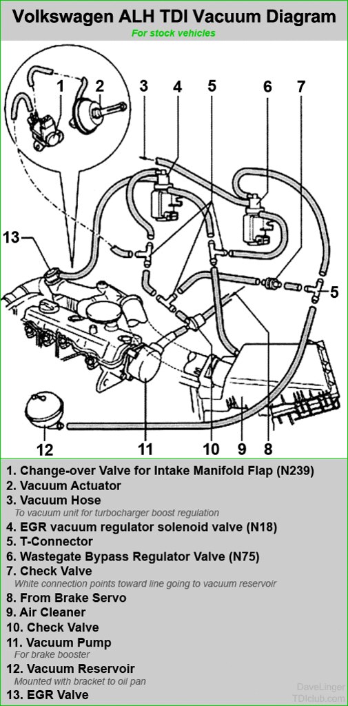
 - complete vacuum system, with the valves,vacuum lines and vacuum ball
 - fuel filter and fuel filter mount
 - passenger-side engine mount (I didn't need the dogbone mount, but you might)
 - dashpod and complete accelerator pedal with rheostat (cut off the pigtail leaving yourself a few inches of wire, you'll need that to wire it back up later. label well, it might be a while before you put this back together again)
 - in-car fuse-box and battery-top fuse-box
 - computer with both plugs. The smaller plug (which goes to engine management) is best uncut. The larger plug can be cut, but you must be very careful where. Any accidentally cut wire (like to the dashpod, eg) will create headaches and repairs later
 - starter. grab the pigtail that's plugged into it too
 - intercooler and all related pipes

There are pieces you can choose to include on top of this list. For example, if you are going to try to do cruise control, you will need the control arm from the cockpit, the speed sensor from the wheel and the brake sensor from the brake pedal. If you intend to use the dashpod for all gauges, you will need the speed sensor regardless. And, eventually, you will need to plan out how to get the right resistance range from your fuel level sender. I didn't do this, but I have thought about it. Do you want to try to get air conditioning running? I didn't but, if you do, you'll need that complete system (compressor/pump, hoses, the condenser on the radiator, etc) too.

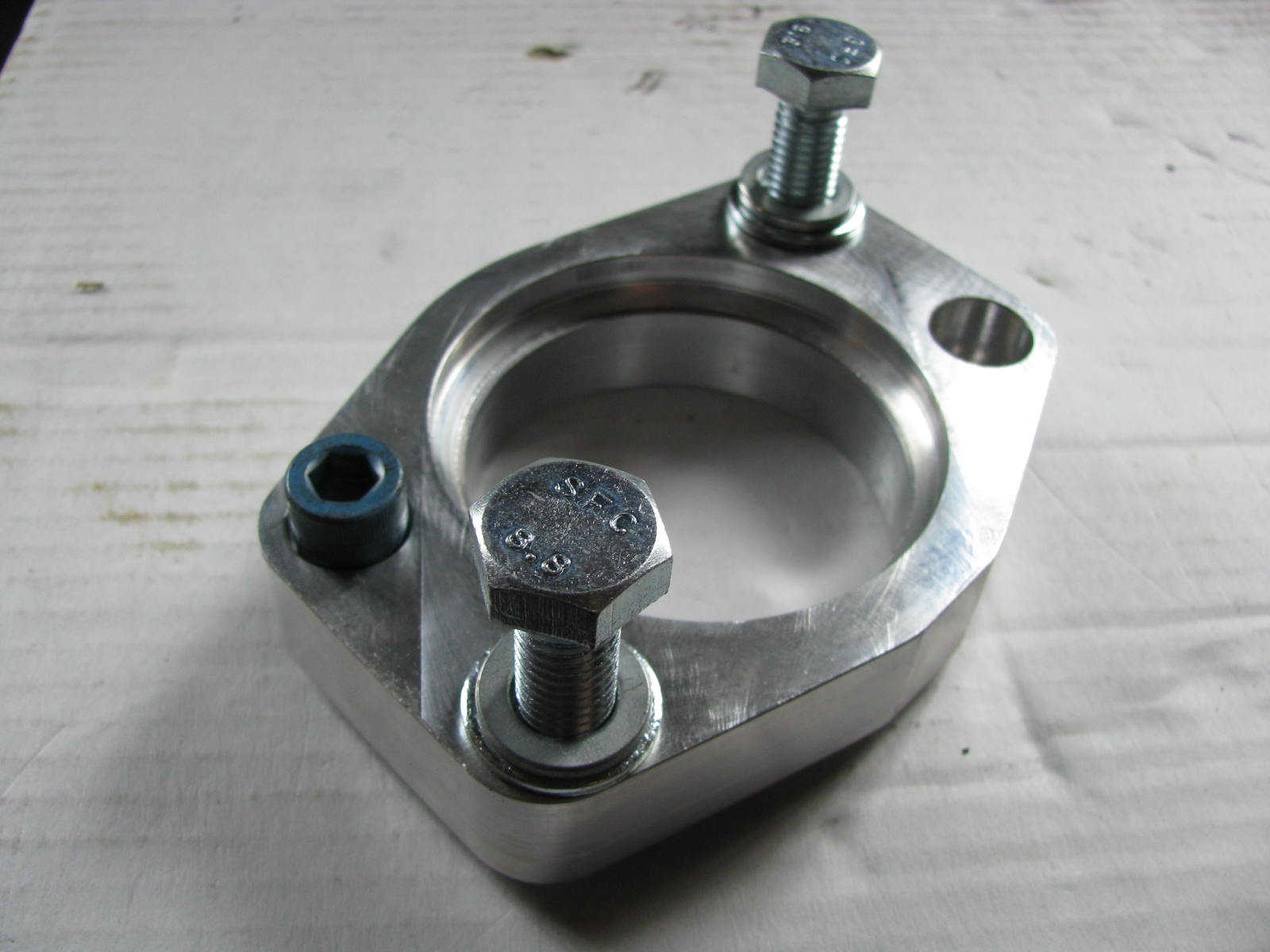
I found a donor with a little over 50k miles on it with all of those accessories plus some stuff I didn't need, shipped from GA for around $3500. The price has probably come way down, but the miles have probably gone way up. You may need to rebuild or replace some expensive systems (turbo, head) so plan accordingly. If your donor engine is coming from a wrecked car, you will probably need a $80US Van Gogh bracket (available from DieselGeek) since most of the time this point in the engine block is weakened or broken in a front-end collision. You will need a $70US starter adapter so the TDI starter can fit into your bellhousing. You can find them here. I suggest getting the OEM plug unless it is in the bundle of wires from your donor as I suggested above.

Engine Preparation
Once you have the engine on hand, I strongly suggest you go through it. If you aren't an expert, employ one. I had my friend Justin, the local TDI guru, go through it and then he did a timing belt job on it. By go through it, I mean really go through it. Pull the turbo and check for play. Pull a valve looking for burn marks. Shine a light into a cylinder (or all). Pull the oil pan looking for metal bits. Unless you knew the engine before you got it. Hours spent now will save days (and possibly an engine replacement) later.

I removed the exhaust gas re-circulation (EGR) stuff, and installed a "race" pipe. These currently run for around $150US, though I'm pretty sure I paid much less than that. You can find them here.  Making changes like this are easier when the engine is on the ground versus in the bus. Depending upon your application, and emission needs, you may not be able to meet your target without the EGR. I know that with B20 my bus produces far less pollution than it did with the old engine, but threads like this one have me considering putting it back in. Since this uses coolant to reduce the temperature of the exhaust gasses re-entering your engine (or uses exhaust to heat your coolant, depending on your perspective), this could be an issue if you are concerned about keeping the engine/coolant temperatures down. Your experience may vary; the only wrong choice is the uninformed one.

At this point, I would encourage contacting Kennedy Engineering (KEP) for an adapter plate and stage 1 clutch. When I bought them, the conversion kit (included flywheel) was $400US. It could very well have doubled by now, but the Van Gogh and starter adapter are about what I paid, so who knows? I am unable to see prices on the KEP website. If you are going to go big, with new nozzles and a bigger turbo, you may want to step up to the stage 2 clutch. The clutch will be heavier than the gasser clutch regardless, so consider your left leg and the stress on your clutch cable when you choose. I have no regrets with my selection (Stage 1).

Transaxle
When I first did my conversion, I didn't have any extra scratch around to think about the transaxle. I used the stock one. The gearing, especially at higher desired speeds, is way off. After I had the bus moving for a couple of years, and finacially recovered a little bit from my divorce, I had a transaxle built by AA Transaxle in Seattle. Darryl built me a trasnaxle based on the "CM" code from a 1975 bus with a taller 4.86 ring/pinion (like the Vanagon’s have) that is good for the Diesels with taller 3rd and 4ths. Into that case, we installed 1.14 and .73 gears for 3rd and 4th respectively. At the time, the prices were $500US for the core plus $320US per gear set plus $895US for the full rebuild for a total of around $2100 including shipping.

Bus Preparation
hatch. note notch cut out of support
With a known-viable engine on your shop floor (or sitting on a cart / tire / stand / scoot / whatever), you're ready to go after the recipient. Remove the old engine and transmission as a unit. This is documented in the Bentley and the Idiot's Guide in far better detail than I could provide. I recall the significance of draining the gasoline out of the tank when I hit this point, knowing that it was the last time gasoline would be in there. You may have a similar moment of realization. Whatever your motivation, this is a special moment. Separate the engine and transmission. Remove the battery and the starter. These will join the engine in the will-sell-later pile. You won't need the voltage regulator, so that can also go into that pile. But, you will want to keep track of (read: label well) the wire that feeds power to the reverse switch as well as the power source that leads to the front of the bus from the starter. I suggest leaving the starter trigger wire with the plug on it so you can easily identify it later. Or, cut it off and label the remaining wire well.

With the engine and transmission set aside, remove the fuel tank (See Pulling the Fuel Tank). If you retain the stock TDI location for the vacuum pump and don't modify the outlet flange (I recommend both after pursuing alternative solutions), you will need to modify the fuel tank (See Fuel Tank Solved). Since you are shifting from gasoline to diesel, you will at the very least want to have your tank cleaned and lined. You may not have a firewall anymore, so you may want to consider cleaning and painting the fuel tank bay and putting some paint on the tank itself.

When I did this conversion, I cut a large access hatch from above the engine bay. You don't have to do that, but I think you'll find maintaining the engine, even checking the oil and coolant levels far easier. Whether you do or don't, you will need to cut out a short section (less than a foot) of the support that runs across the underside of that back deck. Otherwise, the intake manifold will hit it once you have the engine installed. You can see the section cut out in the picture above. I intended to stiffen it, but never got to it. I have loaded tons of stuff onto the back deck and have never stressed this "lid" to the point where I thought about it. Your bus; your choice.

TDI meet Transaxle
adapter on with studs still in
Once the TDI has the flywheel off, the adapter can be attached and the transmission connected. The adapter can only go on one way, and it goes on first. Then, the pilot bearing goes into the flywheel and it is attached to the block. Add the pressure plate and clutch. Remove all of the pins and studs from the adapter plate. Now, mate the transmission, twisting it so the output shaft slides in and then rotate the transmission to align to the holes. Then, set the pins and studs through. I tried lots of other ways, but this was the only consistent way, and I have done this multiple times. This way takes a few minutes. Leave the studs in, and you'll be at it all day.

I'll stop here for today.

Next, I'll go through the various systems and how they were solved. As the posts are produced and released, I'll return to this post and hyper-link them below, and cross-reference as best I can.

Fuel System
Physical Mounting
Vacuum System
Air, Inter-cooler and Exhaust
Primary Electrical
Cooling
Secondary Electrical
ECU, dashpod and Sensors