Showing posts with label box. Show all posts

Tuesday, June 7, 2022

Returning to Hapy Sounds - Part 3

I think I've touched pretty much every other part of Hapy's sound system this winter/spring, so I guess it's only right to finish it up with improving the head unit install. Of course, no stereo entry is complete without some fun with wiring, so there's some of that too. I am still pushing hard to have the bus ready for camping season. So, while this may seem to be a departure from the shortest trip to complete, we can't go camping or long-distance driving without sounds. In a way, the ability to easily hear the stereo was what triggered the noise containment project. We just gotta have it.

How Did We Get Here?
planning the cut
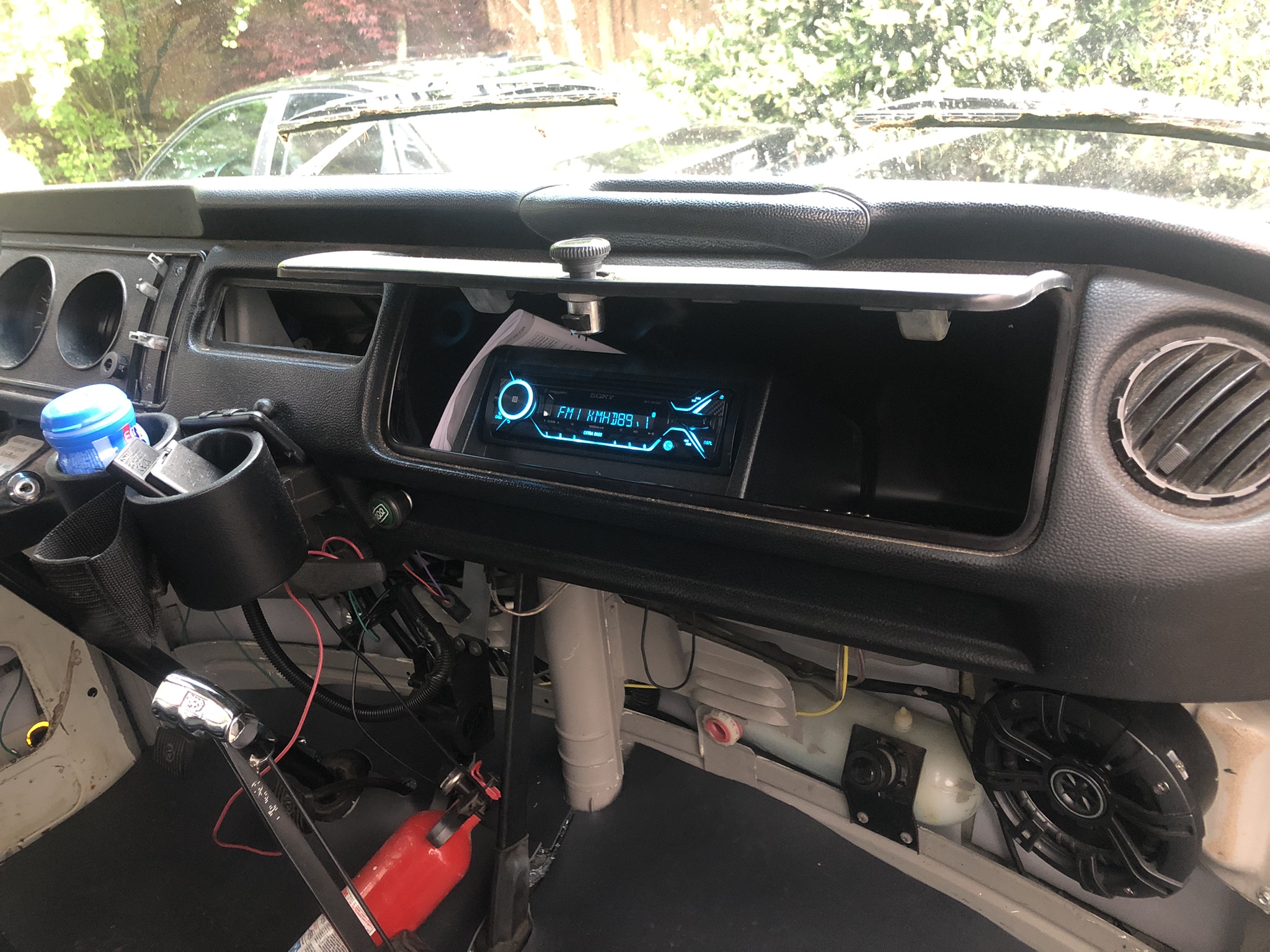
While I was working on getting sound deadener behind the original cardboard glove box, I decided to remove it for better access. I had already disconnected the luxury electrical set up for the electrical rough-in (See Ceiling Wire Rough In), so I simply unplugged the head unit that I had stashed in the glove box and pushed the plug out the hole I had bored in it. After emptying the remaining contents into a small cardboard box, I looked at the glove box. I discovered that the old cardboard box was holding on for dear life, and the removal of the support bar (Phillips screw on the underside of the glove box) did it in. The rear edge (front is front) that is pressed up against the dash had been all raggedy anyway, and once I started removing the box, that edge powdered off in chunks. So, I ordered one of those ABS plastic replacements. With the deteriorating original box in hand, I considered how I could more permanently mount the stereo when the new ABS box arrived. These were on back-order, like so many things these days, so I had to wait a while to complete this.

Solve the Head
mock-up with original box
I got a Metra Universal under-dash mounting kit (model 99-9000), and started fiddling with how that rectangular kit could fit into the rounded glove box. After several measure and test-fit attempts, it was fairly clear that hanging the stereo from the top of the box was not practical. The glove box was too shallow and the mounting kit too deep. I would have had to cut a large rectangle out of the rear of the glove box, and I'm not sure it would have fit right afterwards.

Back when I first got this head unit, I set the head unit in the glove box, on top of the molded shipping cardboard. It fit, and I could manage all of the buttons. Since hanging the box from above didn't work, I tried the kit upside down, mounting to the floor of the glove box. The kit was still too deep, but only by an inch or so. I measured, marked and cut an angle off the rear and it snugged right in. I confirmed that the stereo unit did not extend past the shortest point in the trimmed-down mount-box-thing. To mount the cut-down box to the glove box, things got interesting. I have demonstrated multiple times that I cannot manage to transfer measurements consistently. So, rather than swiss-cheese the underside of the box, I set the kit where I wanted it and marked two holes on the inside (blue tape, then a marker) of the box. I drilled out those 2 holes so I could align the rest of the box from below. I set the box such that the holes aligned and then held it in place with vice-grips while I marked the rest of the holes. Then, I drilled them out. Even then, the holes were not 100% perfect, so I expanded them where needed with a file. I added a hole at the rear of the glove box for the wiring pigtail with a hole saw and then attached the mounting kit with M3 bolts. That sentence took seconds to write, but the work took a couple of hours: tiny bolts + little finger room = patience needed.

Because, Wiring
marking holes
When I did the head unit the first time, I simply ran the power wire on the floor under the carpet. That was very Agile, demonstrated that having a stereo was a good thing, and that leveraging the luxury battery was a great call. So, since the stereo and the rest of the wiring in the bus was torn apart anyway, I changed the wire routing. Similar to the T12 front-to-back cable, I ran 2 sets of speaker cables and a power cable from behind the dash, down through the cable port behind the accelerator pedal and under the bus. I ran this collection of wiring along the frame and then found an existing factory hole (probably a drain hole) just inside of the passenger rear suspension up into the rock-n-roll bed. To keep things straight, the speaker wires were marked with tape (yellow-left, orange-right).

The yellow power wire was routed over to the driver side under the rock-n-roll bed and lightly tucked into place so it doesn't dangle into things and then integrated into the new fuse box (See Luxury Electrical Restored). Onto the speaker wires, I re-integrated the female wire connectors that I had before. One pair of two is under the rock-n-roll bed on the passenger side. Similar to the power wire, I tucked the wires under the rear edge of the bed floor so they stay out of the way. The other pair (recall there were 2 before) was sent through to the other side of the rock-n-roll bed up into rear of the formerly-fridge cabinet. Later, I may switch the female wire connectors to ports, but not today. At this point, I grabbed the floating remote rear speakers and plugged them in.

Back at the front of the bus, I integrated the various rear-speaker wires. Consider there's the pair that run up the A-pillar and to the rear over the sleeping area and the pair that now run under the bus to the rock-n-roll bed. The pair that run under the bus were the same as the pair that used to run along the floor. When I cut them, I marked them left-right. The pair that were sent up the A-pillar, however, were not. to figure out which one was which, I stripped one pair and clipped them together. Then, at the plug at the rear of the bus, I checked the plugs for continuity between the center-hole and the outer ring. One was infinite, the other was almost 0 resistance. 0 resistance is the winner, so I marked the end at the front with the same color tape (orange:right, IIRC) and then marked the other one. I spliced the remote speaker wire pairs together first, and then added the tiny wire from the stereo loom. I expect I will be adding an amp at some point, so I did not soldier them up. 

Putting it Together
note the mounting bolts
With the speaker wires integrated into the loom, the hard part was done. I spliced in ground and the yellow power wire and cleaned up the loom -to- front speaker connection. We were ready for install. The plastic glove box does not fit as easily into the dash as the old cardboard one does. I think it is a little larger, which really is fine. I needed and found a longer mounting screw (about an inch longer) for the support bar. To set the box in place, I found that suspending it in the support strap with the opening pointing up was most effective. Then, the box just tips into place. Since the box is bigger and less malleable, I focused on getting the bottom edge in the right spot, and let the top edge sit high. I sent the mounting screw home and the box doesn't wiggle at all.

I sent the wiring loom, the antenna cable and the wireless phone mic cord through the hole in the back of the glove box and plugged everything in. I took a quick glance at the fuse box and saw the tell-tale red LED telling me that I had a good circuit. Loving that fuse box feature. I set the stereo into the hole added a 10A fuse and fired up the local jazz station. After a few set-up steps on the stereo and burying the excess wire, the stereo is as complete as it needs to be for this Summer. 

So, the stereo is complete.... until I get a wild hair again to change it again. Like, wouldn't it be cool to have remote speaker plugs outside the slider so we can close the door without interrupting the music when set up for festivals or camping? Moments like this are when it is so obvious that this bus will never be done. There are always new ideas.

That's it for today. Thanks, as always, for following along-

Tuesday, December 28, 2021

Returning to Hapy Sounds - Part 1

In the midst of the Summer 2019, I added the ability to listen to music to Hapy, the 1972 TDI-powered microbus (See Making Hapy Sounds Part 2, for example). Today, I start my revisit with the front speakers. In this part of the front speaker improvement, I create very very small speaker boxes for a pair of 5-1/4" speakers with materials readily available at the hardware store; remove the speakers from the door cards and mount them into those speaker boxes; and last, get it all into the bus. Unlike most of my posts, the overwhelming majority of the measurements are in inches rather than mm. This is because here in the US, all of the published material about speakers is in inches. So, any information I put here can be more easily cross-referenced.

Why?
Diablo Royale pod
I guess it makes sense to start with answering the question "why are you making a change". There are a couple of reasons. First, the door cards that I made out of pressed cardboard are starting to fail. Unlike the original cards, the material I used was not designed for this purpose. So, over time, as some moisture appeared (this is the Pacific NorthWest, after all), the cards started to bend, and pull away from the doors. With the 5-1/2" speakers mounted in the lower part of the card, the card condition deteriorated more quickly as the speaker added a swing-weight whenever the door was opened or closed. So, when the door was closed, the bottom of the card (and the speaker) were not mated to the door, allowing the speaker to kind of hang in space a little bit.

I decided to replace the pressed cardboard cards with a laser-cut PVC set from WerksBerg. These precision-cut PVC cards are great, and many options are available, but a pre-cut hole for speakers is not one of them. I decided that I didn't really want to cut the PVC. This leads to our second reason: while the sound was okay, it wasn't awesome and maybe it could be better while driving. The only real upside to the speakers being in the doors was the added sound we got in the music festival camping lot when we opened the passenger door. When driving around, there was music, but it lacked some clarity. Of course, the road, engine and wind noise contributed, but that's another whole story... and solution path for another day. I think speakers just hanging in space (back not enclosed) negatively impacted the quality of the sound, and the cards were not going to last much longer.

Options
schedule 40 4" cap
So, if the speakers are not going to be in the door, what other options are there? There are a few. Some folks cut holes in the toe kick. This brings the advantage of having speakers facing you, but they are still down by your feet. Some bus owners replace the little fresh air vents with little speakers. This option moves the sound closer to your ears, which is great, but you lose those vents, and the only speakers that fit in there are super small (like 2" tweeters).

If you have a parcel shelf under the dash, you can set/mount speakers in boxes placed on the shelf. The shelf narrows on the outer edges, so speakers most likely fit best near the center of the bus, near the central air pipe. I don't have those shelves, but even near the center they do not look terribly deep. When I first bought Hapy, a prior owner (PO) had mounted small boxed speakers to the big metal air vent boxes. They didn't work, and the PO had taken the stereo with him so I pitched those speakers. Of these options, I do prefer rear-facing / under-the-dash locations over the door cards. The trick will be figuring out how to mount them, and exactly where they will provide sound best.

5-1/4" Thinking
test fitting 5-1/4 speaker
So, we start with figuring out a way to mount / hang speakers under the dash such that they won't get damaged yet they fling sound towards us. The 5-1/4" round speakers I have are kinda large for the space. Sure, 6-1/2" round speakers are bigger, and more common, so finding a speaker box or pod that fits the 6.5 is definitely easier. Still, I have the 5-1/4's and the smaller footprint will play to my advantage now, since the new location will be inside the cab, potentially near our knees.

Ever seeking cheap, yet effective, solutions, I constructed one. But, of course, not without checking out off-the-shelf options:
  • There is a guy (Diablo Royale) on eBay who makes plastic speaker pods in Texas. I bought a pair of his mounting pods for Oliver so I could mount the front speakers down by our feet, against the outer walls (See MGB Interior Panels - Part 1 or better yet MGB Gets Sound - Part 1). Diablo Royale had pods that fit 5-1/4" speakers, but they were still open-backed, $50US per pair and at least 6 inches across at the top by 4 inches deep. The base was at least 7 inches across. Looking at the under-dash, that would have been pretty ugly. Without a flush backwall, which would be nearly impossible with the contours up there, the sound would not throw as well. To make them fully enclosed / flush, I would have to construct a rear side.
  • There are MDF speaker boxes, wrapped in trunk carpet. These are also larger, but at least they have a back. The smallest ones I saw for the 5-1/4" round speaker were 8 inches square (or larger as rectangles) and 5 inches deep. If I had a parcel shelf, they might fit, but really only in the center since those parcel shelves get shallow as these near the door A-pillar.
better view of a
metal bracket attempt
Those are basically your off-the-shelf options. For the space we are targeting, they are not terribly good. So, we get out of the (speaker) box, and see what we can come up with. Our requirements are few: the speaker requires a 4-1/2" hole to sit into -and- it needs just under 2 inches (1-13/16 inches) from the mounting surface to the rear of the "box" for the cone and magnet.

It turns out that a 4" schedule 40 PVC pipe cap is a great starting point for a speaker pod. The one I found is 2 inches deep from lip to rear wall, but I saw deeper ones on the 'net. The inner diameter is 4-1/2 inches. I know; you're asking "but you said 4 inch cap". Yes, that's right. The schedule 40 4" cap refers to the industry standard 4" pipe, which is an approximation of the inner diameter of the pipe. Since the cap goes around the outside of that pipe, there is additional diameter to account for the thickness of a schedule 40 PVC pipe (here's a link for more dimensions). Neat, eh? Oh, and these are about 1/2 the price of the Diablo Royale pods at less than $15US each, made-in-USA, they are available at your local hardware store -and- they have a back wall.

5-1/4" Speaker to Cap
Once in hand, we need to figure out how to mount the speaker to it, and then how to mount the unit into the bus. I started with the second question first by moving the speakers around while playing the stereo. I concluded that the farther to the outside I could put the speaker, the better the overall sound. I resolved with placement directly below the dash vents. To mount, I bore a pair of holes through the cap, and mounted the cap/pod to the metal vent cover. Since the vent cover could be removed and replaced, I could use bolt/nut /washer fasteners instead of self-tapping or sheet metal screws. I think the nut-bolt combination creates a better, more reliable attachment.

plastic mounting tabs
For mounting the speaker to the cap/pod, I started with the smallest angle brackets I could find at the local Ace hardware store (3/4") when I got the caps. I also tried 1/2" brackets but they were no better. I probably could have super-glued something plastic, but that seemed flimsy. After a lot of drilling, cutting measuring and more cutting, I abandoned the 3/4" angles. I tried 1/2" angles, but they did not line up right with the speaker cover holes. I bought a set of angles online that had a channel, but even the smallest set like these were too large. I even tried constructing mounts with some scrap wood (1/2" wide and thick by 3/4" tall), but they were too bulky.
 
So, how did I resolve it? In true ghetto style, of course. While cleaning up my garage, I found a lid for one of those larger rectangular plastic storage tubs. The lip bent around 90* and extended about 3/4". With tin snips, I cut a series of pieces out, each about 1/2" wide and at least 1/2" into the top of the lid. This produced 8 little plastic "L" shapes to construct mounts out of. I marked and drilled holes, and then cut away the excess material with the snips. They are barely visible now, and once I wrap the pods with trunk carpet of some other fabric, they will mostly disappear.
 
5-1/4" Pod Wiring
With the physical mounting solved, I turned to wire routing. Ideally, I would have included a wiring cup. I omitted it because the flat bottom of the cap/pod will be pressed against the bus for mounting. Then, I thought about putting a cup on the side. I figured between the curvature and the shallow space within, it simply wouldn't work. So, instead, I drilled a small hole in the side of the cap/pod, and sent the pair of speaker wires through it. Leaving some slack in the wires within the cap/pod, I applied a blob of caulk into the hole to seal it back up.

Polyfill?
polyfill'd
My last step was adding some polyfill into the cap/pod. Simply, polyfill interrupts the sound wave moving on the back-side of the speaker when sound is produced by the cone. This interruption improves the projected sound out of the front of the speaker, and tricks the speaker into acting like it is in a larger enclosure: so, more bass. Using polyfill (or not) is kind of a religion with audio folks. I figure speaker enclosure manufacturers wouldn't use it if it didn't do something beneficial, and the 6x9 boxes I got for Hapy's rear speakers were polyfill'd. This cap/pod thing is super small for this speaker, so if it was going to do anything for a small speaker, this is the kind of scenario where it might. Still, the probability that I would really notice is virtually 0 (especially in the while-driving din), but I did it anyway. Ultimately, this cap/pod is about creating a safe means of mounting the speaker, with a hope that the sound is improved through it's proximity to the listener. The sound could not be measurably worse by moving it a foot closer in an enclosed cap/pod -versus- hanging in a loose, flapping door card down by your feet. Quite the opposite, I think it is much better. At least, it is set up to be.

isolation foam
When I get around to making the interior nicer with carpet and other fabrics, I will cover the cap/pods with whatever material I am otherwise using along that front wall so they visually disappear. Or, I'll simply cover them with trunk carpet. Before final assembly, I put some closed cell foam between the speaker cap/pod and the vent cover I mounted it to. This should help isolate the sound / vibrations a little bit. You can see the foam in the picture on the right as well as the markings I made to get the speaker aligned for drilling the mounting holes. Last, I simply plugged the wires into the speakers, set the speaker into the cap/pod, set the grill atop and attached it to the brackets. I took the assembly out to the bus and simply re-attached the vent covers with the speakers attached. The wires dangling from the cup/pods were tied into the existing front speaker wires that used to be in the doors, and then tucked away. I may apply a wire wrap to disguise them a little better, but I think they look good enough for now.

Testing
wired up and fired up
Because of my lack of a warm workspace where the bus fits, and a young puppy who can't be out in the cold for more than 15 minutes at a time, I still have not completed the install of the replacement seats. So, testing consisted of playing the stereo without moving the bus. Still, I think moving the 5-1/4" speakers made a difference. Considering that our legs no longer interrupt the sound waves, the speakers are about a foot closer to our ears, and the speakers are contained, there should be some benefit. Ultimately, I probably didn't need to move the 5-1/4's for sound improvement. It is absolutely possible that the open space behind the speaker in the door cavity actually helps the lower frequency sound form better. But, I didn't want to cut the new cards and this was kinda fun, and this was something I could mostly do in a warm garage, with a puppy underfoot.

That's it for today. thanks, as always, for following along-

Tuesday, June 22, 2021

MGB - Brake Booster Replacement

In my last post about Oliver, the 1978 MGB, I mentioned that the brake booster was the cause of a vacuum leak in the engine. This vacuum leak was causing cylinder #1 to run very lean compared to the others. Fortunately, Oliver has not seen much road time, so the engine should be fine. Regardless, today, I cover the fun of removing and then installing a replacement brake booster.

I would like to note that the body work on Zed came to a full stop when the Oregon weather predictably shifted back to cold-wet. For those who don't live here, we experience a wonderful donut-hole of beautiful weather in April/May smack in the middle of the cold-wet. The cold-wet returns for the month of June, usually lasting until Independence Day. So, I entertained myself with other projects, like this, while we waited for the weather to change back. After yesterday's high temps, I suspect the cold-wet is over until October.

Booster in an MGB
We start with where the booster lives in the small engine compartment of the MGB. The brake master cylinder, the clutch master cylinder and the brake booster all live together, attached to one another through the "pedal box": a rectangular steel box just in front of the firewall on the driver side. Closest to the rear is the clutch master cylinder. It is bolted to the back of the box with a lever extending into the box and attaching to the clutch pedal with a pin that is held in with a cotter pin. Attached to the front of the pedal box is the brake booster, with 4 1/2" nuts. This has a lever passing rearward, attaching to the brake pedal with a similar pin-with-a-pin design. To the front of the booster, the master cylinder is attached (2 nuts either 7/16" or 1/2"). Into the master cylinder a rod is passed from the brake booster.

You can imagine the brake action then: pedal is depressed which leverages against the clevis pin to press the lever into the brake booster. The brake booster converts some engine vacuum into more braking force which is then applied through the rod to the master cylinder.

Booster OUT OF an MGB
booster out
The Bentley manual has a step-by-step instruction for removing the brake booster, but I found the instructions to fall down. It started with removing the cover on the pedal box. I agree with that. It then described removing the clips for the brake lines leading to the master cylinder within the engine compartment. I agree with that. Then, it instructed to remove the bolts holding the brake master cylinder to the front of the booster. I also agree with that. At this point, the brake master cylinder can be slid forward off the booster-rod. By doing it this way, no air is introduced into the brake system. I likey.

Then, the instructions said to remove the cotter pin holding the clevis pin for the brake pedal to the leaver on the brake booster. This is not possible for anyone with adult male (and probably female) fingers for width and no one with child fingers for how deep you need to go. The gap between the side of the box and the partition which runs front-to-rear is not wide enough for fingers. I tried long needle nose pliers, but I concluded that even if I got the cotter pin free, and got the clevis pin off, I would not be able to re-install this way. So, I started my own path from here.

My plan was to remove the pedal box with the brake booster still attached and remove the booster from the pedal on my bench. Unlike the brake cotter pin, the partition is much wider on the clutch side, so my average-thickness fingers were able to remove both the cotter and clevis pins without too much difficulty. So, with the pedal disconnected, we remove the clutch master cylinder from the box by removing the 2 bolt/nut combinations that attach it from the rear.  Once removed, the clutch master  cylinder can be pushed rearwards out of the way. Next, we focus on the pedal pox. There are 2 bolts from the top, along the outer edge of the box nearest the centerline of the car. There are 3 bolts from inside the driver footwell going up. Last, there are 2 bolts from behind the dash running forward. Once all 7 bolts are out, the box is only held in place by gravity and the seal. Some light upward pressure on the brake booster and the unit pops free. Getting the unit out of the car took some wrestling, but I think this was more difficult because I could not see where the pedals were dangling. I found that by rotating the unit 90* clockwise helped the pedals to make it through the hole. had I read my old post about removing the pedal box (See MGB - Master Cylinders (Part 1)) or the post about the install afterwards (See MGB - Master Cylinders (Part 3)), I would have known to loosen the bolt fastening the clutch pedal so it dangled a little bit more. This would have made the removal much less of a muscle effort.

pedal box upside down on
workbench with old booster
Once the pedal box was out, it was a simple matter to remove the cotter pin and clevis pin between the brake pedal and the brake booster.... from the underside. I removed the remaining nuts on the brake booster, and started the install by performing the steps in the opposite order: attach the brake booster to the front of the pedal box. Thread the clevis pin through the lever and pedal, minding to include the washer before re-inserting the cotter pin.

Booster Back In MGB
With the unit in the same relative state of assembly as it was in when it was removed, I returned to Oliver to install it. I approached the install in the same manner as it was removed: rotated 90* so the booster was pointing across the engine. The pedals didn't fit, but with some rotating of the box and squeezing the pedals together, I could get them to fall through. Then, I wiggled and rotated the box, checking for cables wires and tubes from getting underneath until it settled in place. I decided that I would do the hardest first, so I did the clutch pedal/master first. I bolted the clutch master cylinder to the rear, after wiggling it around to fit, setting the lever alongside the clutch pedal. Then, I attached the pedal with the clevis pin and cotter pin. I found there was more play that I expected at this joint point, and concluded that I got the clevis pins backwards between the brake and clutch. Food for thought if you are doing this: the longer clevis pin is for the brake.

new booster in
With the clutch master cylinder tied in, I added the brake master cylinder to the front. This is much easier to get to. Once fitted, I started fitting the pedal box to the body. Because of the brake and clutch hard-lines, the pedal box is reluctant to move. I found that putting the 2 bolts through from the dash forward into the rear-most part of the pedal box allowed me to move the box into position. Once the bolt holes along the inside edge (2 of them, one 1/2" one 7/16") aligned, I set those 2 through. Last, I got back on my back inside the driver footwell and sent the last 3 7/16" bolts through the outer edge of the pedal box.

Brake Booster Hose
With the new booster on the pedal box and the pedal box in the car, all that remained was connecting the vacuum hose. I had oriented the booster upside down from the original so the vacuum nipple is on top, rather than below. I did this because of the significant heat source below the booster (exhaust) that is less present above. Also, the hose is much shorter and straighter from intake manifold bung to brake booster nipple. Wanting to avoid any possible issues with the original one-way valve on the intake manifold, I replaced it as well.

Re-Tune and Jetting
Because the old booster was creating a vacuum problem, I re-did the ColorTune tuning steps. Similar to the first time, I tuned using cylinders 1 and 3 but achieved a nice blue in both banks this time. I did swap out the idle jets (50F9 jets), but in order to find blue, I had the idle mixture screws further out than 2 full turns. I will drive Oliver around a little bit, but I think I may need to go up to 55F9 jets if the instructions in the SK Racing manual are to be followed. I noticed that the SK Racing product page describes the "pilot jet" in the carb set-ups they are selling today as 55. Assuming this is the idle fuel size, that's more support for trying 55F9 idle jets.

Since these SK Racing carbs are so similar to the side-draft Weber, here's another tuning link I found specifically for Weber. Notice how that article indicates the starting spot for the idle mixture screw is 2.5 turns out? That is about where mine are now. Curious. One last link, again on the much more plentiful Weber DCOE, but this time about some recommended jet sizes. It recommends the 50F9 idle jets for a late B like I just put in, so honestly, at this point, it will come down to a road test.

under the jet cover plate
Swapping out jets in this carb is seriously one of the easiest things I think I have ever done on a car. There is a cover plate on the top of the carb which is held in place with a slotted bolt. Once the cover is removed, the 4 jets (one idle per side and one main per side) are held in with slotted jet holders. The idle jets are the ones further from the engine / closer to the air filter. The holder threads out, and the jet is held in the holder basically with friction. The old jet slides out, the new jet pops in and you thread everything back together again.

The engine tune did not meaningfully change after the re-jet, so I concluded that the air-fuel mixture from the old jet was virtually the same. So either I removed a pair of 50F9 jets only to put in new ones or the old ones were a similar enough combination that they provided the same air-fuel at idle. At least I know what they are now.

All that is left is a drive... but wait! I didn't hook up the brake light switch. Well, I did, and after a few days of head-scratching trying to get the lights to illuminate, I realized that I had plugged it in wrong. The source 12V arrives in a dual plug, and the signal to the brakes departs through a single plug. I had thought the single plug was from the old carb-preheater, so I had failed to send either side of the switch to the brakes. Instead, I simply wired both sides of the switch to the 12V supply. Hahaha. Simple fix. Once the cars were shuffled so Oliver could get out past the herd, I did a longer test-loop. It did not take long to get the engine to normal operating temperature and he ran great. There was a slight stumble (bog) from dead stop, indicating that he was still a little lean. So, once back in the garage, I turned the idle screws about 1/8 a turn more rich. When I rev'd him from idle, I could not note a bog so I figure he is fairly close to tuned now. More road testing will confirm, and I expect I will fiddle with these screws as weather and altitude factor.

Thanks, as always, for following along-

Tuesday, April 2, 2019

Speaker Box Install Finish

I left off the sound system with some test fires and some lingering to-do's. Today's post covers the completion of those steps.

Shorter RCA Cables
The first and easiest to-do was replacing the RCA cables from the head unit to the amp. I originally used cables that were thick and over a meter long (about 4 feet total length). With the head and amp so close together, this left me with lots of extra cable looped all around. I found a vendor on eBarf and had 18" cables delivered. These were perfect, leaving me enough extra cable to maneuver things, but without a bunch of extra to deal with.

Ring Terminal Ground
original light location
note the fuel tank vent / hinge springs
When I first put things together, I didn't have a ring terminal for the ground wire. We were in the middle of a late-winter snowstorm, so getting to the corner hardware store was not in the cards. I didn't want to stop my efforts so I slapped together a ground using a washer and some electrical tape. It did the job, and once he weather improved, trading this hack-job for a real ring terminal was easier than trading out the RCA cables.

With those two things done, the front end of the system was complete. I had a couple of nagging issues in the trunk to deal with, though.

Trunk Light
Back in the boot, I had the speakerbox fit onto the little (less than 4 inches deep) shelf, and against the lots-of-holes-in-it rear fire wall. The speaker was propped up by an old sub woofer that I wasn't going to use. It served the purpose of showing how the speaker would sit, but that wasn't a viable long-term solution. What it revealed was that the trunk light, which sits in the center of the trunk opening furthest forward, would be mostly blocked by the box. It lit up the top of the box beautifully, but the trunk was now mostly dark. So, I moved it.

new light just above latch
The trunk light housing is held to the "beam" that runs over the top of the little shelf by 2 Phillips head screws (picture at right). With these removed, and the purple-circuit fuse pulled, the housing can be lowered. I set the bulb aside and pulled out the feeder-wires from the housing. Those wires were then back-fed through the openings in the body until they were hanging loose by the right-side hinge where the switch is. I cut the 2 wires around the midway point, and then started experimenting with new locations. I decided to mount it to the underside of the trunk lid, just aft of the mount-points for the MG medallion which sits on the trunk top side. There is a cross-member here which provided a place to put the screws through without creating through-holes.

I sent the wires from the housing through the trunk-lid cavity, and found I needed about a foot of wire to re-connect it to the switch. A few minutes of scrounging, cutting, wiring and taping later and the circuit was reconnected. I stuffed the wires into the trunk lid cavity and cable-tied the wire bundle closest to the hinge to the hinge so they wouldn't get hung up on future parcels in the trunk. I replaced the bulb, put the plastic cover on and replaced the purple circuit fuse. Tada! Light fills the trunk better than it did before and the light itself is not in your eyes anymore. I will need to take care with objects shifting in the trunk, though, since the housing is now down near the latch.

Strapping It Down
With the light solved, I needed to create a means of attaching the speakerbox to the car. I want the box to be easily removable, in case we want good sounds at picnics, or if I ever want to use it in Hapy. I also wanted to minimize ant further impact into the storage space in the trunk. So, adding to the little shelf or adding drop-feet to the box were not options. Instead, I thought through options to hold the rear top edge up and forward rather than extra support from below.

I got a spool of 1" nylon strapping. These are used on backpack shoulder straps or gym bags and are super strong. I cut 2 1-foot lengths, and looped one end of each around the tank vent / hinge-springs that run the width of the trunk opening at the front edge. These looped from above, with about 1" of overhang below. I super-glued the edge of the 1" overhang to the longer side, and tested by pulling on them. To these straps, I threaded on the female side of a nylon strap buckle. Now, I had something to attach to in the car, the speakerbox needed something too.

I bought some footman loops for the box-end. I put one footman loop on each end of the rear side of the box, 1.25 inches from the top and 2 inches from the edge. I repeated the nylon strapping process I did in the trunk with the overhang hidden against the box. I threaded the male end of the strap buckle onto these. After a little wrestling and fiddling, the box sets and is free-standing-ish. To install the box, I put the bottom front edge on the little shelf and then lift the box upright while holding the car-side straps to the sides. Once the box is upright, I click the buckles together.

There are always little things that could be changed or improved, but I think, for now, the work is pretty much done. I changed the way the wires connect through to the speaker for greater ease of install, for example, by adding in RCA connectors between the speaker and the speaker wires. That hardly warranted a post, but it was completed once the parts arrived.

Top Down Test Drive
We had a taste of spring with sunny skies and temps in the upper 60F's (about 20C) so Boo and I took Oliver out for a quick spin. I had installed the passenger seat (not post-worthy, it was a basic install with no discoveries nor bungles), so we were ready. Boo hadn't been on a ride except for a short drive down the street and back last summer so we were way overdue. I dropped the top, and pulled into the drive where Boo hopped in. We drove around the local neighborhood and easily chatted over the slight wind noise. We tested the sound too, and while it doesn't sound as good when it is sitting still in the garage, it sounds way better than I expected. The bass is full, the highs are present and the mid's cut through. Yes, there is wind shear, and some of the signal is lost, but most of that loss is filled back in when the volume is turned up. Boo and I agreed that the new seats are super comfortable, and the car would be perfect for a road trip. We just need a reason and a destination.

That's it for today. Thanks, as always, for following along--

Tuesday, March 19, 2019

Car that Goes Boom - Part 2

Continuing the fun from the last post about the amplifier install into Oliver. When we left off, we had selected an amplifier and an install location. I had concocted and fabricated brackets to support it, installed the amplifier and did some tests, both by sitting near it as well as a road run to verify the brackets held. Today, I will go through the wiring aspect and fire this thing up.

Wiring Rear
In the last post, I mentioned there are 2 methods for wiring signal to the amp. I used the pre-amp / RCA cables method. To achieve this, I first needed to find and label 6 RCA cables. I found a few old RCA cables from my A/V stash, but they were over a meter (4 feet) long. On each wire, I marked a (F)ront, (R)ear or (S)ub prefix and (Left) or (R)ight. I did this on both ends. Why? So no matter which end I was doing maintenance on (or replacing a component) I knew what the wiring was without having to jiggle wires or unhook the other thing to figure it out. On the amplifier end, I plugged the cables into flat 6-pin pigtails, keeping the F/R/S wires together. Next, I pulled the stereo out of the center console, and passed the RCA cables through. There are a few wires that need to be removed from the big plug in the back of the stereo, and the rest remain. Simply: all of the speaker wires need to be removed from the plug. Consider, the "signal-on" wire needs to be made available to the amplifier. I had not used it at this point, so I needed to add an extension so it would reach. With the RCA cables plugged into their correct holes in the stereo, the power, switched power, ground and "signal-on" wires connected, the stereo can get put back away. Last, I plugged the 6-pin plugs into their respective slots on the front of the amplifier, noting that "(F)ront" goes to channel 1/2, "(R)ear" goes to channel 3/4 and (S)ub goes to channel 5.

There is a 4-pin for the remote bass and "signal on" as well. The remote bass is a knob that I will install later. For now, it is tucked behind the center console near the driver side foot well, but it is wired. The signal on wire I had located was connected to this pigtail and heat-shrinked. To keep things clean, I zip tied the bundle of cables and wire together, and tucked them into protective wire wrap (like this) I picked up at Harbor Freight. The black wrap made the cables disappear. I routed the whole thing up and over the top of the amplifier before routing it behind the center console. This should keep the bundle out of the passenger's feet while still keeping the controls available for fingers.

Wiring to Speaker Box
clamped screwdriver as wire spool
Up until now, the wiring going to the rear of the car had run through the cockpit. I ran the 2 wires along the transmission tunnel on the passenger side. Now that I was adding another pair of wires, though, the cable had become too thick, and was making a lump under the carpet. So, I decided to route the speakers under the car. Again, leveraging protective speaker wrap (smaller diameter this time), I routed the wires for the 2 rear speakers plus the sub woofer to the front of the car through a wiring feed hole (mostly hidden by the sub box). I think it used to control the fuel pump because it has spade connectors in it. From there, the cable ran along the underside of the car with the other bundle of wires that run front-to-back all the way from the fuel pump to the starter.

Because of the location of the wiring hole in the trunk, I did not leave much slack in the wires back there. Instead, I considered ways I could get the wire bundle to stay up against the box. I decided to leave the cable wrapped almost all the way to the sub-woofer plug, and figure out how to tidy it more later. With the other ends of the wires for the speaker box hanging under the glove box, I was entering the final phase.

Wiring Front
$3 wire wrap protects
Out the back of the amplifier are 12 threaded-bolt wire mounts: +/- for both front (4), +/- for both rear (4), a pair for the sub (2), and one each for ground and power. Since I had done everything else so cleanly, I didn't like the idea of running a bundle of wires at the amplifier. For maintenance and ease of amplifier removal, I wanted something easier. Also, the only slam on this amp in the reviews was about these connections, so I wanted it to be set up once and then forgotten about. So, I got some multi-wire connectors from BritishWiring.com. With these connectors, it would almost look like it was part of the original MGB. Unfortunately, they don't sell any even numbered pins, so I used a 9-pin for the front/rear speakers and a 3-pin for the sub. I wired a few inches of wire from the amplifier to the male plugs (see the second picture from the top) and then wired the speakers and ground/power into the female plugs. That sentence was quick to write, but it took me a several hours of effort.

Wiring Power and Ground
Test fit - RCA cables too long
All I had left was the ground and power. I had intended to use the extra pin on the odd-numbered plugs. When I set out to do the wiring into the plug (see top picture) I quickly discovered that the 10 gauge power/ground wire needed for the amp were very different animals from the 14 gauge speaker wire I had in the rest of the plug. Quite simply: the 10 gauge was too thick to pin. So, I bought a 3rd 2-pin plug designed for a GM alternator from the local NAPA. It had male and female plugs on it, so I could cut it into two pieces and continue the plan. Similar to the other plugs, I put the male end on the amplifier side and wired the female end into the car. With a ring terminal on the black wire (ground), I leveraged the rear bolt from the amp mount. This was a solid ground, based on my connectivity and voltage tests. For the power, I ran a blue wire from the alternator, through a 10A bladed fuse and through the rubber-lined wiring hole in the firewall behind the glove box. This dropped the power supply nicely near the amp.

Once both were connected through to the plug, I was ready to plug everything in for a test. I think, ideally, it would have been better to wire the power into the battery, but the battery is behind the seats, so the wire run would have been longer, creating a greater likelihood of a short. I ran a couple connectivity tests to make sure everything was set to go, and then re-connected the ground on the battery.

Test Fire
I had already identified a couple of things that needed to be changed, but with everything hooked up I wanted to see if it worked before I started changing things. So.. in short, the speaker wires were moved from the head to the amp, the amp was wired with power and grounded, and the power-up signal from the head was routed into the amp remote switch. Everything should be set to go. With the battery still connected to a tender, I slapped the face back onto the head unit and turned it on. All the lights came on, but I couldn't hear anything. I turned the stereo way up and could barely hear sound, so I concluded the gains on the amp were too low. Second attempt: turn the stereo back down to single digits and turn up the gains. Now we have sound.

With Rush's "Spirit of the Radio" cranking, I set the various levels so Getty Lee's bass snapped and growled, Neil Peart's drums punched and Alex Lifeson's guitar sang. It sounds so good inside the cabin with the top up. Once I get out, the sound really doesn't travel outside of the car as much as I would have expected. Of course, once the top goes down, things will change. This leaves one last test: driving at speed with the top down. That will have to wait until Summer. In the meantime, I tried the classical station for a different sound signal and it sounded really good... but not as good as Rush did. There's just something about Rush. Maybe it's the punchy bass. Whatever it is, the next test will be an early Dead show, like, maybe, the Music Box from Feb 1968, and then a wall-of-sound show.

Thanks for following along. I still have to install the passenger seat into Oliver, and then I may start working on the interior door panels. Or, maybe, I'll just finish the trunk. I don't know. I'll see how I feel when I get to the garage.

Tuesday, January 15, 2019

Speaker Box Finished

After months of sporadic work, the speaker-box is finally finished. Today's post will go over the final few things I did to complete it.

Where Were We
test fit with rear panel in place
When I last posted on this thing, I closed the post with "...after a bunch of hours with the Dremel and hand planer, the wall mate-points are smooth enough where I think it will be hard to see how out-of-alignment they are once covered with carpet. That's what I'll do for next time... as well as get some wiring in, and the 6th side of the box attached... and then the edges planed.... ". I had 5 of the 6 sides attached and planed, baffles installed. I felt ready for the final side, carpet, and wiring.

One Wire
The route from the wire cups on the right side of the box (front-is-front, so the "right side" assumes the 6x9 speakers face forward and the 10-inch sub faces rear) to the left 6x9 speaker needed to go through a baffle. The other wires, for the sub and the right speaker, were not so constrained. So, I left those wires out until after the carpet was on. For the one, left, speaker, though, I drilled a hole through the baffle, threaded speaker wire through, and then routed it along the bottom seams to the wire cup. I glued it into place so it wouldn't flop around, nor create an internal vibration. My concern about a vibration may seem a little without basis, but I thought with a wire that was running the length of the box, it might find it's way against the sub woofer cone. Regardless, a few extra minutes and some wood glue was a very small cost. I filled the speaker wire drill-hole with glue on both sides as well.
papering for pattern

Rear Panel
With that one wire installed, the rear panel could go on. When I set the panel in place, I could see gaps that couldn't be resolved with wood screw force; I needed to plane the edges of the side panels. To get things flush, I started by setting the panel on, and marking the high points on the sides with a pencil, and then planing those areas down. I repeated this process a few times; each time taking less material between checks. I was not aiming for perfection, rather close enough to fit where I could make up the difference with torquing down with wood screws. Otherwise, I would have spent many hours clowning with perfection. As it was, I spend about an hour planing before spreading generous wood glue along the edges and setting the panel in place. I swiftly applied wood screws around the edges, using more screws on this panel than on the others to get it to set flat.

carpet pattern
I tested the seams with a flashlight, shining it from inside the box (hand through the sub-woofer hole) to confirm that the seal was good. To my surprise, it worked quite well. Maybe having a pilot hole every few inches isn't a totally bad idea. Once the glue had dried, I filled the holes with spackle, waited for it to dry, sanded it flush and repeated 2 more times to make sure the holes were smooth enough to not be noticeable through carpet. I probably over-revved on it a little bit, but I'd come this far, and spent so much time on it now, a few extra minutes was not going to make much difference.

At this point, I painted the outside of the box black. I wanted to make sure the box was sealed, though afterwards I was concerned that I might have made it harder to attach the carpet. My thought about painting was that if I jacked the carpet, any open spot would be black instead of raw MDF, so it would not be as obvious.

Carpet
carpet cemented
With all of the panels in place and all of the pilot holes filled, I was ready for carpet. I found some basic black trunk carpet online for about $8US for a 4-foot by 5-foot rectangle. This was about twice what I needed, but I bought extra with a plan to carpet the trunk of the MG with the same stuff eventually. So... how to carpet a box? Off hand, it sounds simple: you have 6 sides, so cut 6 pieces of carpet, glue them on. Yeah.. that creates 12 seams. I wasn't going to carpet the bottom, so it would have been 5 pieces of carpet and 8 seams, but still, that's way too many.

Instead, I mocked up a single piece of carpet that was shaped like a "T" using paper to construct a pattern (see pictures). Imagine the "T" upside down. That long side ran along the bottom edge of the rear and the two sides. The vertical part of the "T" wrapped over the top of the box and down the front. I cut the vertical part of the "T" wider by 1/2 an inch on each side so the edges of the top on the right and left sides would fold down and get covered by the side pieces when they wrapped around. This created 2 seams: one on each side along the top edge and down the front... and each seam was double-thick for a 1/2 an inch Once the box was installed into the trunk of the MG, you couldn't see them, and the seams are facing away from anything else in the trunk so the edges won't catch.

The carpet was attached to the box with DAP contact cement. This is nasty stuff, so I did this on my front porch under the overhang. Wear disposable clothes, and gloves because if the glue gets on, it doesn't come off. I followed the directions, thoroughly covering all 5 sides of the box (no carpet on the bottom, just black paint), as well as the inside of the carpet. Well, I did that best I could on carpet with a paintbrush. Using a glass tabletop as a guide for keeping the bottom edge flat and using my thumbs to mark where the sides were, I started applying the carpet to the rear of the box. Contact cement adheres on contact (hence, the name), so you really have one chance to get it right. I was able to get it lightly attached while checking the angles and had to adjust it once. After that, though, I started pressing it down into place, wrapping from the rear over the top to the front, leaving the sides flapping. Then, I brushed contact cement onto the little 1/2 inch flaps, waited a few minutes and then pressed the sides into place. This part of the assembly was probably the most nerve-wracking, knowing that misalignment during this process would make the whole thing look amateurish. Which, if I hadn't spent so much time on it, I would have been fine with, but now, I wanted it to look good.

Cut In
wire cups and 6x9's in
The contact cement needs at least 24 hours to cure. I waited a day for the stink to dissipate and then moved the box into the garage for a couple of days. Once I was confident that the cement was solid, I took an exacto knife and cut in the holes. I started with the wire cup holes, cutting across the diameter of the hole first and then laying the edge of the knife against the hole in the wood to direct the cut of the carpet. This worked very well, and allowed me to cut all of the holes without any mistakes.

Installs
With the holes exposed in the carpet, I was in the final stretch. I did the final wiring first: Laying out a length of wire for the sub and the right speaker, attaching wire ends and heat-shrinking. To these wires, I attached the wire cups, set the cups in the holes and then screwed them in place. The 6x9 speakers are held on with nuts, so the bolts which protrude from the box needed to be cut free first, but otherwise the wiring was straightforward and the speakers went in without issue. The sub-woofer had barely been out of it's box since I purchased it. It wired up and installed relatively easily, though. I needed to pilot the holes for the bolts through the carpet, and I did that by pushing a roofing nail through from the outside. Once bolted into place, I set the protective grill in place, and the box was done.

The construction could not be complete without installing and test-firing. So, I took the box out to Oliver and set it in place. It fit without difficulty, and the speaker wires easily reached the wire cups on the side. You can see the extra wire on the far side of the box in the picture here. There remains work ahead for wiring up an amp and wires for the sub, so I'll address the extra speaker wire then. In the meantime, I fired up the stereo (local metal station was joyously playing Ronny James Dio), and verified that all 4 speakers were running.

That's it for today. This post contains work effort that spanned a few weeks, completing New Years Day. I intend to paint the bottom of the box with some flex-seal so we can use the box outside, but that will wait a while. In the meantime, I'll be enjoying the sounds, and eventually getting an amplifier installed so I can power the sub.

Thanks, as always, for following along.

Tuesday, December 18, 2018

Even More on that Speaker Box

This speaker box has become quite the project. I swear, if I look back on the number of hours I've spent on this thing, it will rival the hours spent rebuilding the front end of the MGB. Anyway, more progress to update.

Baffling
testing only-angled idea
In my last post about the speaker box, I mentioned adding in some extra support along the edges. I'm sure it was helpful, but when I thought about how much air would be moving around the inside of the box, I got concerned about how the sub-woofer speaker would have air-influence over the 6x9's and vice-versa unless I created some kind of barrier between them. I had initially planned to do that, but this project has lingered on for months now, so I had almost abandoned it. I had some time and some left over materials, so I constructed a couple interior walls to isolate the 3 speakers from each other.

wiring cup
I initially thought about something simple: one wall per side that ran at an angle from the rear wall to the front wall. There's a dark picture to the right that shows what that would have looked like. This would have been easier, but consumed a lot of air space that probably should be available to the sub-woofer. To maximize the air space available to the sub-woofer, I changed to an an angled wall from the front face back parallel to the 6x9 speaker angle until it was clear of the rear of the 6x9 speaker magnet (this was about 3-1/2" long by just over 9-1/2" tall). I connected a wall from that point parallel to the rear/front walls to the side. This left little excess air-space for the 6x9, but the sub needs all the air volume I could bring it in this small box. As it is now, I am at the low-end of the air volume recommended by the manufacturer.

Cutting and Fitting
baffle glue drying
With the walls cut with an old-skool hand saw (I make crap-cuts with power tools), I shifted to test-fitting. The extra supports in the corners required cut-outs in the baffles. You can sort of see the square-ish cut outs in the corners in the picture on the right. The left-side baffle wall fit perfectly though the right side did not. From this, I discovered that some of my early work was not 100% square/perfect. So, some additional trimming was needed on the right side. Still, things looked good so I drilled one hole per baffle to hold the 2 pieces together and glued them.

To support the inner wall baffles, I took a couple small pieces of cut-off left-overs and placed a support along each of the inside of outer walls. I was able to rest the parallel-to-rear-wall baffle against this support to hold it straight as well as for an extra surface for glue.

Shaping
I had planned for 3 wire cups on the right side of the box. I bought these cups from Crutchfield, and used a hole-saw to mount them. The orientation of these cups becomes interesting when we consider the interior baffles I'd just built. I had 2 cups set side-by-side for the left and right 6x9 speakers and one below it for the sub. You can just make out the left-side hole in the picture below. This speaker cup orientation seemed intuitive. Once the baffle was set in place, wiring into the cups will be compromised. So, I had to pull out the Dremel again, and shave down a gentle curve behind 2 of the cups so there would not be any pressure on the wiring once all the various pieces were together.
smoothing the edges

With the baffles shaped, I glued them into the box. Once the glue had dried overnight, I assessed the gaps, and plugged them with wooden kabob skewers... and more glue. Basically, I determined the length of the gap, and cut a thin skewer to length. I then squeezed the skewer with pliers until it was thin enough to fit into the gap. With a thin slotted screwdriver, I pushed the filler material into the seam, and repeated until the gap was completely filled with wood and then slathered it with glue. I then ran a thin bead of glue along every seam to make sure the 5 sides and the baffles were sealed.

At this point, I decided to fix the misaligned outer edges with the Dremel and a hand planer. Ideally, it would have lined up perfectly. If I build another box, I'll take much more care to align just one hole per side for the screw, so the sides fit much better. I did that with the inner baffles, and they aligned far better. Anyway, after a bunch of hours with the Dremel and hand planer, the wall mate-points are smooth enough where I think it will be hard to see how out-of-alignment they are once covered with carpet. That's what I'll do for next time... as well as get some wiring in, and the 6th side of the box attached... and then the edges planed.... yeah, this project got a little out of hand. But it keeps me distracted without pulling a car off the road.

Thanks, as always, for following along.

Tuesday, December 4, 2018

More on that Speaker Box

I've continued to tinker on the box I started over the Summer (see MGB Gets Sound). Today's post covers some of the headway.

Sub Hole
I had about 2 hours of forecasted rain-break on a Saturday that also coincided with a reasonably good game of college football. So, I was torn, but I figured that I could do something on the box on the back patio and sort of keep track of the game through the sliding glass door. Yes, this sounds like a set up that ends with a board sticking out of said glass door, but actually, it all went relatively well. I started with measurements to find the exact center of the rear of the box. Centering on that with a compass, I drew a 9-inch diameter circle to cut. First, I set the panel on the box with the drawing side facing in, so I could check my spacing, and sure enough, that would have been a miss. Because of the bump in the center of the rear frame of the MGB, I have a corresponding bump in the box. To account for that, I need to slide the 9 inch hole towards the top by a half-inch or so. Another quick turn with the pencil, another upside-down check and I'm ready to cut.

way too many pilot holes around the
edge: don't do that
I drilled a pilot hole with a drill bit that was just larger than the saw blade. Then, I made the mistake of thinking that cutting the hole on a bias rather than at 90* was a good idea. Big picture, I may have retained a little more meat of the MDF, but it created a lot more fit challenges. Anyway, I cut the circle and test fit the subwoofer (still in the plastic bag to protect it from the dust). Yeah.. it fit through the top fine, but hung-up on the inner part of the circle because of that bias. To remedy, I attacked the inner lip with various tools: a file, the Dremel, sandpaper.. Eventually, the inner edge widened out and the sub fit. Word to the reader: don't cut on a bias; follow the directions from the sub-woofer manufacturer and trust that when they say the hole needs to be x in diameter, they mean both the top and bottom edges unless otherwise stated. With the sub capable of fitting in the box, I switched back over to the 6x9's.

Re-enforcement
The sub-woofer sites stress re-enforcing the edges of your box because of the force the speaker will exert upon it. I used some of the scrap MDF from the box construction to brace the corners. I've toyed with more bracing in the middle of the box. I may hold off and see how it performs before gluing the rear panel, and sealing my fate.

6x9 Fiddling
I had 2 things I needed to resolve with the 6x9's. First, the box needed threaded studs on the outside so the 6x9 could be attached and replaced from the outside. For this, I found some 1" long bolts that came with some kitchen drawer knobs. These are thin enough to easily fit through the mounting holes on the speakers, but don't protrude too far past the MDF edge to present fitting issues later. Best of all, I have 8 of them. So, I pulled one of the 6x9's from the rear firewall, test fit in the box holes, marking where the mount holes are and set it aside. A few quick runs with the drill, and I was threading the bolts through from the inside. I test mounted the speakers, and they will work great. I will need to be careful about carpeting, though, as the bolts really don't stick out very far. I may need to trim the carpet at the speaker edge rather than wrap through the hole. We'll see.

I then pulled the 6x9's out of the box and started test fitting the box into the trunk of the MGB. Post-assembly, the box is a smidgen taller than space would allow. Enter the Dremel again. I shaved down the front corners to fit under the fuel tank vent lines, and, after a couple hours of fiddling, I was able to get the box flush against the rear firewall. Once I had the box exactly where I liked it (dead center), I reached through with a Sharpie and marked where the 6x9's would need new cut-outs in the rear firewall. Recall that this firewall had been cut up pretty badly by the PO and I slapped together something to make it less crappy. Now, with these new holes, it is PO-level of crappy again. I'll need to do something eventually to make it nicer. Anyway, I cut along the Sharpie lines with my jig-saw. With the speakers back in the box, I set the box into the trunk against the firewall, wired up the speakers with the version 2 wires and tested the system.

We have sounds again. I spent most of a Saturday getting this far. I'll post next time on getting the rest ... or maybe just a little more headway... done. Thanks, as always, for following along-