I think I've touched pretty much every other part of Hapy's sound system this winter/spring, so I guess it's only right to finish it up with improving the head unit install. Of course, no stereo entry is complete without some fun with wiring, so there's some of that too. I am still pushing hard to have the bus ready for camping season. So, while this may seem to be a departure from the shortest trip to complete, we can't go camping or long-distance driving without sounds. In a way, the ability to easily hear the stereo was what triggered the noise containment project. We just gotta have it.
How Did We Get Here?
 |
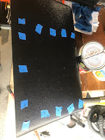
| planning the cut |
While I was working on getting sound deadener behind the original cardboard glove box, I decided to remove it for better access. I had already disconnected the luxury electrical set up for the electrical rough-in (See
Ceiling Wire Rough In), so I simply unplugged the head unit that I had stashed in the glove box and pushed the plug out the hole I had bored in it. After emptying the remaining contents into a small cardboard box, I looked at the glove box. I discovered that the old cardboard box was holding on for dear life, and the removal of the support bar (Phillips screw on the underside of the glove box) did it in. The rear edge (front is front) that is pressed up against the dash had been all raggedy anyway, and once I started removing the box, that edge powdered off in chunks. So, I ordered one of those ABS plastic replacements. With the deteriorating original box in hand, I considered how I could more permanently mount the stereo when the new ABS box arrived. These were on back-order, like so many things these days, so I had to wait a while to complete this.
Solve the Head
 |
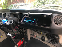
| mock-up with original box |
I got a Metra Universal under-dash mounting kit (
model 99-9000), and started fiddling with how that rectangular kit could fit into the rounded glove box. After several measure and test-fit attempts, it was fairly clear that hanging the stereo from the top of the box was not practical. The glove box was too shallow and the mounting kit too deep. I would have had to cut a large rectangle out of the rear of the glove box, and I'm not sure it would have fit right afterwards.
Back when I first got this head unit, I set the head unit in the glove box, on top of the molded shipping cardboard. It fit, and I could manage all of the buttons. Since hanging the box from above didn't work, I tried the kit upside down, mounting to the floor of the glove box. The kit was still too deep, but only by an inch or so. I measured, marked and cut an angle off the rear and it snugged right in. I confirmed that the stereo unit did not extend past the shortest point in the trimmed-down mount-box-thing. To mount the cut-down box to the glove box, things got interesting. I have demonstrated multiple times that I cannot manage to transfer measurements consistently. So, rather than swiss-cheese the underside of the box, I set the kit where I wanted it and marked two holes on the inside (blue tape, then a marker) of the box. I drilled out those 2 holes so I could align the rest of the box from below. I set the box such that the holes aligned and then held it in place with vice-grips while I marked the rest of the holes. Then, I drilled them out. Even then, the holes were not 100% perfect, so I expanded them where needed with a file. I added a hole at the rear of the glove box for the wiring pigtail with a hole saw and then attached the mounting kit with M3 bolts. That sentence took seconds to write, but the work took a couple of hours: tiny bolts + little finger room = patience needed.
Because, Wiring
 |
| marking holes |
When I did the head unit the first time, I simply ran the power wire on the floor under the carpet. That was very Agile, demonstrated that having a stereo was a good thing, and that leveraging the luxury battery was a great call. So, since the stereo and the rest of the wiring in the bus was torn apart anyway, I changed the wire routing. Similar to the T12 front-to-back cable, I ran 2 sets of speaker cables and a power cable from behind the dash, down through the cable port behind the accelerator pedal and under the bus. I ran this collection of wiring along the frame and then found an existing factory hole (probably a drain hole) just inside of the passenger rear suspension up into the rock-n-roll bed. To keep things straight, the speaker wires were marked with tape (yellow-left, orange-right).
The yellow power wire was routed over to the driver side under the rock-n-roll bed and lightly tucked into place so it doesn't dangle into things and then integrated into the new fuse box (See
Luxury Electrical Restored). Onto the speaker wires, I re-integrated the female wire connectors that I had before. One pair of two is under the rock-n-roll bed on the passenger side. Similar to the power wire, I tucked the wires under the rear edge of the bed floor so they stay out of the way. The other pair (recall there were 2 before) was sent through to the other side of the rock-n-roll bed up into rear of the formerly-fridge cabinet. Later, I may switch the female wire connectors to ports, but not today. At this point, I grabbed the floating remote rear speakers and plugged them in.
Back at the front of the bus, I integrated the various rear-speaker wires. Consider there's the pair that run up the A-pillar and to the rear over the sleeping area and the pair that now run under the bus to the rock-n-roll bed. The pair that run under the bus were the same as the pair that used to run along the floor. When I cut them, I marked them left-right. The pair that were sent up the A-pillar, however, were not. to figure out which one was which, I stripped one pair and clipped them together. Then, at the plug at the rear of the bus, I checked the plugs for continuity between the center-hole and the outer ring. One was infinite, the other was almost 0 resistance. 0 resistance is the winner, so I marked the end at the front with the same color tape (orange:right, IIRC) and then marked the other one. I spliced the remote speaker wire pairs together first, and then added the tiny wire from the stereo loom. I expect I will be adding an amp at some point, so I did not soldier them up.
Putting it Together
 |
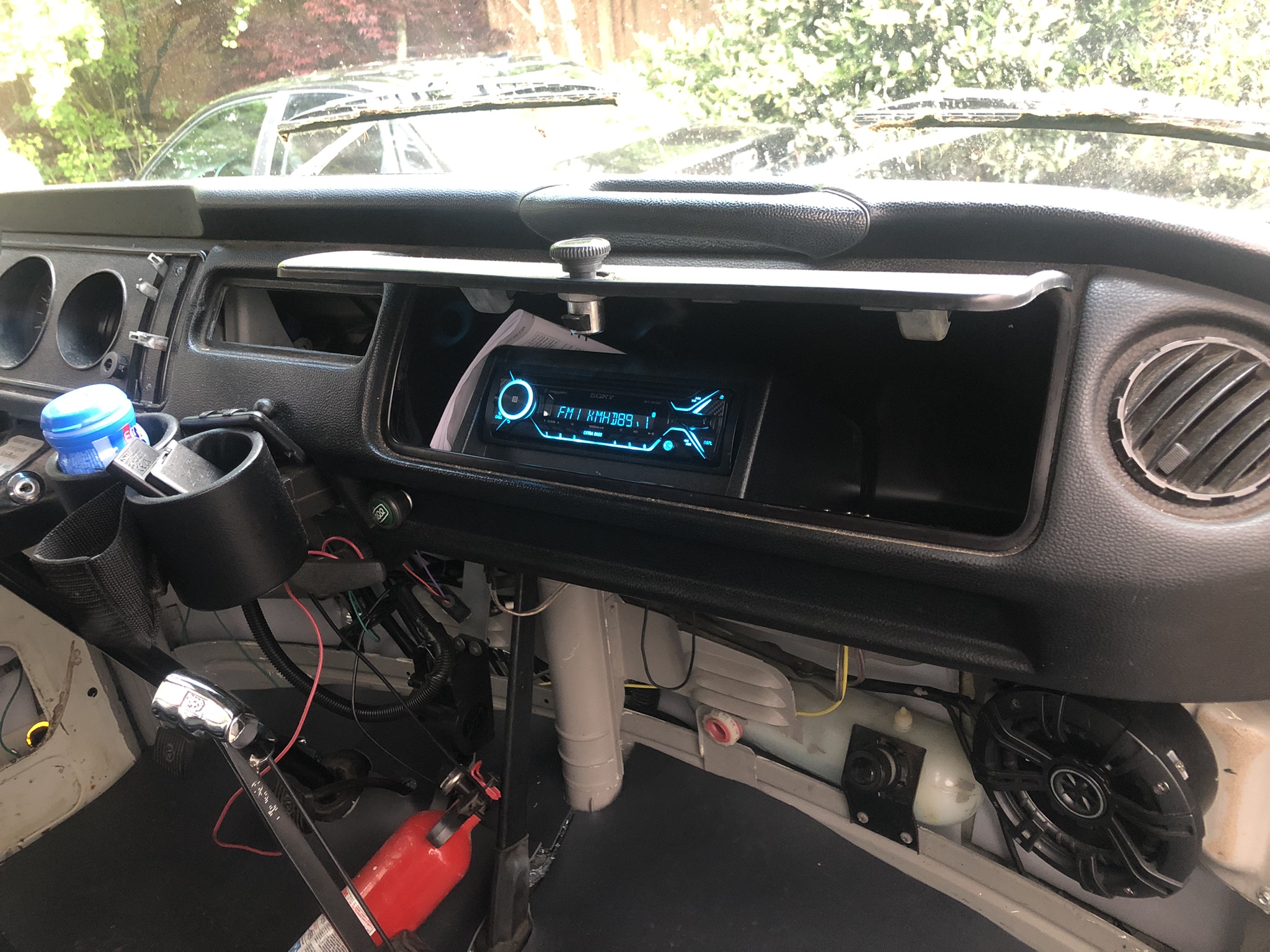
| note the mounting bolts |
With the speaker wires integrated into the loom, the hard part was done. I spliced in ground and the yellow power wire and cleaned up the loom -to- front speaker connection. We were ready for install. The plastic glove box does not fit as easily into the dash as the old cardboard one does. I think it is a little larger, which really is fine. I needed and found a longer mounting screw (about an inch longer) for the support bar. To set the box in place, I found that suspending it in the support strap with the opening pointing up was most effective. Then, the box just tips into place. Since the box is bigger and less malleable, I focused on getting the bottom edge in the right spot, and let the top edge sit high. I sent the mounting screw home and the box doesn't wiggle at all.
I sent the wiring loom, the antenna cable and the wireless phone mic cord through the hole in the back of the glove box and plugged everything in. I took a quick glance at the fuse box and saw the tell-tale red LED telling me that I had a good circuit. Loving that fuse box feature. I set the stereo into the hole added a 10A fuse and fired up the local jazz station. After a few set-up steps on the stereo and burying the excess wire, the stereo is as complete as it needs to be for this Summer.
So, the stereo is complete.... until I get a wild hair again to change it again. Like, wouldn't it be cool to have remote speaker plugs outside the slider so we can close the door without interrupting the music when set up for festivals or camping? Moments like this are when it is so obvious that this bus will never be done. There are always new ideas.
That's it for today. Thanks, as always, for following along-


No comments:
Post a Comment