Showing posts with label front. Show all posts

Tuesday, July 19, 2022

Zed Body Kit Start

Last Summer, amid the economic restart following the CoViD-19 shutdowns, I ordered and received a fiberglass bodykit for a Datsun 280ZX. It arrived too late to be wrapped into the body work, and I ran out of warm weather anyway. Today, I restart the body work on Zed (1979 Datsun 280ZX), with hopes for having Zed painted before I run out of summer this year. Even though there is considerable Summer left, my time is less available this year than in years past. Boo has injured her arm/shoulder, preventing her from moving it per Dr orders, so I am doing a lot more not-car stuff these days (read: lawn care, housework, etc) which all take precious minutes. 

Back to Start
bumper gap set
While Zed was parked under a canopy / car port all winter, that is not the same as sitting in a climate-controlled garage. Or even an unheated garage. Rain does not fall straight down, and wind blows organic material around. So, when I was ready to focus on Zed, I had a few steps to just get him back to where I had left him last Summer. I had been using his interior as a staging area for parts and boxes while working on the sound/noise contain effort in Hapy (1972 VW camperbus). So, logically, the first thing to do was to vacate the interior and shop-vac it out.

Next, the body panels needed a cleaning. Rather than use a hose, I hand washed him with a bucket and scrubber sponge. Still, I was unable to free some of the green haze that had appeared. He would need a sanding in order for the next layer of paint to adhere anyway, so I left what remained to be addressed by the sanding. I pulled out the body kit that had been stashed inside and cleaned it too.

Front Fenders
d-side bumper
I had spent some time wrangling the front bumper last Summer. I could only get so far because I had not completely solved for the fenders yet. Now that the driver fender was ready, I could move forward. I started by simply mounting the fenders with M6 stainless bolts. When I fastened the bottoms, the fenders ballooned out into their proper shape. I had not realized how flat they had been sitting until then.

Rear Bumper
The rear bumper was the closest to being complete, and after spending so much time on just getting things back to the way I thought they were, I wanted a win. I started fiddling with it and I discovered that I had not really prepared the steel rear bumper hidden within: it had rust spots on it and it was still dirty from when I bought it. More cleaning with a bucket and a scrubber and then sanding, rust treatment and a shot of Rustoleum got it ready enough for use. No, I don't really like the idea of Rustoleum on this project anymore than I think you do, but this will protect the bumper well enough, and once I sand a key into it for the epoxy to grip into, the paint choice really won't matter much anymore. After the paint cured (or 48 hours later...), I re-attached the bumper, making sure the height was completely flat, with the same distance between the tail body panel and the top of the bumper. It is into things like this that so much time is lost. Bolting on a bumper takes, like 10 minutes. Getting it exactly height-right, took more like 30.

p-side bumper
Once the steel bumper was set, I returned the fiberglass bumper to position to get it exactly where I wanted it. After some time spent fiddling with it, I was able to set the bumper such that the gap is the same across the rear, from corner to corner, and the seams along the rear quarter panel were consistent as well. I drilled a hole inside each wheel well near the top of the bumper and set it for good with a pair of M4 bolts. With the height set, I set the spread (tilt in or tilt out of the bottom of the bumper) of the lower edge. I controlled this with a second set of holes lower in the panels. Again, I set 2 M4 bolts through the bumper into the rear wheel well. I may eliminate some of these bolts later, after the epoxy sets.

Side Skirts
setting the spread
With the rear bumper looking good, I shifted forward to the little skirtings that run under the doors. I was not 100% convinced these were necessary when I bought the kit, but now that I have them roughed in, I like them. These kits are one-size-fits-none. While that was not really true with the rear bumper, it was definitely true with these side skirts. The length is quite good, and the fit into the wheel wells was almost perfect. I say almost, because I had to cut a small chunk out of the top of the passenger side skirt for it to fit. The issue with these skirts is with the little lip that runs the length of the door jam. These are designed to sit on the outermost edge of the door threshold, but the design has 2 problems. First, the lip is fairly thick so the door does not easily close on top of it, if the door is set at the right height. Second, and perhaps more important, the lip is not at the correct angle from the outer edge of the skirting. So, if you set it in place on that outermost edge, either it is in the right spot, but completely blocks the door -or- the whole skirting curls under the car too much, not aligning with the fender lines and looking horrible. I resolved by cutting off the lip with a hacksaw. Yes, that is a rather destructive move. I considered all the plastic panels on the ToyoTruck and the panels that run under the doors do not have a lip hanging on the door sill. These will now be a same.

fun with Bondo
With the lip removed, I was better able to control the angles. Similar to how I managed the rear bumper, I first set the height by getting the under-the-door edge just a smidge below the door opening. I set the height temporarily with clamps and then bored holes, used more M4 bolts to hold the tops in place.  I added a bolt on each side, near the leading edge of the door, to hold the section of the skirting which will attach to the front fender in place. I will use this bolt for setting the epoxy, but will remove it, or cut the head off, after the epoxy sets. Next, I set the spread so the rear outer edges aligned with the rear bumper lower leading edges. Because of how the skirts were constructed, this left a small gap at the top rear of the skirt. If I pressed the top against the side of the car, the bottom of the skirt would stick out too far. The picture below shows how it lined up. Because of the curve of the body, it is not immediately visually clear that the bottoms align, but they do. 

Body Fill the Gaps
d-side skirt rear
Around the internet, Bondo is a four-letter word. No one admits to using it, but practically everyone does in some capacity. If I were a master fiberglass guy and had all the time in the world, I might have built-up the trailing edges of the side skirts with fiberglass. That would have been the "right" way to do it. I don't have that skill, nor the materials, and, like I indicated at the top, I really don't have that time. So, I chose Bondo, and went full-on ShadeTree with it.

I have the panels attached exactly where I want them, held on with bolts. I don't want to remove them apply some material grind some down, re-attach, wash-rinse-repeat, in hopes of getting it right. That could take all Summer and still might not look that great. I want to apply filler to the fiberglass but not create a Bondo-bond with the side of the car. To resolve, I grabbed some non-stick spray from my kitchen and shot the steel body panels where I needed to fill a gap. I then cleaned the fiberglass with oil/grease cleanser, leaving the non-stick on the steel and I filled the gaps with Bondo. Is this how a pro would do it? I sincerely doubt it. Did it work? It worked well enough to define the lines. Once teh Bondo set up, I freed the panels, leaving them loosely attached. There was not any Bondo stick to the steel. I sanded things smooth and did another pass to get the seams really clean. Last summer, I tried to resolve the don't-stick by taping plastic to the steel, but no matter how well I set the plastic, there were minute folds which appeared in the dried Bondo. The non-stick spray left a predictably smooth line.

Sanding
body sanding fun
I re-attached the rear bumper and the side skirts after sanding the Bondo smooth. Then, I set into sanding the entire car with 320-grit. As I mentioned above, simply cleaning the body was not enough. Besides, I chose to not sand the primer last year, believing it would better protect the paint over the winter. It needed to be sanded before the next coat, be it more primer or color. I will be priming the fiberglass body panels anyway, so I may shoot primer on the rest. I'll decide that later.

I am about 2/3 done with the sanding of the whole body (fiberglass and steel), working from the rear forward. Once the sanding is complete, I will be setting the height of the front bumper ends, and perfecting the front bumper seams like I did with the rear bumper and side skirts. After all that, the fiberglass will be removed one last time for priming.

That's it for today. Thanks, as always, for following along-

Tuesday, January 25, 2022

Returning to Hapy Sounds - Part 2

I have spent some time improving the stereo set up in the bus when time has permitted. In a prior posting (See Returning to Hapy Sounds - Part 1), I described my effort to move the 5-1/4" speakers from the falling-apart door cards into small speaker boxes/pods constructed from a pair of schedule 40 4" pipe caps. These caps, now speaker pods, were attached to a removable piece of the vent system, so they are about knee-height and facing rearward. Today, I add another front speaker improvement.

Dash Speakers
image from FastFab
When these buses were first sold, there was a speaker mounted under the dashboard, pointing up at the windscreen, if you got the radio option. Regardless, the dash was constructed the same way, with perforations near the center of the dashboard top, a screw hole at the dash center-point near the windscreen and two mounting tabs underneath. While you could create something to hold a speaker, or a pair of speakers, leveraging the 2 tabs and the screw hole, a fabrication company already has. FastFab, based in La Hambra, CA, created a basic panel (product page here) into which a pair of 3-1/2" speakers can be mounted.

It should be noted, however, while the image on the product page, also appearing on the right, appears with rubber feet on the left side (which would fit into the mounting tabs), a mounting screw on the right side and speakers in-between... none of these are actually part of what you are buying. For $30US, you get a plain piece of bent metal with some holes bored into it. The product page does say that it does not include mounting hardware. However, in good faith, they could have included a picture of what you are actually getting. Simply, I was and remain unimpressed. I concluded it would probably take me more than an hour to make something similar and it probably wouldn't look as nice. I had it in-hand, so I moved forward with it.

3-1/2 Speakers
For speakers, I got a pair of 3-1/2 inch Kicker speakers. The model matches the 5-1/4 inch speakers I have mounted in the speaker pods I built in the last post, so the 3-1/2's should pair well. These cost me about $60US delivered, and they arrived with mounting hardware and wiring bits, but no grills. Since the dashboard has the perforations, and these speakers are going to mount inside the dash, grills are unnecessary. Crutchfield indicated on their website that these 3-1/2 speakers are an easy stock-swap replacement, where you re-use the stock grills, and that is why a grills are not delivered with the speakers.

I noticed that the panels had some sizing issues almost immediately after I started pairing the speakers with it. There are 2 misses: the mount holes, into which the black screws would ordinarily go to hold the speaker to the panel, are too large. So, the black screws which arrived with the 3-1/2 inch speakers could not be used. Second, the 2 large holes that the speakers are to set into are slightly too large. So, the speakers fit, but they shift around and will not sit cleanly without spending some time tweaking. When you combine these 2 design misses with the non-existent mounting bits, there is little actual value being delivered by these panels other than the bends and holes are in the right places.

Mount Speakers to Panel
speakers on panel
Unlike the picture on the product page, I chose to set my speakers through from the top, rather than suspend them from the bottom. This way, if one or more of the bolt/nut combinations fail, the speaker will not fall out of the panel. If I mounted it from below, loose fasteners could cause a speaker to drop out. Since the supplied black screws were not usable (panel holes too large), I found 4 gold-colored bolts in my home-electrical bin. These bolts had been for the copper grounding wire in electrical outlets. I had 4 nuts that fit, so away we go. As I mentioned earlier, getting the speakers to set just right them took some fiddling, but once they were set, and the bolt/nuts tightened, the panel was about ready for install. I like how the gold bolt heads match the gold centers of the speakers. In cases like this, it's better to be lucky than good. I added a couple of small pieces of foam on either side of the front mounting screw hole as well as on the mounting feet on the panel. This should reduce any vibration transmitting from the panel to the bus and vice versa. The foam on the feet became quite compressed from my use of clothespins to hold the foam in place, but they actually fit perfectly into the mounting tabs.

Dash Back to Black
Before I set the panel into the bus, I wanted to black-out the dash top. A prior owner had painted it gloss white, and that was the way it was when I bought Hapy. The glare on bright days was remarkable. So, when I replaced the windshield a few years ago due to age-related glazing, I painted the dash flat-grey like the rest of the interior of the bus. This was a considerable improvement, but there is a reason most cars have a black dash top: least daylight glare. I found a rattle-can of satin black in my garage, so after taping off the vinyl cover and the windshield seal, I shot what I could reach. There are areas that cannot be reached with a spray can, however: the vertical or nearly-vertical strips cannot be "seen" by the spray no matter the angle you hold the can. To get them color-consistent, I needed to hand-paint them with a short foam brush. This is kind of fun, actually. You can only see what you are doing through the windshield, so you blindly paint a little, run around to the front to see what you did and then repeat.

dash cover product image
I got to thinking about the noise in the bus, and how I want to reduce opportunities for sound to bounce off hard surfaces. The metal dash is a great example of one of those hard surfaces. So, after the painting efforts described above, I bought a DashCare dash cover. Knowing that the dash has contours to it, I paid the extra $5US for the faux suede, "DashSuede", rather than the standard thicker carpet model. This also "is low knap for a flat, low glare finish and will have high-low shading effects typical of Suede material". Once the sun returns, we'll see how "low glare" non-reflective it is. Since it has a thin foam core, it may help reduce reflected sound. I don't expect much, but every little bit helps. For now, this cover sits in a box, waiting for the projects to conclude.

Wire It Up
I stripped and prepped the wires before mounting the center panel. I figured I would have a hard enough time simply reaching the wires, and I was right. When I did the 5-1/4 speaker install, I knew I had these coming. So, I had spliced in a second stretch of speaker wire per speaker, so they were simply dangling when I brought the panel over. I simply routed the wire from the driver side under the dash and over the e-brake mechanics, dropping down into the passenger side foot well. In the picture on the right, here, I had the driver side wired in, using the passenger-side Sprinter seat as a work surface. Notice that the driver side is not installed yet. Still waiting... still waiting.
 
At this point, I had the wires and the speakers in a panel, so I simply I wired the speakers up: left -to- left, right-to-right. I suppose I could have tried to mix them up, but I didn't think there would be much left-right separation with the speakers so close together, so it didn't really matter. Either way, there are a pair of speakers pushing the left signal and a pair pushing the right. It is important to have all the speakers running on the same signal wiring to have the same resistance. Otherwise, sound levels will be inconsistent between them. By using the same manufacturer and the same series within that manufacturer, the sound will be as consistent as I could manage.

Mount Panel to Bus
Depending on how much crap you have under the center section of the dash of your bus, this could be anywhere from simple to very complicated. A few years ago, I had force-stuffed a rectangular plastic box into the original radio hole, and Hapy had some random wiring otherwise. I yanked the plastic box out, with a plan to do a better install later. Negotiating around the wires just took a ltitle patience. Once clear, the 2 feet set into the 2 mounting tabs towards the rear and the panel swings forward and up. I threaded a black screw that had delivered with the speakers through the hole in the dashboard and through the mount hole on the panel. I found that I had to start the threads on that screw first, and tighten down most of the way, before setting the feet. Otherwise the feet would pop off the little tabs. In fact, I got the front (front is front) screw almost all the way down and then swiveled the panel slightly to get the feet to set in the tabs. Then, I tightened that list little bit. As I wiggled the unit, there were no indications that the speakers were touching the underside of the dash.
 
Fire It Up
Once it was all put together, we were ready to test. As pronounced an improvement we realized when I moved the 5-1/4 speakers, adding the 3-1/2 speakers into the center of the dash was even more significant. The sound is very present now, with LOTS of mid and upper range, but the real test will be on the road with the noise of the engine, the drive-train, the traffic and the tires competing for our ears. Between the small 3-1/2" speakers and the very shallow pods for the 5-1/4" speakers, there was not as much bass as I like (I like a LOT of bass). I found that the head unit had reset while I had the power shut off, so the bass-boost was turned off during initial tests. Once I turned it back on and faded more signal to the rear, the bass came through and the bus is full of sound. Still, if you do something similar, it is reasonable to expect that the 3-1/2 speakers will push more high and mid than bass. I am looking forward to a road test to see if we lose the bass to road noise, forcing, perhaps, a sub into the mix.

That's it for today. Thanks, as always, for following along-

Tuesday, December 28, 2021

Returning to Hapy Sounds - Part 1

In the midst of the Summer 2019, I added the ability to listen to music to Hapy, the 1972 TDI-powered microbus (See Making Hapy Sounds Part 2, for example). Today, I start my revisit with the front speakers. In this part of the front speaker improvement, I create very very small speaker boxes for a pair of 5-1/4" speakers with materials readily available at the hardware store; remove the speakers from the door cards and mount them into those speaker boxes; and last, get it all into the bus. Unlike most of my posts, the overwhelming majority of the measurements are in inches rather than mm. This is because here in the US, all of the published material about speakers is in inches. So, any information I put here can be more easily cross-referenced.

Why?
Diablo Royale pod
I guess it makes sense to start with answering the question "why are you making a change". There are a couple of reasons. First, the door cards that I made out of pressed cardboard are starting to fail. Unlike the original cards, the material I used was not designed for this purpose. So, over time, as some moisture appeared (this is the Pacific NorthWest, after all), the cards started to bend, and pull away from the doors. With the 5-1/2" speakers mounted in the lower part of the card, the card condition deteriorated more quickly as the speaker added a swing-weight whenever the door was opened or closed. So, when the door was closed, the bottom of the card (and the speaker) were not mated to the door, allowing the speaker to kind of hang in space a little bit.

I decided to replace the pressed cardboard cards with a laser-cut PVC set from WerksBerg. These precision-cut PVC cards are great, and many options are available, but a pre-cut hole for speakers is not one of them. I decided that I didn't really want to cut the PVC. This leads to our second reason: while the sound was okay, it wasn't awesome and maybe it could be better while driving. The only real upside to the speakers being in the doors was the added sound we got in the music festival camping lot when we opened the passenger door. When driving around, there was music, but it lacked some clarity. Of course, the road, engine and wind noise contributed, but that's another whole story... and solution path for another day. I think speakers just hanging in space (back not enclosed) negatively impacted the quality of the sound, and the cards were not going to last much longer.

Options
schedule 40 4" cap
So, if the speakers are not going to be in the door, what other options are there? There are a few. Some folks cut holes in the toe kick. This brings the advantage of having speakers facing you, but they are still down by your feet. Some bus owners replace the little fresh air vents with little speakers. This option moves the sound closer to your ears, which is great, but you lose those vents, and the only speakers that fit in there are super small (like 2" tweeters).

If you have a parcel shelf under the dash, you can set/mount speakers in boxes placed on the shelf. The shelf narrows on the outer edges, so speakers most likely fit best near the center of the bus, near the central air pipe. I don't have those shelves, but even near the center they do not look terribly deep. When I first bought Hapy, a prior owner (PO) had mounted small boxed speakers to the big metal air vent boxes. They didn't work, and the PO had taken the stereo with him so I pitched those speakers. Of these options, I do prefer rear-facing / under-the-dash locations over the door cards. The trick will be figuring out how to mount them, and exactly where they will provide sound best.

5-1/4" Thinking
test fitting 5-1/4 speaker
So, we start with figuring out a way to mount / hang speakers under the dash such that they won't get damaged yet they fling sound towards us. The 5-1/4" round speakers I have are kinda large for the space. Sure, 6-1/2" round speakers are bigger, and more common, so finding a speaker box or pod that fits the 6.5 is definitely easier. Still, I have the 5-1/4's and the smaller footprint will play to my advantage now, since the new location will be inside the cab, potentially near our knees.

Ever seeking cheap, yet effective, solutions, I constructed one. But, of course, not without checking out off-the-shelf options:
  • There is a guy (Diablo Royale) on eBay who makes plastic speaker pods in Texas. I bought a pair of his mounting pods for Oliver so I could mount the front speakers down by our feet, against the outer walls (See MGB Interior Panels - Part 1 or better yet MGB Gets Sound - Part 1). Diablo Royale had pods that fit 5-1/4" speakers, but they were still open-backed, $50US per pair and at least 6 inches across at the top by 4 inches deep. The base was at least 7 inches across. Looking at the under-dash, that would have been pretty ugly. Without a flush backwall, which would be nearly impossible with the contours up there, the sound would not throw as well. To make them fully enclosed / flush, I would have to construct a rear side.
  • There are MDF speaker boxes, wrapped in trunk carpet. These are also larger, but at least they have a back. The smallest ones I saw for the 5-1/4" round speaker were 8 inches square (or larger as rectangles) and 5 inches deep. If I had a parcel shelf, they might fit, but really only in the center since those parcel shelves get shallow as these near the door A-pillar.
better view of a
metal bracket attempt
Those are basically your off-the-shelf options. For the space we are targeting, they are not terribly good. So, we get out of the (speaker) box, and see what we can come up with. Our requirements are few: the speaker requires a 4-1/2" hole to sit into -and- it needs just under 2 inches (1-13/16 inches) from the mounting surface to the rear of the "box" for the cone and magnet.

It turns out that a 4" schedule 40 PVC pipe cap is a great starting point for a speaker pod. The one I found is 2 inches deep from lip to rear wall, but I saw deeper ones on the 'net. The inner diameter is 4-1/2 inches. I know; you're asking "but you said 4 inch cap". Yes, that's right. The schedule 40 4" cap refers to the industry standard 4" pipe, which is an approximation of the inner diameter of the pipe. Since the cap goes around the outside of that pipe, there is additional diameter to account for the thickness of a schedule 40 PVC pipe (here's a link for more dimensions). Neat, eh? Oh, and these are about 1/2 the price of the Diablo Royale pods at less than $15US each, made-in-USA, they are available at your local hardware store -and- they have a back wall.

5-1/4" Speaker to Cap
Once in hand, we need to figure out how to mount the speaker to it, and then how to mount the unit into the bus. I started with the second question first by moving the speakers around while playing the stereo. I concluded that the farther to the outside I could put the speaker, the better the overall sound. I resolved with placement directly below the dash vents. To mount, I bore a pair of holes through the cap, and mounted the cap/pod to the metal vent cover. Since the vent cover could be removed and replaced, I could use bolt/nut /washer fasteners instead of self-tapping or sheet metal screws. I think the nut-bolt combination creates a better, more reliable attachment.

plastic mounting tabs
For mounting the speaker to the cap/pod, I started with the smallest angle brackets I could find at the local Ace hardware store (3/4") when I got the caps. I also tried 1/2" brackets but they were no better. I probably could have super-glued something plastic, but that seemed flimsy. After a lot of drilling, cutting measuring and more cutting, I abandoned the 3/4" angles. I tried 1/2" angles, but they did not line up right with the speaker cover holes. I bought a set of angles online that had a channel, but even the smallest set like these were too large. I even tried constructing mounts with some scrap wood (1/2" wide and thick by 3/4" tall), but they were too bulky.
 
So, how did I resolve it? In true ghetto style, of course. While cleaning up my garage, I found a lid for one of those larger rectangular plastic storage tubs. The lip bent around 90* and extended about 3/4". With tin snips, I cut a series of pieces out, each about 1/2" wide and at least 1/2" into the top of the lid. This produced 8 little plastic "L" shapes to construct mounts out of. I marked and drilled holes, and then cut away the excess material with the snips. They are barely visible now, and once I wrap the pods with trunk carpet of some other fabric, they will mostly disappear.
 
5-1/4" Pod Wiring
With the physical mounting solved, I turned to wire routing. Ideally, I would have included a wiring cup. I omitted it because the flat bottom of the cap/pod will be pressed against the bus for mounting. Then, I thought about putting a cup on the side. I figured between the curvature and the shallow space within, it simply wouldn't work. So, instead, I drilled a small hole in the side of the cap/pod, and sent the pair of speaker wires through it. Leaving some slack in the wires within the cap/pod, I applied a blob of caulk into the hole to seal it back up.

Polyfill?
polyfill'd
My last step was adding some polyfill into the cap/pod. Simply, polyfill interrupts the sound wave moving on the back-side of the speaker when sound is produced by the cone. This interruption improves the projected sound out of the front of the speaker, and tricks the speaker into acting like it is in a larger enclosure: so, more bass. Using polyfill (or not) is kind of a religion with audio folks. I figure speaker enclosure manufacturers wouldn't use it if it didn't do something beneficial, and the 6x9 boxes I got for Hapy's rear speakers were polyfill'd. This cap/pod thing is super small for this speaker, so if it was going to do anything for a small speaker, this is the kind of scenario where it might. Still, the probability that I would really notice is virtually 0 (especially in the while-driving din), but I did it anyway. Ultimately, this cap/pod is about creating a safe means of mounting the speaker, with a hope that the sound is improved through it's proximity to the listener. The sound could not be measurably worse by moving it a foot closer in an enclosed cap/pod -versus- hanging in a loose, flapping door card down by your feet. Quite the opposite, I think it is much better. At least, it is set up to be.

isolation foam
When I get around to making the interior nicer with carpet and other fabrics, I will cover the cap/pods with whatever material I am otherwise using along that front wall so they visually disappear. Or, I'll simply cover them with trunk carpet. Before final assembly, I put some closed cell foam between the speaker cap/pod and the vent cover I mounted it to. This should help isolate the sound / vibrations a little bit. You can see the foam in the picture on the right as well as the markings I made to get the speaker aligned for drilling the mounting holes. Last, I simply plugged the wires into the speakers, set the speaker into the cap/pod, set the grill atop and attached it to the brackets. I took the assembly out to the bus and simply re-attached the vent covers with the speakers attached. The wires dangling from the cup/pods were tied into the existing front speaker wires that used to be in the doors, and then tucked away. I may apply a wire wrap to disguise them a little better, but I think they look good enough for now.

Testing
wired up and fired up
Because of my lack of a warm workspace where the bus fits, and a young puppy who can't be out in the cold for more than 15 minutes at a time, I still have not completed the install of the replacement seats. So, testing consisted of playing the stereo without moving the bus. Still, I think moving the 5-1/4" speakers made a difference. Considering that our legs no longer interrupt the sound waves, the speakers are about a foot closer to our ears, and the speakers are contained, there should be some benefit. Ultimately, I probably didn't need to move the 5-1/4's for sound improvement. It is absolutely possible that the open space behind the speaker in the door cavity actually helps the lower frequency sound form better. But, I didn't want to cut the new cards and this was kinda fun, and this was something I could mostly do in a warm garage, with a puppy underfoot.

That's it for today. thanks, as always, for following along-

Tuesday, September 28, 2021

Zed's Slow Crawl into Fall

It's time for another update on the slow-moving restoration effort on the 1979 Datsun 280ZX lovingly called "Zed". Completely unrelated to Zed, Nemo, the 1997 Audi A4 was sold to a family friend. While he is no longer a permanent resident of our driveway, I expect there will be some ShadeTree adventures as he is improved upon.

Where Were We
p-side front fender gap
We entered the Summer with the goal of having Zed painted before the weather changed from warm-dry to cold-wet. Some years, that change happens as late as Halloween. Other years, like 2019, we lose the end of August to things like wildfires or an early rainstorm. With such a wide range for when the end date might hit, I worked a bunch in the early Summer to set myself up for paint. This year, we have had multiple "false-fall" weather periods, and this week looks like solid rain, leading me to believe that the goal will not be reached.

Recall, we hit a snag with CoViD-19 related manufacturing delays on the body kit. I ordered the kit in May, and it delivered in August. During the delay, I perfected the body as best I could, got the final primer shot and clowned on other cars while I waited. Once the kit arrived, I let it sit in the sun on my deck for a couple of weeks to complete the off-gassing while I took a few camping trips. Of course, sitting outside like that allowed the various pieces to get dirty and have nature fall on then, so they are not as pristine-looking as they were on delivery day. Regardless, they need to be sanded, and primed at minimum before painting, so this just added a cleaning step before the sanding.

Front Bumper
d-side front fender gap
To prepare for the front fiberglass bumper install, I first needed to expose the steel bar wrapped inside the chrome and rubber bumper originally installed on Zed. I had removed the bumper, brackets and all, earlier for access to the radiator supports for primer shooting. The bracket-to-body bolts are 17mm, and there are 4 per side. The bracket-to-bumper nuts are 14mm, and, again, there are 4 per side. I addressed the surface rust on the brackets, shot them with the same finish primer and set them aside.

The original / stock bumper cover is held on with a myriad of bolts and screws. The (10mm?) bolts removed easily. The screws were so rusted on, I had to cut them off with a grinder. Once the steel bar was exposed, I could start test fitting the bumper. I spent a while just fiddling with it: setting it on, tilting it at various angles, etc until I could see how I wanted it. I temporarily mounted the front bumper brackets and the steel bar next, and sat the bumper cover on top. The original location of the bar was 1.5" too far forward.

To recess the front bumper, the gas in the mounts needs to be released, and then the bracket pushed backwards into itself. To release the gas, the steel bar needs to be removed and then a Phillips bolt head is exposed. Remove the bolt, and the gas is released. Then, push the end in. I measured the 1.5" and marked it so I knew when I had it in the right spot. At first, the brackets did not want to compress, even with the gas gone. I encouraged them with a rubber mallet and pushed until the bracket compressed to my mark.

Once compressed, I re-attached the steel bar, and then set the new bumper cover on the bar. This time, it set exactly right, though the ends initially appeared much wider than the fenders want to sit (witness the top two pictures). After about an hour of fiddling with it I found that when the ends of the fender rotated upwards (and the fiberglass shifted left-right a little bit, the steel bar readjusted, etc), they were much closer. Still, actual mounting to the fenders will wait until I have the fenders secured firmly. The fender bolts, like most of the others, have disappeared. The internet thinks these bolts should be M6x1, but I could not even start threading that size. They are also not M5x.8 as those fall right through. I tried generic slotted #12-24 machine bolts next since they are effectively "M5.5", though they also fell straight through. I will return to the M6 bolts and see if I just gunked up the threads with primer. Anyway, with the bumper in place, I can see that I will need to open up the turn signal indicator holes a little bit to allow for the lenses and bulbs to be maintained without removing the bumper. Also, I expect there will be some shaping needed where the hood opens since the bumper is 1.5" deeper.

Rear Bumper
The original rear bumper was the only real rust on this car, which is why we tossed it. I sourced a replacement bar and rear mounts from our friend in Hillsboro. After addressing the surface rust on the brackets similar to the front brackets, I acquired nuts to mount the brackets to the rear (M10x1.25) and attached them. I needed a washer between each of the outer holes on the mounts and the body to angle the mounts inward enough to fit the rear bumper. Onto the brackets, I set the steel bar and test fit the rear bumper. Again, the bracket pushed the bumper out too far to fit. So, I repeated the gas-out process, pushing the rear bumper in an inch. Unlike the front, the rear bumper does not provide an easy means of getting your fingers on the mounting nuts and studs. But, with some perseverance, I got one nut on each side so I could see how it set. As good as the front looked, the rear looked even better. The kit snugged into the body contours, as you can see in the picture below.

Setting the Gaps
p-side rear alignment
When C bought this car, it had been messed up by the prior owner in 2 ways. First, he stripped the interior in the interest of saving a few pounds because he wanted a drift car. Second, he drifted the car into something or someone, damaging the driver door and front fender. We replaced the front door with a donor from WA, but tried to straighten the fender. Off the car after many days of working on it, the fender looked great. Once I re-mounted the doors, hood and rear tailgate, however, the gap between the leading edge of the driver door and the trailing edge of the fender could not be resolved. The edge along the front valence (in front of the windscreen) and above the door also did not line up well. The fold in the driver-side fender had erased the trailing edge and attempts to re-establish it by my amateur hands did not get it there. The image below shows how far off the fender-to-door gap is; the misaligned edge above the door is slightly visible. The passenger side, however, gapped perfectly, with about 1/4" along all of the seams of both the door and the fender so I have a target for the driver side. I spent a couple of hours shifting the door around and improved the gap at the top, but the long edge between the fender and the door could not be resolved. I did not reproduce that edge on the fender quite right.

The efforts to straighten the driver fender has been instructive, but, I will be replacing it. Unfortunately, these panels have not been produced in years, so I needed to find one from a donor car and the one I found is not dent-free. Fortunately, the edges are perfect and it aligns properly with the hood, bumper and driver door. So, once the dents above the wheel well are coerced back into place, the panels will be right. I will then set the driver-side gaps so we have a solid base for the kit. Then, I'll finalize the placement of the bumpers.

Bumper Plan
Both the front and the rear bumper will require a little bit of fit and finish. The rear aligns very well, with only some small smoothing needed to achieve the line I am looking for. The front may require more, even after the fender fit has improved, the gaps are larger. I will see how much this gap closes once I send a couple of screws through. I expect I will need to add material to the inner edges of the bumper along the fenders to make it look right. Once I have the front and rear looking as I would like, I will shift to the two side panels that run under the doors between the wheel wells and then priming the kit.

I do not intend to seal the seams between the fender/quarter panels and the front/rear bumpers. Instead, I intend to have a clean, visible, seam line. This way if there is some kind of damage to the fiberglass from parking curbs or a small accident, the repair will not have to extend past that seal line. This also gives me the opportunity to try mixing flex additive into the fiberglass bumper paint. The "flex additive" increases the paint's willingness to bend without cracking. If I sealed the seam and painted the body as a whole, that flexing additive would need to be part of the paint on the seal or further up fender/quarter panel paint. Otherwise, there could be cracking at the seam, forcing the repair into the steel. This way, the bumper can be removed, repaired/replaced, painted and installed.

What's Next
The ultimate question remains: will the car get through paint before the weather changes? No, but I would rather have it look right than be hurriedly finished. First, I need to get the driver fender replacement undented and prepped. Then, I will get the body kit fitting completed with mounting holes drilled, etc. This would allow me to finish the kit separately (clean, sand, Bondo, sand, clean, possibly high-build primer, sand, clean, finish primer, sand, clean, paint) and then mount it when it's ready. I don't expect a weather miracle that would allow me to get all the way to the end of that task list, though. I expect the weather will turn for good before I'm through primer. Actual paint on the body and the kit will have to wait until next year.

Thanks, as always, for following along-

Tuesday, March 9, 2021

MGB Air Dam

I am continuing to stay busy in the semi-heated garage, waiting for the last of the cold to move off. Now that we are in March, I know our nice weather donut-hole is coming, so some outside stuff is right around the corner. After cleaning and re-organizing some of the shelving in the garage, I decided to look at air flow at the front end of Oliver.

Farewell Victoria British
The world of auto-parts resellers got one business smaller at the end of 2020 when Victoria British (VB) was sold to Moss Motors. This is sad in 2 ways: first, one fewer option now exists for finding some increasingly hard-to-find parts and second the typically most expensive vendor (Moss) was the recipient of the old VB traffic. VB was a little old-skool, leveraging paper catalogs and a paper-catalog styled website experience. You could leaf through an online version of their catalog and click on the underlined part number to add it to your cart. It was very unusual and the pictures may not have been as hi-res, but it really had an old paper catalog vibe. I really liked it, actually. Back in the day, it was leafing through catalogs like this that gave you ideas. As to the sale, VB became a subsidiary of Long Motor Corp somewhere along the way, so I guess it was inevitable that they would be spun off since Long Motor focuses on US made cars (LMC Truck is their one big subsidiary).

Anyway, when I learned that VB was getting sold to Moss, I hit their site to find something unusual that Moss did not typically offer before they shut down. In retrospect, I regret not buying a T-shirt or a sticker while I had my cart open. I greatly preferred VB over Moss; did I say that already? There are a few alternatives still out there, but I suspect Moss will be getting more of my MGB repair money than they used to.
 
I found an ABS front air dam on the VB site for about $130US (I just looked and Moss now offers the exact same dam for... $165US). It is designed to hide under the big front rubber bumper, collecting the air from most of that span and routing it through the front apron and then the bottom end of the radiator. If your MGB shipped with (and still has) an oil cooler, this air dam would route this air through that as well. 

Directing Air
Running along the underside of the MGB rubber bumper is a curved steel section (the "front apron") with 2 rounded rectangular holes in it. Usually, there is an oil cooler behind the apron, and some cardboard air routing material so the air exhausting from the oil cooler routes into the lower few inches of the radiator. Oliver (my MGB) had his oil cooler removed by a prior owner (PO). Most of these little British cars do not require the oil cooler unless you live in a very hot part of the world (like Arizona, eg). Since the oil system does not have a thermostat on it, your oil will always route through the cooler, potentially over-cooling. At least, that's what I have read. I never had the oil cooler. I also never had the routing material to get the air passing under the bumper to direct into my radiator. I figure that cuts almost in half the amount of air naturally flowing through the radiator without the fan assist. In the picture on the right, the apron is on the left side and just behind that orange tow safety hook is the side of the radiator: note the 6-inch gap between.

Replacement plastic panels for the span between the apron and the radiator appear on the Moss site, for $70US (part number 475-255) to $90US (475-245), depending on your model. I was not sure either of these were the part I was looking for since the diagrams were not very descriptive. Besides, I had the day, I was snowed in, and the hockey games were not starting until later. I also recognize that oftentimes these universal-fit plastic panels don't fit without cutting and trimming. So, I decided to custom make one with some zinc-coated HVAC metal I had lying around.

Cardboard then Zinc-Coated HVAC Sheeting
I followed the tried-and-true path of building a model with some corrugated cardboard. First, I defined the rectangular bottom: about 18-1/2 inches wide by about 6-3/4 inches deep. This places the panel firmly against the rear-side of the front apron and less than half an inch in front of the radiator (see the picture on the side here). I did not want it touching the radiator, fearing that it could rub/cut through the bottom of the radiator eventually, causing a leak. Then, I modeled the sides, with a 90* turn out to support it from the top and a 90* turn in the other way to mate to the rectangle. The model was fairly straight-forward, but I found the pitch interesting. At the radiator end, it is about 1-1/2 inches tall, but at the front apron end, it is more than double that height. In looking at the front of the radiator, though, there is an air gap above the front-to-back support rails, so this air router thing will not be further compressing the air on its way through.

Once I had the cardboard model assembled, I tested my fit, and verified my plan to have the sides bolted to the front-to-back supports first, and then use sheet metal screws to hold the lower panel on. I transferred the design first to paper and then to HVAC sheeting. In the translations, there was some loss of fidelity, and I had to tweak/cut a couple of things, like the position of the mounting bolt holes. Still, I believe the end result will hold together, and will correctly route the air from the front apron to the radiator. Springtime testing will prove that out. Had I not been frozen into the garage, perhaps I would have cleaned up and painted the backside of the apron. Looking at it in these pictures... well... it does not look it's best.

Only 7 Screws
The ABS front air dam delivered in typical quick time from VB. I popped it onto the front apron after unpacking and immediately forgot about it. When I say "popped on", I mean I simply stuck it on there without any fasteners. I wanted to see how it looked and I didn't really have a place to store it in the seemingly-always-crowded garage. It gripped the front apron so well, it sat there, holding on, for weeks before I accidentally kicked it and it fell off. I think that if I hadn't kicked it, it would have sat there until I got to solving the air routing I just described above. Perhaps that is why these air dams ship with only 7 screws to mount them, without instructions, and without a clear reference for where the screws should go to best hold your dam in place. In Moss' defense, they have downloadable install instructions. Perhaps they were on the old VB site too. I don't know and their site if gone now. Sadness. Regardless, I stuck the IKEA-like drawing on the right, here, so we have a common reference point.

VB offered the fasteners, so I got them as part of that order. They are black-headed bolts (not screws as described in the Moss directions) with a nylon lined locknut as well as a black cup washer for the bolt head to seat nicely in the air dam. Between the black head and cup, the fasteners disappear into the dam. I looked at the Moss directions, and at least on my MGB, they will not work. I put blue painter tape in the spots where the directions indicate the holes should go and attempted a test fit. The holes on the ends would be up under the bumper, and I cannot get a drill nor screwdriver in there. So, I decided to go my own way.

I held the air dam against the front apron, and I could tell that my apron was not 100% square. Maybe Oliver had himself a little bender or the dam got hooked on a parking curb along the way. Regardless, I centered the central vertical on the dam with the center vertical on the rubber bumper. Once I had center, I considered where I had steel from the apron immediately behind the dam near the big air holes and there are plenty of options: above, below, and on either side. I ended up with a plan that was influenced by the Moss directions.

Dam'd
Using blue painter tape, a ruler and some calipers, I carefully made marks for the holes so they were the same on both sides. I put a hole about an inch inboard of the outer edges on either end, but down near the top-to-bottom mid-point. It is the same distance from the top edge as my planned center bolt, which is also equadistant top-bottom between the bolts I set to the outside of the 2 center air holes. This was the great deviation from the instructions: putting 2 bolts, stacked vertically on either side of the air holes approximately where the drawing only had one. The 2 extra bolts were taken from the top edge in the Moss directions which appear about 4 inches inboard from the end bolt/screw. I suspect the reason for those bolts being placed there was to reduce chatter by the air dam at speed. With the bolts all the way snugged down, the dam seems fairly secure. Still, if it gets bad enough, I can try to add 2 screws up under the bumper where the directions say, I suppose. I would need to remove the rubber bumper to do it, though. So, I am not terribly excited about it. Perhaps a thin strip of Velcro would suffice.

As I write this, the cold rain and snow have passed, and we are starting to enjoy calm, drier weather again. Soon, I will test-drive the air dam and air routing improvements, though I do not expect any meaningful/measurable change. This is just putting things in order as they were before (sans oil cooler) plus a little dress-up for the otherwise non-descript front apron.

Thanks, as always, for following along-

Tuesday, October 20, 2020

Car Ports and Car Noises

What a difference a week makes. In my last post, I mentioned that I had helped T moved some stuff out of the one garage bay. Since then, K got the rest of his stuff, so Oliver is back in the garage. Also, the 2 carports from Harbor Freight arrived. So, I quickly moved from all cars out in the open and no sheltered space to work to 3 cars under some kind of roof, creating all kinds of work space. So, today's brief post if about getting the car ports up, and some diagnosis into the noises coming from Nemo.

Car Port Assembly x2
400 sqft of not raining
I have a small 2-car garage. I underscore small because Oliver (1978 MGB) barely fits between the garage door and the walkway along the opposite wall. Considering the MGB is one of the shortest cars out there, I couldn't imagine parking a Caddy or one of those big pickup trucks. Simply put, it wouldn't fit. So, when I think about how I'm going to complete Zed (1979 280XZ) this winter, I shudder. It's way too small to shoot paint, and with the gas furnace in there, I couldn't paint while heating the house, so the plan unravels fairly quickly. So, I got a couple of those 10' x 20' car ports that Harbor Freight sells (~$120US each). My driveway has a slight tilt towards the garage, but it's otherwise fairly flat.

V between
While I would have preferred a purchase ship-to-store option, the harbor freight website doesn't offer that. Instead, they offer $7US to ship it by FedEx Ground. That sounds like a cost-loss on their part, especially for a pair of these car ports, but they arrived before the primer from Eastwood (which still hasn't arrived). The assembly is actually very easy. The instructions have only a handful of steps and the exploded drawing is not as bizarre as IKEA furniture. I used a rubber mallet to get the pipes to fit together quickly. I was able to get each one assembled in about 2 hours, measured from when I walked out my garage door with a full box to walking back in after set-up and recycling/throwing away the packaging.

I set one over the top of Zed, and the other right next to it. I would rather not have a 20' dripped seam between them, and pushed the posts right next to one another. I took the 8-inch-or-so hangdown from one, and flipped it up over the top of the neighboring car port. The other hangdown, I pulled across and clipped to the tie-down seam, which runs along the inside, above the bottom rail. Then, I forced the pipes together and cable-tied them. This created a small V shape of car port tarp between the rails, running all the way front-to-back. My plan is that this will direct the water down to the lower end of the carport. I think this will work except for those super-heavy rain events we get sometimes. We'll see.

A4 Front Clunk
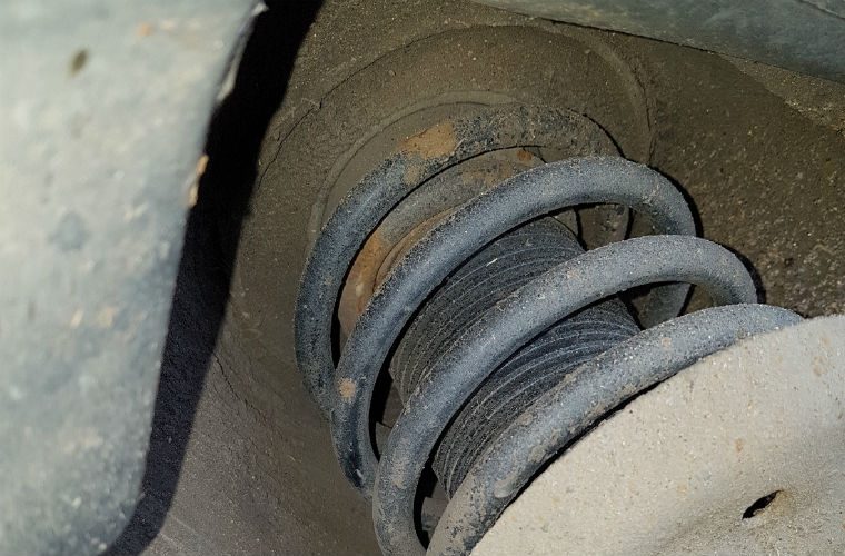
top of front strut, example
Now for some car content. After getting all the little things fixed on Nemo, I took him for a short test drive to see how he felt. He felt pretty good. Lots of boost, and plenty of power, but he made lots of noise. I could hear a clunk pretty much on every little bump. I figured it was the sway-bar bushings and replaced them: 13mm bolts hold the clamps on, and the bushing has a slit in it so you just need to remove the clamps, pull off the old bushing, slap on the new one and put the clamp back on. Times 2. The noise got a little better, but after pushing the fenders up and down, I believe the problem is in the strut-mount. From what I've read, after market struts that lower the front end (like Nemo has) put more pressure on the strut-mounts than the stock ones do, transferring some of the burden from the springs to the mounts to hold the front end up. This causes them to wear prematurely. So, I will be looking to replace those. Since I have a very healthy fear of strut springs, I will probably remove the struts and have new mounts installed by one of the shops around here. Better to pay with some hard earned cash than with some body damage.

A4 Rear Hum
Also on that test drive, I noticed that the rear end would make a humming noise once I got above about 30mph. I figured it was the wheel bearings, so I put the back end up on jackstands to confirm. The wheels had no play in them. None. Curious, I pulled it out of gear and spun the wheels, listening for noises (that would translate into a hum at speed). I heard clicking coming from the inner CV joints. So, that means at least removing one or both rear axles. Fun. Of course, with the AWD, I can't be 100% sure the bearings aren't bad. I may not have gotten the wheels spinning fast enough to make noise.

the diff oil fill, example
I intended to drain and fill the rear diff while the rear end was up in the air, but the fill plug is stripped. While I was under there, I got to see just how much caked on grease could remain attached to the outside of a differential without falling off. The answer: a LOT. I am really concerned about the health of this diff, and the whole rear-end, for that matter. Before I go any further with it, I will collect a second opinion. After that, I think it will have it's ass-end in the air for a while as I replace CV joints, and/or wheel bearings and fight off the fill plug so I can refresh the fluid. I'm not sure a 20+ year old 230k+ mile A4 is worth terribly much, but this is how we learn, and this could be a useful daily-driver for someone, maybe, eventually.

Well, that's it for today. I have not gotten back into the Zed paintwork since I put up the car ports. I really wanted to get Nemo road-able first. With the car ports up, I have more paint prep to do, and I need to figure out some sides for the car port space so I can heat and paint. Thanks, as always for following along-

Tuesday, August 25, 2020

Dust Dodging

If, after my last post, you guessed that I was going to find something to do other than sanding old paint off of Zed, you were right. I just can't get myself fired up to do that. I think I'll just have to put in an hour here and an hour there or it will never get done. Seriously, I thought after the rain we got recently I would get all fired up, but... nope.

Passenger Side
It started with something so simple. I was sitting on my front porch, surveying the herd while sipping a beer as the evening turned to twilight. Like a beacon, the white trash-bag taped over the front passenger window of the A4 shined in the dwindling light. Yeah, that just had to get fixed.

So, off to the junk yard we go. I hadn't been to the yard for a while; long before the CoViD-19 thing hit. The scene is a little different now. Of course, lots of folks have masks on, and there's the safe-distancing stuff on the floor near the check-in / check-out counter. But, more than that, it seemed like the folks pulling parts were pulling parts for other people more than for themselves. I say that from partially overhead passing conversations. Regardless, there's something about the junk yard that I really enjoy. Sure, the conditions need to be right. The car you're looking for has the parts you want, and they aren't trash. Ideally, it isn't super cold or wet. When you hit those conditions, it is downright fun to pull parts. Today was that kind of day. I found a black 1996 Audi A4 Quattro that hadn't been picked over too much. Most important, it still had the front passenger window.

Removing and Installing A4 Window
window in
For all of the usual over-engineering that German cars suffer, the front window on the A4 isn't one of them. This is actually a very simple operation. The inner door card needs to be removed. It is held on by 2 small screws (one front, one rear) at the top. Usually, there are a pair of screws inside the door grab, hidden under a pop-out panel. Since the card in the donor and in Nemo had both been removed previously, these screws were gone. Once the screws are out, the door card lifts straight up, and then pulls away. The door holds the card with a cable connected to the inner door opener. This removes fairly easily. I did not have to touch this for the window R&R. Once the card is far enough out of the way for you to put hands on the window tracks inside the door, you're ready. Force the window slightly lower, like 3 or 4 inches. The bottom of the window needs to pass the inner structures enough for you to see where the window attaches to the tracks. Depending on the year, the window is held on with either Phillips bolts or Torx. One last item worth mentioning: shop-vac all of the broken glass out of the door and the floor. The floor part is obvious, but if you don't vacuum the door, it will have a cheap rattle of the glass bits every time you open and close it. Spend the 20 minutes and vacuum. You won't regret it.

The window removes and installs from the outside. When removing, lift the rear out first, with the front corner trailing. The install is the opposite, lead with the front corner and settle into the window lift-clamps equally. As you tighten the clamps down, pull/push down on the window to make sure it stays fully seated. Once installed, I decided to remove the after-market tint. I regret not doing it when it was out. I had to clean the window a lot after that, starting with peanut butter and then window cleaner but it looks like a normal window now.

While I was at the yard, I grabbed the front side lights, since Nemo has been missing his since T bought the car. I found a pair of fog lights from a slightly later model that I took, thinking I'd slap them into either Nemo or K'Lack later. Last, I pulled the front grille because the one on Nemo was painted flat black by a prior owner. Since leaving the yard, I have thought about going back for the hood since it is in such nice shape and the hood of Nemo has no sheen on it. Both the no-sheen and the black grille can be seen in the picture below.

Removing and Installing A4 Front Marker Lights
front marker in
Again, I was surprised at the lack of German car-maker hassles when it came to removing and installing the front side marker lights. First, open the hood. Above each of the 2 lights there is a small round hole in the front steel top that runs directly under the hood at the front. Slide a basic slotted screwdriver into that hole and find the small plastic tab jutting rearward from the light fixture. Press down on the tab and with your free hand, pull the light forward. It pulls out about an inch and then needs to slide a little bit to the outside, and then pulls the rest of the way forward and free. This makes replacing that bulb super easy. In my case, it was a very simple case of installing matching front side-markers. Once wired up (socket clicks in and is held with 2 small plastic tabs), the install is the reverse. No, really, it is. Set the housing into the hole, slightly to the outside, but oriented as it will look when it is in it's final position. The tab that you pressed down on above needs to find it's way around a vertical plastic bit. Then, the housing sets deeper, sliding towards the inside. Set the pins into the alignment holes and set it all the way back. It should "click" to let you know that the tab has reset.

Just like that, the A4 looks way better. There are other things Nemo needs, like finding the oil leak and fixing the trunk (latch broken). But, the easy stuff is done, and now it is complete. So, in theory, I can leave it alone and shift focus onto Zed. But I think you and I both know that just isn't going to happen. I just don't want to.

That's it for today. Thanks, as always, for following along.