Showing posts with label panel. Show all posts

Tuesday, June 21, 2022

Interior Carded

Once the headbanger was installed, getting the interior to a usable state was a downhill run. This post is really more a collection of all the little things that got done so we could hit the road. So, for today, "complete" means "good enough for this Summer"; it does not mean we're done. I will be picking this up once camping season comes to an end in October. Before I begin, Hapy Summer Solstice.

Cab Floor Complete
I had left some of the MLV splits un-taped. So, I started with that. I discovered that the Jute and MLV was too wide between the outer edges of the seat rails and the doors to allow them to close easily, so I trimmed them down. Then, the edges were taped down.

Sun Visors
sun visors in
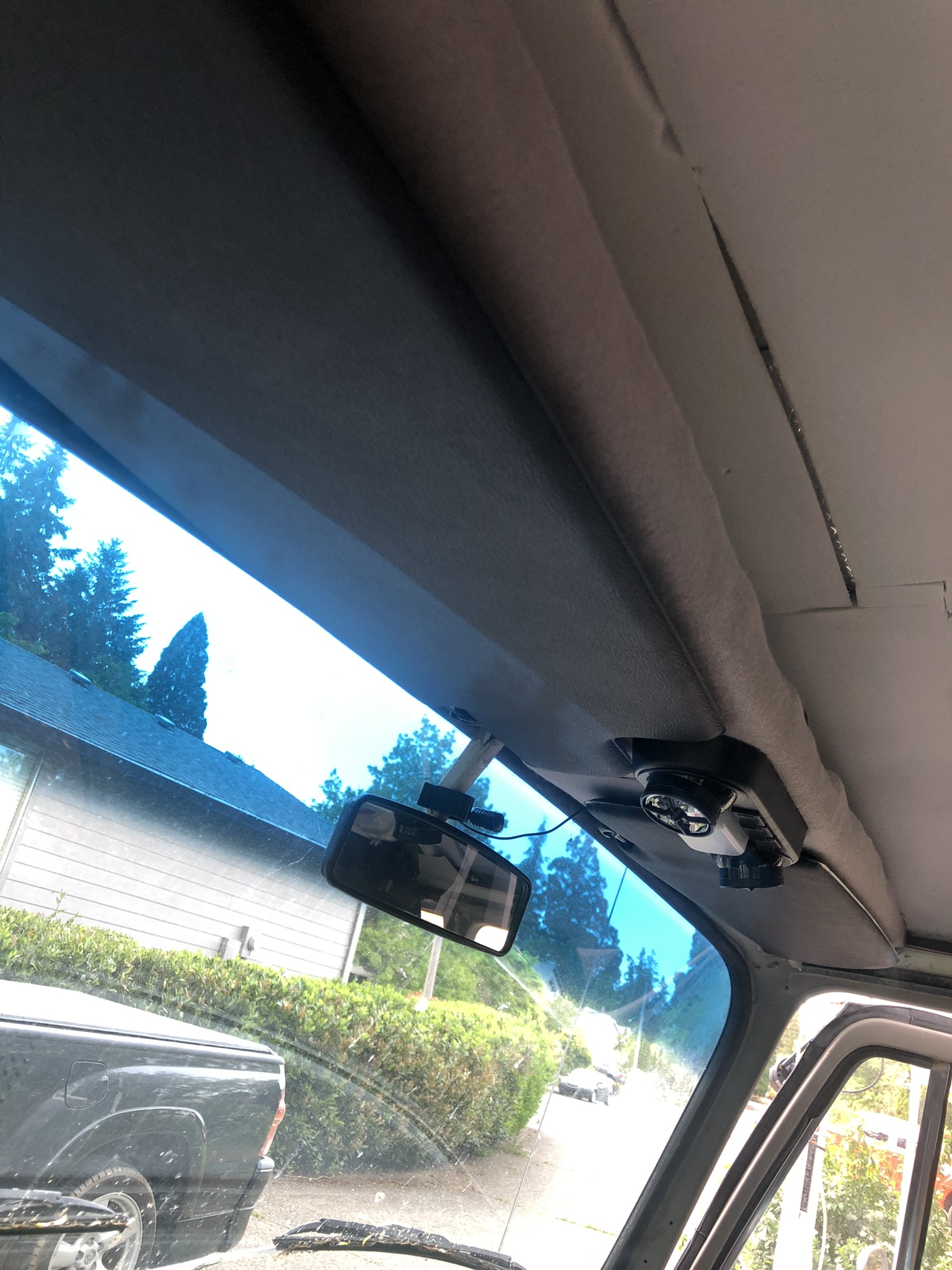
One of the upsides to the new shelf was the potential addition of sun-visors. The visors that are on the market these days are not the same as the ones I removed; that could be a reflection of my old visors, however. These new ones are shaped differently, with a pop-out on the end that is designed to go behind / around the mirror, and the little stick on the end that is supposed to go into the little keeper near the mirror is therefore much shorter. So, if I was looking for a direct-replacement, these would NOT have fit properly, but, again, it is entirely possible that the PO installed bug visors or something way back when. The mounting base near the A-pillar is the same. I re-tapped the holes, knowing at least one, if not all of them, had metal screws instead of bolts at one time before. I threaded M4 Phillips bolts in to hold the visors. I attached the little keeper thing to the underside of the shelf. So, the visor, when not in use, tucks flat to the underside of the shelf. It turned out that the weird shape of the visor allowed it to almost wrap around the light fixture, looking like it was designed for that install. Sometimes, its just better to be lucky than good.

Cab Door Cards
cab cards nearly complete
Recall, my old door cards were falling apart cardboard. There's a cat in Arizona named Werksberg who makes door cards out of PVC, and I ordered a set last Fall (his TheSamba ad). Apparently, his costs are skyrocketing so if you want some of these and have been sitting on the fence, you might get priced out if you don't make a decision soon. Anyway, I was finally ready to install the fronts. Unlike the original cards which need to be installed with metal clips into little rubber boots, these cards deliver with small plastic molly's which press through the card into the original holes. They appear re-usable. We'll see. The driver door card is not staying put, even after adding double-sided tape so I may need to add screws.

When I removed the original-to-me cards, I removed the little door vent things. I set them in my trove of parts and did not install them when I put on the cardboard cards. I put them on this time. The door looks much more finished now, as you can see in the picture above-right, here. The rest of the card install is the same as original. The window crank removes / installs with a Phillips screwdriver. As does the chrome door latch mechanism and the door pull strap. Once installed, the door looks so much better than it did. I have not decided if I will apply the thin closed cell foam or not, but I am not doing it for now.

Kicks
partitions and mid-walls carded
The last thing I got after in the cab was the re-install of the kick panels. With the new flooring and 4-1/2" speakers, this was not as simple as before. Still, I found by setting the outer edge and then bending the card, I could get it pretty much where I wanted it. I pulled the jute and MLV up, allowing the card to sit on the floor. I could remove them, and cut off the lower 1/2" so they sit on top instead. Meh. Something to think about as we drive around this summer.

Slider Door
Moving rearward, I pulled the middle row seat out and the original-to-me slider door card. The slider had not gotten much treatment over the years, so it got CLD and 2 layers of Mega Zorbe. I thought the extra layer might reduce the racket when the door opens. It didn't at first. I spent some time with oil & grease cleaner working on the door runners, and that actually helped a little bit. The lower door roller is the source of the lion's share of the noise and noticed that the outer edge of the runner was a simple 1/4" tall thin bit of steel. So, I ran some leftover white "U" seal I had from doing the luggage rack to see if that would help. Nope. It effectively pressed the wheel against the inner steel track edge, causing it to make a different, but equally unpleasant, noise. I concluded the wheel was the noise-creator, and I ordered a replacement lower guide with a vinyl wheel, instead of steel.
rear tail gate carded

There are 2 bolts and one Allen-screw holding the guide to the door. The bolts on the old guide were so rusted, they broke off, leaving me with just an Allen-bolt holding the guide in place. I will periodically shoot those rusted bolts with penetrant, and when I am able to remove them, I will use M6 bolts in their place. I will apply anti-seize, though. With the new lower guide in, the door was quieter, and operated more smoothly, but the upper guide was making noticeable noise now. So, I removed it, and improved it with penetrating oil until the guide-wheel would easily spin between my fingers. I re-installed it, and now the door was as quiet as a modern slider.

More Cards
I had some daylight remaining, so I grabbed the door card for the slider, and installed it. I also installed the card for the wall opposite the slider, and installed it. I did the rear tail gate and the extra cards for the rear-facing partitions behind the front seats. Each of these took some fiddling to get right, but that was on account of Hapy, not because of the cards. These things are great; the holes are mostly in the exactly right spots and the bag of Mollys had more than enough fasteners for me to damage a bunch of them and still not run out. I believe I can fit more sound deadener between the partition cards and the partition, and I may need some foam to reduce vibration noise, but right now, the interior of the bus looks really good. Removing those cards to add noise deadener will be simple when /if  I choose to do it.

I have a couple of cards remaining to be installed along the seat pedestals and I'll do them as the mood strikes / time permits. For those keeping track at home, I have installed the panels which sit at either end of the rock-n-roll bed, arching over the rear wheel wells, and have I attached the panels that cover the bare steel in the sleeping area. Because the sleeping area cards abut the rear-wheel cards, I needed to do them in the right order. As you can see in the image on the right, here, these cards, when used together, make a nearly seamless span. Boo and I will especially appreciate the sleeping area cards when we're camping. There are few things as jar-awake as having some bare skin touch up against the metal side after it has cooled down overnight. That is some quick-awakening. While this plastic / PVC will not be a great deal better, it does create a foundation for some foam and then some fabric later.

At this point, I felt ready for a test flight. I'll post on that next time. Thanks, as always, for following along-

Tuesday, March 2, 2021

MGB Interior Panels - Part 2

Today, I continue on Oliver's (the MGB) interior because the weather remained a preventative from getting to the cars outside. Darn, have to work in the semi-heated garage.

High-Level Door Card
black door now out of place
By now, the door cards were looking completely out of place, as the only remaining all-black panels. These are a little more complicated than the front kick and rear quarter panels. First, there is a top padded section which holds the top of the door card in place. The padded section is held on by 4 screws (2 each front and rear) and is wrapped with black vinyl. The interior kit delivers with a section of cream-colored vinyl to replace it. Additionally complicating things, there are the window crank, and the door latch pull and lock. In my case, I removed the armrests shortly after buying Oliver, but there is the old blown speaker. Last, each door card is held to the door with 13 plastic clips. Since these are original 1978 plastic, I suggest having replacements on hand. The interior kit did not include these, but they are, like $0.50 each or less online.
 
I didn't take a picture of the driver card before I started, so here's a picture of the passenger side, from the open driver door. I leave that towel on the driver seat so I don't accidentally get grease or anything on there while I work on him. You may also notice I have omitted the center console. I think the interior looks less complicated this way and the console acts like a little wall between the driver and passenger, which neither Boo nor I liked. Either way, there's no place to put a beverage. I may solve for that one day.
 
Padded Section Reuse
after polishing
I considered re-covering the padded section along the top, but after removing it (4 Phillips screws), I decided not to. First, the wood inside the padding is starting to fail (see picture below). It's not totally bad, but bad enough to warrant replacing eventually. I figured that if I used the cream on that now, I would not have it when I replaced the wood. Second, the black vinyl, while also not perfect, could get cleaned up with some leather cleaner. Last, I already had a cream and black contracting interior so retaining the black long the top would help underscore that. Ultimately, I believe retaining the black just for that contrast reason was plenty of justification. I think it looks really good.

So, I cleaned the rust off the chrome ends with some Goof-Off, and polished the vinyl with leather cleaner. The window felt was fairly worm out, so I removed it with a slotted screw-driver. Rather than use a staple gun to install the new one, I used 5/8 inch #18 brads. When installing these, you will notice that the chrome/felt does not go all the way from the front rubber seal (sealing the flip-out window) to the rear-most point on the window. I taped the felt to the padded section with painter tape and held the unit against the door, shifting the felt side to side until it was where I liked it. Then, I sent half a dozen brads in to hold it firm.
 
Removing Rusted On Window Crank
backside of padded section
As easy as it was to remove the padded section, removing the window crank was the opposite. The Phillips head screw had fully rusted to the mechanism. I applied Kroil and let it set, but it couldn't effectively penetrate past the window crank. I had to resort to my set of "easy out's". I find these are neither easy, nor do they really get the stuck bolt out (could be user-error), but in this case they did what I needed. After stepping up the drill bit size a few times, the head of the bolt fell off and the window crank handle could be removed. Once out of the way, I just needed to pull the plastic retainers from around the door handle and the door card came right off. I removed the remainder of the bolt from the window crank with a big set of lock-pliers. While I had the Kroil in-hand, I lubricated the various moving parts of the window: the window control joints and the spring. Surprisingly, this reduced some of the clank-clank-clank noise when the window is raised and lowered.
 
Outer Scraper
torn down
The last bit of demo was removing the old outer scraper. This is that supposed-to-be pliable rubber that presses against the outside of your window, stripping off water, mist or fog when you roll down the window. More importantly, it reduces rain water from running to trickling into your door. My scrapers were hard and chipped, so they needed replacing. They are held to the inside of the door with 7 rivets. I set a slotted screw-driver blade against the rivet and smacked the handle with a hammer. The rivets pop right off, but the bits fall inside your door. Once free, the new scraper lines right up with the original holes, though on the very end there are a few different mounting holes, probably for use on different models. I needed to open the holes a little bit with a rat-tail file in order for the new rivet to easily fit through.

To mount, I set all of the rivets through the scraper and loosely set them into the holes in the door. With my riveter, I started on the ends, working my way towards the center. With each rivet, I would make sure that the rubber set up on top of the door, and did not disappear underneath / inside. I found that I had to press the riveter and the scraper hard against the door when pulling the trigger. With the scraper riveted in place, I checked the window action.
 
Noise Muffler
window crank and spring
With the scraper in, I cleaned up the inside of the door first with the shop-vac and then with spray cleaner. With the door cavity relatively clean, I applied some noise deadener. I realize this is a convertible, so there will always be noise. The door application is really about making the door sound solid when it closes rather than tiny and clanky. It doesn't take much to make a difference. I have read that as little as 50% steel coverage is sufficient. I am not sure I even got that much covered, though the door has a satisfying, solid "chunk" when it closes now. I ran a 4-inch tall strip from the outer rear view mirror to the door handle above the belt line (inside the door cavity, of course, but against the outer skin). Below, there are 2 front-to-back channels to which I applied 1-inch strips from the window regulator to the rear edge of the window. Below the channels, I applied a rectangle along the lower rear section. I found that the spring clank-clank-clank could be felt most on the steel directly beneath it on the inner skin, so I put a 4-inch square inside the door cavity on that section of steel. All sections were pressed down with the little roller application tool for a solid bond.
 
Plastic Sheeting
Originally, these doors had a vapor barrier. This door, however, did not, except for the small sections around the door handle and window crank. So, I made one out of a kitchen garbage bag. If I had thicker-mil plastic, I would have used that, but these bags are hard to cut, so I don't expect this to fail. I cut the bag so I could completely cover the door, and taped it in place with painter tape. With a Sharpie, I marked where I wanted the vapor barrier and then cut along the line. Since my furnace is in my garage, my options for adhesive were limited. I would have used spray adhesive or the brush-able epoxy, but both need ventilation and are explosive hazards. So, instead, I used Elmers Wood Glue. Yes, that's right: wood glue. It took longer to dry, but it held the plastic firm during the panel install. While it dried, I cut holes for the door latch and the window crank. I have found that applying adhesive on vertical angles creates a path for water droplets to follow if/when it gets between the plastic and the steel. On other words, don't apply adhesive straight across: it will only trap moisture against the door.

Panel Install
home-made vapor barrier
I could feel the end approaching. With the holes cut in the sheet, it was time to prepare the panel with the 13 clips. The card has 13 very obvious spots for the clips. They are shaped like a classic 2-ball snowman: large circle on top of a smaller circle. The clip slips into the larger circle and is then pressed into the smaller one. I could have re-used some of the clips from the original door, but after over 40 years, I was not sure they would not break during install, or shortly thereafter. With the clips in, the hole for the window crank needs to be cut next. Similar to the rear-quarter panels, the door card shows exactly where the hole needs to be. Unlike the holes for the rear quarter panel, though, the window crank hole needs to be cut almost all the way out to the hard-board edged circle. Also, the leather/vinyl has a padded backing that needs to be cut through.

I decided to not include the arm rest / door pull and I am not putting speakers back into the doors so this one hole was the only one I needed to cut. This greatly simplifies the look of the door card (see picture below), and even with the extra bounce from the thicker card, I can pull the door firmly shut simply from pulling on the padded section. The card did arrive with indications for both the arm rest and the speaker mounting locations, though.

With the hole cut and the clips in, I was ready to press it in. I started by aligning the bottom clips with the holes along the bottom of the door. Then, I clicked in the clip nearest the rear view mirror and then worked my way around, snapping the card into place. I trimmed and cleaned up the hole for the window crank (I had cut too conservatively beforehand) and then installed the crank. I again tested the window action.

Padded Section Install
so pretty
Last, the padded top goes back on. The new cards are more stiff and thicker than the ones that were just removed. It will be some time before these new cards settle in, and the original screws for the padded section were not long enough to bridge the gap, initially. So, I found a screw in my drawers that matched the thickness of the original screws, but was about 3/4-inch long. I set it aside for a moment and attached the front-edge of the padded section with the original (smaller pair) screws. I left them plenty loose so I could adjust and then grabbed that long screw. I sent it through the lower of the 2 holes in the rear mount and tightened until I could send one of the original rear screws into the door and have it grab. I checked the alignment and then snugged that original bolt. I pulled the long screw and sent the other original rear screw in. Last, I tightened the front mount screws.

Feeling quite satisfied, I shut the door... and it bounced back open. Ah yes, the cards are thicker. I closed the door hard and it held. I figure it will take some time for the rubber in the weather-seal and the door card to come to terms with one another. To help speed that, I will leave the door shut tight. Of course, the not-dry-nor-warm weather outside will help that door stay shut for a while.

Well, that's it for today. I need to do the other door, of course, but with the passenger door so close to the shelves in the garage, it will wait. Until then, well, I'll have to find other things to fix on the fleet. Like the clutch on Gramps, the rear wheel bearings on Nemo or maybe something I haven't discovered yet. We will see. As always, thanks for following along-

******

surround bits
UPDATE: I did the passenger door this past weekend (5-June), following these instructions. I had 2 additional observations. First, the replacement inner door felt scraper is about 1/2" shorter than the original. The missing 1/2" on my original did not have any felt left, and it was the section closest to the door handle, up against the chrome end. Second, I omitted the last step in the instruction above regarding the 2-piece plastic rounded-cornered rectangle that goes around the inner door pull. These are thin, and could be damaged upon removal. Fortunately, my old vinyl cards were not holding on too tightly, and they removed with ease. The top part slid right off, simply by pulling up. Once removed, the bottom came out easily.

Installing the Plastic Inner Door Pull Surround
I found the install to be much more difficult. The new vinyl has much more grip than the old vinyl. Also, the card wants to be flat, so there is natural pressure away from the curvature of the door. The plastic bits had 4 little bumps (one on each short side and 2 along the longer side) that need to get under the door pull. After multiple failed attempts, I found success. Starting with the bottom piece, I got the plastic wet. I set the 2 short sides on either side, below the pull, and while pressing against the card with one hand, pressed upwards on the corresponding corner of the surround. I moved from side to side, moving it a little at a time until the bottom edge clicked in.

halfway there
The top piece was harder to manage, in part because my card has a piping strip that runs right along the spot where the plastic bit needs to sit in order to install it using the same method. So, again, I got it wet (reducing friction) and rather than start at the uppermost corner, I lowered the plastic piece so it was just below the piping, with the leading edges on either side of the surround. This placed pressure on the piece, and this is where an original piece could break. With one hand pushing the card against the door, I pressed the little bump under the inner door pull. This was a little scary, but once the second side snapped in, I followed a similar effort of sliding it down a little bit at a time on either side. Eventually, the top and bottom pieces meet, and the cards are complete.

Again, thanks for following along. I hope this last bit helps you out. I found following these instructions really helped me out when I went after the second door.
Tuesday, February 23, 2021

MGB Interior Panels - Part 1

I spent a great deal of time working on Zed's body. Before and after that, I spent even more time on Hapy, with the wiring (both the re-wire and the P0121 code), the furnace and the heater. Around those efforts, I picked up and improved upon T's old Audi, Nemo. Today, I took a break from those other cars to return to Oliver, the 1978 MGB, to complete some interior things I had left undone. I was going to get after Nemo's rear wheel bearings, but honestly, I just want something in the warm garage and Oliver is the only car in a garage, so... off we go into another multi-part post.

Where Were We
Recall that I blew some manna-from-heaven on an interior refresh for Oliver two years ago (See New Seat, What a Treat Parts 1, 2, 3 and headrests). I completely restored his seats, replacing all of the foam and the covers. Out with the old black vinyl and in with new cream with black piping leather. The lighter color is really nice when the sun is super intense, like in the early Summer here. I put in seat-heating elements, but haven't wired them in yet. Instead, I focused on summer-supporting stuff, like the new stereo. This new stereo included front speakers attached to contoured plastic boxes mounted to the outer footwell sidewall (See MGB Gets Sound, Version 2), but the kick panels were not there, so I started with those.

Kick Panels
creating kick-panel pattern
The kick panels compliment the seats in that they are the same cream color. When I ordered these, I appear to have selected the option to include map pockets, which I guess are okay, but with the little speaker boxes, will not be terribly useful. Anyway, in order to pierce the kick panels in the exact right spot so I can mount the speaker boxes, I pulled a paper shopping bag and some cardboard out of the recycling. I traced the kick panel onto the paper and cut out the pattern. I removed the speaker box from the driver-side sidewall, set the paper against in it's place and found the mounting holes with a small nail. I transferred the holes onto cardboard to test the location, and they were a little off. So, I pushed the nails around until they were in the holes well and tried again. They were still a little off, but the third time they were perfect. I transferred the holes onto the rear of the kick panel and drove the nails through from behind with a framing hammer. I set the soft cream material onto a shop towel and set that on top of an old kitchen cabinet door so the nail could pierce without damaging the panel.

speaker box
attached to p-side panel
After presenting the speaker box to the panel, and pressing the mounting screws into their respective holes, I drove the screws into the panel and then held the pair against the side of the car. I needed to position the panel around things, so this actually happened more along the lines of... in, then out, then in then out a few times until the panel was tight against the leading edge of the door weather stripping, the holes were aligned and the screws were lightly threaded in. I verified the routing of the speaker wire and then set the screws all the way in into the speaker box was snug, but not overly compressing the panel. I re-mounted the speaker and turned to the passenger side. I followed was the same process, down to the multiple sheets of cardboard. Since there are fewer obstacles on the passenger side, it was easier, but only barely because I did the whole thing leaning across the transmission tunnel from the driver seat. I could still feel my ribs 2 days later, but they really look good. Pain is temporary; beautiful clean kick panels... well, they're kind of temporary too. Just not quite as temporary, I hope.

Rear Quarters
With the kick panels in, the door panels look that much more black. And wrong. So, I really needed to keep going, but I thought I would do the doors themselves last. There are 2 triangular-ish panels that sit just aft of the seats with the rear-most edge following the contour of the front of the rear tire well. So, I call these quarter panels; I'm sure they have another name, though. I thought they would be easier than the door cards, and with the location of the car so close to the wall on the passenger side, I'm not sure how I will get to the passenger door anyway.

ideal top orientation
to hit all 3 bolt heads
These need to fit under the convertible top mounts, but otherwise their positioning is fairly straightforward. The 3 bolt/screws are partially obstructed by the convertible top frame. So you cannot just lower the convertible top to remove the 3 bolts that hold the mount to the car. You can remove one, but to get to the other 2, the top needs to be partly open. This is where an extra hand is very helpful. I didn't have one, so I tried doing just the driver side first. I started by opening the top so it was sticking almost straight up. This exposed or unobstructed all 3 bolt heads.

When I removed the the rear-most bolt/screw on the driver side, the capture-nut inside the B-pillar fell off (30 year old weld failed). Also, one of the hinge-points on the passenger-side of my convertible top frame separated. The capture nut is easy: they are sold on Moss for around $18US. For the hinge-split, I literally held the pin where it was supposed to go and forced the pieces back together with channel-lock pliers. I looked around for repair kits or something, but I was unable to find anything. At this point, though, it is working.

To get a sense of the work, I did complete both sides (using only 2 screws/bolts on the driver side), one at a time, leaving the other side firmly attached. With the convertible top frame up, just like it is pictured above, remove the 3 bolts/screws. I completely removed one, and then moved back and forth on the other two, slowly removing them. With the frame lightly held in place, I shifted focus onto the panels.
 
The Doing
I tried 2 different approaches, and found the second approach works better. First, I tried to poke a tiny hole in the panel for each of the 3 bolts to pass through and then widened the hole with something so the screw/bolt can thread in without catching vinyl/leather on its way. Take care not to make it so large, however, that it is larger than the frame hole supports. On the passenger side, I used a razor knife to cut a small "X" for each of the 3 holes. Either way, set the panel nearby, and get yourself seated on the parcel shelf at the rear of the passenger area.

I completed the removing of the 2 final bolts while holding the frame steady with my head. Yeah, that's right. This is where having a helper would be very helpful. With the frame held steady (either with your head or by a helper), lift the mount up just enough to get the card in place. I set the rear-most corner in first, and then flexed the card to press the leading edge behind the weatherstripping. The holes for the frame will line right up, but I checked with a bolt to make sure first. Then, I lowered the frame down into place (optional tonneau cover mount held firmly against the top frame), and sent a bolt through, threading into the nut. With one fingered in, I sent the other two in, and then moved from bolt to bolt until they were all snug.

At this point, I have both of the front panels and both of the rear panels in. The doors are a little more complicated since the glass-scrapers need to be replaced, and the old cards are still in. Since the weather around here has been below freezing and wet (ice, freezing rain, sleet and snow), I will be continuing to play with Oliver since he is in the semi-heated garage until the weather changes.This means that my next post will probably include some work on the driver-side door card. The passenger side is trapped against a shelving unit, so I probably will not be getting to it for a while.
 
As always, thanks for following along-

Tuesday, February 9, 2021

Hapy Daily Driving

Well, that title might be overstating it a little bit. To clarify: Hapy is now capable of driving on a moment's notice. With the CoViD safer-at-home, I haven't been going anywhere. I may not have had an operable car for most of the last couple of months, but the lockdown has meant I haven't really needed one either. Today, I'll cover the little things that needed to be buttoned up after the big re-wire.

Reverse Lights
I mentioned the reverse lights at the end of the Electrical Gremlins saga. I had it wired up to a somewhat mystery switched 12V source before. When I tore the old wiring rats nest apart, it was left out of the new wiring. This resolution was fairly easy. Back when I set the mystery wire-up aside, I left the plastic-snap-shut fused wire in tact. So, there was just a plain bare wire to deal with. I fished it up into the spare tire well / wiring compartment from the engine bay. I spliced the wire into the switched source splice coming from relay 109 so the reverse lights will only come on when the computer thinks we are in "RUN". Since it already had an integrated fuse, this was a simple splice effort.

Headlight Flasher
When I was chasing the cause for my lack of amps during P0121 testing, I tore into the dash. I thought I had bumped something loose, and there are a bunch of things in there that could have shaken apart. Well, I didn't bump anything loose causing that issue, but I did bump something during that exploratory. Haha. During the Summer of 2020, I finally got my high-beam / low-beam flasher relay to work. It was because the replacement relay requires a source of 12V to pin 30. This pin wasn't on the old relay, and there is no wire leading to that pin in the original fuse box. I solved that before, but when I was looking for the buzzing noise during the P0121 effort, I pulled that relay and the wire heading to that pin fell out of the fuse box. I didn't notice that then. During post-testing, I discovered that the flasher no longer flashed. I found the wire, re-oriented it so it would not fall out, and returned things back to their prior cleaned-up state (zip-tied fuse-box). Hi-beam flash/relay works.

Defroster
Also in the Summer of 2020, I installed a defroster. Sort of. The defroster solution was moving the Vanagon rear heater under the belly, routing coolant along the driver side main beam and plumbing into the old air channel from just behind the front crossbeam. The air source was an experiment pulling from the old rear floor vent. The mechanical connection of the hoses to the heater was poor, and the experiment fell apart. This source needed to be remedied. Also, the switch was not operating the fan settings correctly. This was caused by poor quality wire connectors, so once the 3 at the switch and the 2 near the heater were replaced, we have a 3 speed fan again.

I decided that rather than solve for a cabin-source of air for the defroster, I would just remove the experiment for now. I have an idea for a source, but other cars need my focus. So, I removed the air supply hoses and called it good enough for now.

Mop Up
During all of the wiring work, the inside of the bus became considerably disheveled. It was one part shed, one part tool box and no part looking like a vehicle. This was easy to resolve, but made a huge difference in declaring the end of the work. The lot couch is back installed as a middle-row bench seat, for example. The rear speakers are hooked up and placed for sound again. After a quick trip with the shop-vac to get the wire-strippings and other fallout from all the work vacuumed up, he looked nearly ready.

I ran a test of the furnace, confirming that it would run on either the accessory battery or the main. It will, but the current draw for the glow-plug is so significant that I'm not sure I will want to start that heater if I am not running at least a float charger to the sourcing battery. Still, it moved the internal temperature of the bus from 43*F to 68*F (6*C to 20*C) in about 15 minutes. For the fuel-minded, it took about 500ml (or ~0.13US gallons or about 2 cups). As I understand it, maintaining the temperature requires far less fuel, so the consumption at that point dropped way off. I left it running for about an hour and the total consumed ml was about 530ml or 30ml (1/8 cup) for the remaining 45 minutes of keeping the bus warm.

I took one last step: I installed plastic kick panels I ordered like a year ago against the rear of the nose of the bus. Just like that, the cab looks like it is not an active project. It looks fairly clean now, actually. They install and remove easily, and once snapped in they really do not appear to need much more to hold them in place. The guy who makes them suggests poking holes through and screwing them into your bus. I might use Velcro, but I'll withhold decision-making until after we have had a few drives to see if they rattle or not.

Getting Legal
This last thing was actually one of the first things I did for Hapy after I set Zed aside. In fact, I think it was the registration that got me thinking about Hapy in the first place. His registration came due, and because of CoViD-19, I had to do it remotely. Since he is too old for smog and Oregon does not have inspections, I have been renewing his registration online for a few years. Still, this time I did the online steps in October 2020, but did not receive the stickers for his tag until January 2021. This used to take a couple of weeks at most. It sure felt good getting those stickers on his plates, though.

Test Drive
With the tags updated, the wiring fresh, the defroster responding, furnace functioning, etc... Hapy appeared nearly ready to be pressed into service. We just needed a test drive. For that, I did my usual neighborhood lap through a series of side streets out to the main drag, a quick 1-mile straight shot on that major street and then turning back into the side streets for home. As expected, Hapy was fairly peppy and responsive. He sounds great, and did not suffer any P0121 issues. There were a few stutters, but no codes, so I chalked that up to old diesel. That will solve with some snake oil and a fill-up. Considering that Hapy had not left the driveway in over a year, this drive was significant, albeit short.

Alt-Light
The battery light came on when the engine was revving low during the test drive, leading me to think that the unsettling "pop" noise I heard when the wiring was wrong (See Chasing the Hapy Electrical Gremlins - Part 6) was the sound of my alternator frying. This light had been popping on during testing, so the fact that it returned during the road-test honestly just reminded me. Before I jumped into anything, I in-bus tested the alternator: I alligator-clipped a fused wire to the alternator output and ran that wire on the ground up to the cab. There, I electrical-taped the bare wire to the positive probe of my multi-meter to free a hand. I set the negative probe into a small bolt-hole in the driver door frame for a good ground. First, a good base reading: 13.5V. Cool. I started the engine and it dropped down to 12.4V. Solid. With my hand on the go pedal, I revved the engine and watched the voltage climb up and down peaking above 14V. So, the alternator is fine. Since I have been running without an ALT/GEN light for 10 years, I could just ignore that light... Nah, I just can't do that. I figured that the bulb must simply be connected to the wrong wire of the 2 in the ALT plug.

I had spliced into the wire heading to the computer (DFM - or Digital Field Monitoring), and it needs to hit the one that routes to the cluster (L - Lamp). Simple fix: I cut the splice from the donor main harness to the 6-wire cable, and tied it into the other wire from the plug just upstream from the 4-pin plug. While I was back there, I added ring terminals to the sensor wires for the oil pressure and oil idiot light. There remains some wiring tidying I need to do on the driver's side, so I'll cut out the rest of the DFM-sourcing wire when I'm in there. 

As much as I'd like to say that once I completed, I took another test drive... I can't. I did test start and engine-rev in-place, however, just to see that ALT light wink out (which it did). Why did I not drive him? Well, remember Gramps (1996 VW Jetta 2-dot-slow from my folks that we gave to K2)? He re-appeared with a failed throw-out bearing after the first test drive, but before I'd solved the ALT light. So, I will have to juggle the herd to get Hapy free for a drive. And, you can probably guess what I'll be working on next.

That's it for today. While I may not need to go out much due to CoViD restrictions, I now have my beloved turbo-diesel powered microbus available-ish for whenever the need arises. While there are lots of little things I could tweak on Hapy, none of those things would prevent me from taking a drive. Sweet, sweet success. Thanks, as always, for following along.

Tuesday, September 8, 2020

A4-ward Progress

Apologies for the late publish. Not sure what happened; I'll chalk it up to user error. Anyway, a few weeks ago, I mentioned that in a charitable move, I bought Nemo (the 1997 A4 1.8Turbo) from T (See If You Love...). Today, I go through the fixes I have done to get Nemo ready for someone to proudly drive, while avoiding work on Zed, the 280ZX. In an earlier post (See Dust Dodging), I mentioned the replacement of the window and the front side marker. I did a few less obvious things that I'll cover today. Before I begin, Hapy belated Labor Day to my US readers. Traditionally, this is the start of the most productive period in our calendar year: from Labor Day to Thanksgiving. So, if you feel like you're working a ton over the next couple of months, it's probably because you are.

Oil Leaks
Old Volksies like to mark their spot with a little oil. Old buses and bugs do it. Now that Jettas and Passats have been around long enough, they do it too. It seems that VW's German brethren, Audi's, mark their spot as well. For Nemo, there are a few sources. I focused first on the leaking motor oil. I slid under the front end, and after having sat for a few days, the oil that had been flung up from below during a drive had dripped away, leaving fresh oil only where it was actually leaking out. There was a nice big droplet at the oil drain, so I checked the torque on that bolt. It was a little loose. Next, I could see fresh drops on the cross member under the oil filter. It was hand-loose. As in, I was able to twist it tighter with 2 fingers. I think we found our main culprit. With oil filter pliers, I tightened the filter snug.

The power steering rack has a leak, and before I do another steering rack removal and re-install, I am trying the Lucas Power Steering Stop Leak first. This has been leaking since T bought Nemo, and T had been managing the level regularly with just topping it off with regular fluid. I intend to eliminate the leak. The steering is still really good and tight, though I expect the upgraded suspension helps with the road grip and cornering on rails. I looked back through my blog and I can't believe that I never posted on the steering rack remove/replacement I did on Flash, maybe 4 years ago. I think my dislike of the banjo may have started with those banjo bolts. It was a really tough job, so I'm all the more puzzled that I didn't post on it. Weird.

Dented Front Fender
With increased confidence from my efforts on Zed, I wanted to tackle the dent in the passenger fender. I pulled the front side marker, following the process I described in Dust Dodging. Through the hole presented when the light was removed, I fed a pry-bar. I did NOT leverage against anything, I just pushed/pulled outward and the dent popped out. My efforts left a small convex ding, but it is much better than the cereal-bowl sized dent that was there.

Under-Dash Panel
this is from an auto-trans, but similar
With the outside looking fairly good, but needing a wash, I started looking at the interior. There are a few things that need improvement, but I'll really only get after a subset. I started with the under-dash panel. T had removed this panel to replace the clutch master cylinder and had not re-installed it yet. We had the panel, but lost the fasteners. I made-do with things I found in the garage. During the install, I discovered that the remote trunk opener button was faulty, so I will need to replace that. Otherwise, the install was about what you would expect. The panel should be held on with 3 bolts, 2 through the front and one from the side, near the fusebox. Threading the bolts from the front is a great opportunity to practice patience. Gravity is working against you, and you can't see where the bolt needs to go once the panel is in place, so breathe deep and expect it to take many attempts. Once bolted into place, these panels are supposed to have 2 pop-in covers which fit over the bolt holes. I only found one so I'll add one of those covers to the junk-yard list.

Passenger Sunshade
The last thing I got after in this car-fix session was the passenger-side sun-shade. This was sitting on the floor since T bought Nemo. It looks fairly simple to mount. The plastic hook-looking thing goes in with the hook facing towards the rear, and you press up and back until it rotates flat, leaving the mounting hole near the hole in the steel above. At least, that's the theory. The prior owner had replaced the headliner and when he did, he mis-routed the wire for the light on the mirror. Instead of routing the wire through the hole in the steel where the mirror "hook" goes, it was left just dangling below that steel. So, the options were: don't hook up the wires to run the lights, return the route of the wires so it passes it through the steel from above -or- hack something. I didn't want to not hook up the light. I tried to figure out how to re-run the wires, but it appeared to require removing a considerable section of headliner because of the shape of the steel ceiling, so that left me with some kind of hack.

I took my hacksaw (aptly named) to the sunshade housing that, when installed, disappears into the ceiling. I cut a channel for the wire to slide down, reducing the mount of wire that would be pressed between the plastic and the steel ceiling. This actually worked, and I apologize for not taking a picture. Hopefully, you can see the shape of the mount from the picture on the right, here. With the wire pushed into the channel, I plugged the wire into the plug hanging from the hole in the ceiling. I pushed the rest of the wire into the headliner, and then followed the "theory" I described above. It pressed into place with not nearly as much effort as I expected. Once rotated around, I threaded a bolt through, and the sunshade is not in-place and operable.

The other bits of the interior that need to be resolved include fixing the cover on the driver seat cushion, and replacing some of the brittle plastic bits. I may not get to those items, but I think I will try to get the AC working; it probably just needs a charge. The next most important thing to resolve is the trunk is stuck closed. I'll get after that the next time I choose to focus on Nemo.

Thanks, as always, for following along.

Tuesday, June 9, 2020

Hapy Gets Solar

Last summer at the Newberry Event, I met a couple who were driving a pickup with a camper set up down the way from me. We got to talking about this and that as happens at music festivals. Conversation turned to camp set-ups and after a walk-thru of Hapy, they showed me their camper. I had seen newer camper-styles before, but I was really taken by their tiny solar panel. Today's post covers my transition from covet to install for Hapy.
Zamp Solar
I'll start with the panel that the Newberry Event couple had. It was a small, like, 1 foot square, portable panel (like this one - USP1005). It had an extending foot so you could prop it up independently, and had all of the conversion electronics attached to it. All you needed to do was run the supplied cable to your battery and clip it to the posts. Shazam, you have a trickle charge running to your battery. This all seemed to good to be true, so I took pictures of it to research later. They explained that they only camp in central Oregon, where the sun is seemingly ever-present, so a smaller panel completely suits their needs. I figured that we camp on the fog-socked Oregon coast as well as central Oregon, the Willamette Valley, etc so maybe we could use a larger one.

solar port
I did some research. I found that Zamp Solar is a small company based in Bend, Oregon. The reviews were great, and everything is manufactured here, so a purchase from them directly benefits the central Oregon economy. So, once my annual bonus arrived, I bought us one with the 1/3 I set aside for "fun" stuff. For the curious, the other 2/3 are split across saving for the future and paying off the past. It is a model I learned from some money-manager types 20 years ago. The thinking is that you're going to spend a little on stupid stuff anyway, so budget for it with 1/3 of your win-fall so you don't blow it all. It also creates some savings and eliminates some debt. Anyway, so I bought a larger one (USP1002). I also got an extension cable and a solar port. I probably could have gotten the wire harness, but I didn't realize they had it until after I had ordered a different install cable.

Install
controller
Like I said above, adding a solar panel to your luxury (or main) battery doesn't need to be complicated. I could just set up the panel and run the cable in through the slider, under the rock-n-roll bed to the battery. In all honesty, if I need to top-off the main battery, I will run a cable through the open engine hatch and alligator-clip to the posts. Since 99% of the battery usage when we are parked is consuming from the luxury battery, I wanted something a little cleaner.

To start, I soldered a 10 gauge red-black cable to the solar port (red to red, black to black, of course) and then heat-shrinked the connections. Now that I had a plug with 20' of cable attached, I could consider where to install it. I had thought about a few locations: inside the rear driver tire well, and under the belly pan on the passenger side. I resolved to putting it just behind the driver in the driver-side pan. I figured that if we were going to camp in a sunny spot, we will park so that the slider is on the shady side, so a port on the (non-slider) driver side made the most sense.

The backside of the solar port is rather thick, requiring a hole saw. Once bored, I threaded the bare-wire end of the cable up through the hole. I have an old hole in the floor of the bus where the '79 kitchen used to be so I pulled it the cable through by putting my arm into that hole. I ran the wire up out of that hole (I'll repair the larger hole one day) and then along the bottom of the old fridge cabinet where the furnace (see the Parking Heater series 1, 2, 3, 4 and 5) now lives.

From the front outer edge, the cable bends around and inside that cabinet, and then runs along the outer edge before turning towards the center of the bus at the rear, exiting where the power wire for the heater exits. The cable runs the same path around the rear edge of the base of the rock-n-roll bed to the luxury battery. At this point, I added a ring terminal on each cable.

With the wiring route defined, I returned to the belly pan. I pressed the solar port into the hole, and drilled a pilot hole for a metal screw. I oriented the port so the cap ran fore to aft with the little hinge facing the front of the bus. This seemed the best for debris flying around under there while driving. Once that first hole was screwed in, the solar port was fixed, so I could easily pop the other 3 holes and thread in corresponding screws.

Testing
DrivewayFest 2020
The ring terminals slid easily onto the luxury battery extra posts. I nutted them down, and then pulled out the solar panel. It ships with a thick semi-stiff zippered case to keep the glass safe. It unzips easily, and removes by the pull of the handle. The panel folds in half, held with a simple twist clasp. Once released, the hinges are stiff, so it doesn't flop open. Instead, you need to choose to open it. Inside are all of the controls, the 15' of cable and the flip-down feet. I set the panel in a sunny spot, and the controller started flashing me status that was basically: no battery connected, but able to charge. I connected the extension cable to the attached 15' and then connected the other end to the solar port. These cable only mate one way, so this is super simple. I walked around to the panel, and toggled through the controller screen. According to the panel, I was getting 13.6V, pushing amps (peaked just below 5A, just under 2A when cloudy), and charging the battery. I felt the wires inside the bus to make sure there was no temperature at all (I used the same gauge wire so there shouldn't have been) and there wasn't.

We set up the bus for what Boo and I referred to as DrivewayFest 2020, and left the panel running all weekend. We rolled music and spent the better part of 2 days lounging by the bus. With the solar panel installed and the furnace finished, we are now 100% ready for 4Peaks.... 2021.

Since that first test, I have set up the solar panel pretty much any time I'm in the driveway working on the cars or the yard, powering the stereo so we have tunes for the work. The battery charges up quickly and then the panel suspends pushing amps until it registers a need. This panel requires no input from me once it is set up. Perfect. I'd rather use my brain effort on other things. I highly recommend Zamp Solar; I do not get anything from that endorsement. I just like them.

Thanks as always, for following along.

Tuesday, January 9, 2018

Capturing an Escaped Captive... Nut

Rain. and cold. and blustery wind. All of my projects except one are sitting in the driveway under tarps held down with whatever I could get my hands on. My new-ish job has a policy about how much paid-time-off you can carry forward into the next year, so I find myself with days at home. So... what to do? Work on the one project that's sitting in the garage so one day it too can sit in the driveway under a tarp while one of his brothers are in the garage getting worked on. Today covers one of the final steps to achieving that goal.

Captive Nut
test fitting a panel
On the convertible MG, the top fabric is attached to a steel frame. Depending upon the year, the frame could take on one of a few forms. Mine is the last style, which folds straight back with large scissor-style hinges. These hinges mount to the sides of the car just behind the door latch. The steel inner body panel has a flat surface into which 3 holes were drilled at the factory. Inside the panel a nut was welded behind each hole. These nuts are what holds the convertible frame to the car, and therefore hold the top onto the car. Yes, there are clasps along the top of the windscreen and there are little hold-downs along the rear deck, but most of the work is handled by these 6 bolt-nut combinations.

The Escape
With any car, rust and wear take a toll. On the MGB, the little captive nuts (1/4 - 28) can detach from the inner body panel. Once separated, the frame can be attached, but the person doing the attaching must hold the nut with a wrench or pliers or something. Since the entire inner steel skin is usually covered with a vinyl panel (on top of which the convertible frame is usually attached), the owner has a choice: no more panels, no more top or re-capture the nuts. The PO had decided to select multiple options: no more panels and no more top, leaving the frame stripped of canvas and disconnected, but sitting behind the seats after discarding the vinyl cards prior to selling it to me.

Alternatives
I've driven around in plenty of cars which didn't have all of their inner panels. The operation of the car is in no way negatively impacted. It just looks trash. So, I decided I would get the nuts re-captured. There are a few ways to go after it.

Go Crazy, Tear down and Weld - Since these were originally welded into place at the factory before the body was assembled, getting them welded back in the same way is virtually impossible. I imagine someone industrious enough could take enough of the car apart to get access to the nuts. I don't see the value. Maybe if you have dreams of showing your car at concours or something, this would be the most-like-original path. Or maybe you're just sadistic. Either way, rock on.

Ugliest welds ever
Get a Repair Panel - Moss has a repair kit (link here) that could be used to fix this, so clearly this happens often. They run $18 each, which isn't bad, but as I noted at the beginning, I have some time, and I don't want to wait for shipping. I imagine the kit is a pretty easy solution though: set it so it is aligned with the holes, mark the mounting spot with a pen, drill, install. Easy peasy.

Make your Own Panel - While not necessarily the easiest, if you have some time and either don't have the money for the Moss panel, or don't want to wait for it, it's not that hard. I chose this path and I detailed steps below.

Recapture
I have the nuts in hand and plenty of super-thin scrap steel lying around. I considered that the steel to which the nuts were attached did not need to be terribly stout. It just needed to be strong enough to hold the nuts in place against some modest pressure during installation. Once the bolts seat into the nuts, the plate doesn't contribute to holding the top on: its still the bolt-nut combination. With this in mind, I cut a couple (one per side) small pieces of HVAC sheet metal with tin shears to they fit in the hole, around the nut(s) which were still clinging to the inner body panel. I held them in place, marked the nut-holes with a pen and step-drilled holes large enough for the bolt to easily pass. I then sanded the steel to get any zinc coating off. This is important as the off-gassing from welding a zinc coating is really bad.

For some reason, my top had an extra bracket that looked like this, but not chromed. I think it is for a wind blocker (like this) that wasn't with the car when I bought it. Love that. Anyway, I took that bracket thing and used it to provide more meat for the next steps (see the top picture). I aligned the HVAC sheet with the holes in the bracket and then threaded the bolt through, tightening the nut against the HVAC sheet.  Next came some of the worst looking welds I have ever produced (see middle picture). That is saying something, because my welding skills are pretty bad. Still, I was able to get the nuts to hold to the sheet and hold well enough for me to remove and re-insert the bolts multiple times.
"Pop" goes the Rivet

Install
Whether you did the Moss repair panel or you made your own, the mounting to the car is very similar. The panel sits flush against the outer-side of the inner wall (inside the cavity) with the nuts pointing out (away from the cabin). With the Moss panel, you can hold the thing on from the inside and see where the hole will be because it's symmetrical. Must be nice. With the home-made job, its not. Instead, I made judgments based on where the holes in the body were, and where the panel was as I held it up against the wall from inside the cavity. I marked 2 holes on the inner wall, pulled the panel aside and step-drilled to 13/32". This is just a hair larger than 3/8" so a 3/8" pop rivet will fit snug without binding as it goes in. To make sure I got the holes in exactly the right spots on the panel, I bolted it into place and drilled through the holes I'd just made in the body and then through the panel. With the panel still bolted on, I pop-riveted the panels in. I was still able to easily remove the bolts from the nuts (without touching the nuts), so the convertible top frame should now be capable of being installed after the interior cards are in place.

That's it for today's post. Yes, I could have simply ordered panels and this would have taken far less time. Instead, I got to play with my MIG and save myself about $40US. Thanks, as always for following along, and I hope you're having a wonderful holiday season. Hapy NewYear!

Tuesday, April 1, 2014

Thinking while Dinking

I unexpectedly had Sunday available to putter on the bus.  Boo was supposed to work, but suddenly didn't have a shift.  So, after a visit to the gym (I really need to do that more), I opened the garage door, turned on some tunes and pondered the bus.  Sometimes, you need to just be with your project to have an epiphany.  I had a flash of brilliance that (hopefully) could solve the wet-weather challenges for good.

Cutting Cards
I decided that a free afternoon shouldn't count in my build versus buy math since the afternoon was free.  So, I pulled out the Dremel and cut another door card.  Okay, back up.  First, I took the first door card I did and started trying to hang it on the passenger door.  I found little things that needed to get adjusted.  The grab handle holes weren't big enough.  Then the inner latch surround thing didn't fit.  Last, I realized that the holes for the door clips weren't there.  That was kinda fun, actually.  I took the ratty old door card and laid it on top of the new one.  I set those on top of a fresh piece of MDF.  Once lined up, I grabbed my drill with a 3/8" bit and bored straight through the door clip holes in the ratty door card into the new one and the MDF underneath.  Perfect.  I pulled the ratty card off the stack and traced the other holes and around the edge.  30 minutes with the Dremel later, I had a duplicate of the new card.

I still need to do a little sanding around the edges to make it a really nice fit.  The holes line up well and the grab handle, window winder and inner latch all mount correctly now.  Its just a little 100%-ing around the edges.

Hanging the Plastic Curtain
Originally, the early VW's had a "vapor barrier" between the door card and the steel door.  This was because no matter how good your seals were, water would seep inside the door, and could slowly rot the MDF/cardboard cards.  Most VW's have had these plastic sheets ripped out by stereo installers or confused mechanics, and their door cards have accordingly suffered.  I have tried a few different things over the years to get a plastic sheet to stay in place, but spray adhesives, contact cement and gorilla glue don't work.  Or they work too well.  Ultimately, I've just driven around without door cards while waiting for the answer to appear.  I found a posting on a website where a guy used that blue poster tack stuff (called BlueTac), and said it worked great.  I'll be trying it myself: a thin line of that sticky stuff all along the edge, taking care to avoid the door card mounting holes.  It occurred to me that this might be the solution I've been looking for with the belly pan too.

The belly pan, if you don't remember, is really a mechanical protection against rocks and such.  I've been trying to also use it as a splash-guard to keep the pedal electronics dry.  I'm going to try using the BlueTac solution with a sheet of plastic.  Figure, if I can protect a door card, I should be able to protect the electronics the same way: simple sheet of plastic held in-place with BlueTac.  I should also be able to cover the uppers, making the small sub-floor water-safe.  Neat.

That's it for today.  I bought some 3M-verson of BlueTac at Office Depot yesterday so I'll try the plastic thing this week.  Until then, here's another picture from the door card development effort.
3/8" drill bit fits perfectly in the mounting holes

Wednesday, March 28, 2007

Head Banging without the Music

One of the unique characteristics of a 1972 VW Bus is how you get at the engine. For those used to leaning over the front fender of your favorite car, cold beverage in hand, while considering your timing, or the next oil change, or the Red Sox pitching staff, its a little different with an old bus. First off, the engine is in the back, which makes for some funny conversations at the annual smog check. It makes leaning on a fender impossible too, though the rounded corners are good for leaning :)

Once you're realized that the engine is back there, you discover that its behind a little door where the license plate sits. Pop that thing up, and you're in wonderland. Alice's wonderland, that is. For in the 1972 bus, that little door is the only way to get at your engine. I think of it as vehicular proctology. Between the coveralls, flashlight and tools, you can barely get in the door, much less do anything. Makes you wish for a little "eat me" cake, but that feeling only gets stronger when you realize you forgot a tool or need a sandwich and try to remove yourself from that doorway. *BANG* the back of your head hits the upper threshhold. That's why I always pop on a snow-hat before climbing into my engine door. I admit, its awfully hot doing that in the Summer, but its better than the inevitable headsmack. This one-door deal is really only a 1972 bus issue, as a top-hatch was added in 1973 and continued through the vanagon.

I'm tired of wearing a ski hat in the Summer. I want to be able to check something on my engine without getting down on all fours. I want to be able to lean against the engine opening and talk about the Red Sox pitching staff, and actually be able to see the engine when I'm doing it. So, what to do... why, cut a hole! Well, that sounds rash, but installing a door on the topside isn't such a bad idea. The question is how big a door? Would putting in a door compromise the structure of the bus or would additional bracing be necessary? Here are a few choices:

Baywindow bus hatch is 11" deep by 31 1/2" wide. Not too big, but engine access is achieved. Additional support or bracing is probably not needed, but I'd probably do something just to be sure. I don't think these are of much real use, though, because they're really quite small. With the coveralls and tools, can you really reach through an opening 11" deep and do anything other than utter muffled curses?

Vanagon Hatch. is 42 3/8" x 25 1/8". Huge. Makes one wonder "how much of your back would not be a door?" Well, I measured my back panel just for kicks and its 34" deep and 42" across to the westy closet. I'll remeasure tonight and repost if the numbers from memory are off. Its actually 44" across by 32" deep, but there's really only about 23", maybe a touch more, from the firewall to the rear door. Regardless, it tight. Additional supports or bracing would totally be necessary. A removable support in the center might be a good idea too. Big enough? Heck yeah. The lid would open like the hood on an old Monte Carlo. Of course, you'd breach the firewall with a hatch like that, at least according to my measurements, so this may not be such a good idea after all.

Type3/4 Hatch is 22" x 31" give or take a 1/4", with 34" on the diagonal from rounded corner to corner. Sounds about twice the size of the bus hatch, but not as big as the vanagon. It would barely fit, but bracing would be a good idea. Also, finding a lip might be a challenge, as the type3 and type4 cars are not as plentiful, and there are multiple layers of steel that would have to be cut through to get the original lip. Considering the closeness in size to the baywindow hatch (times 2) maybe 2 donor hatch frames could make a single lip. Sounds like it could be a lot of work.

make your own is always a choice, but rarely a good one. Lots of cutting, fabricating a door, maybe from the cut out steel doesn't sound like too great an idea. The edge of the cut out would need to be strengthened by something like a home-made lip. In the end, it won't look too good, probably won't be structurally sound, and will probably leak emissions into the bus. Bad idea.

Of the 3 decent ideas, I like the size and lineage of the type3/4 hatch, but the amount of work does give me pause. If I really need engine access from above, it will take more than cutting a hole and glueing in a vinyl window. Accordingly, I'll have to really plan this out before I do anything.

If you're thinking of putting in a hatch, I hope these dimensions were helpful to you. I collected them from different owners and part suppliers and should be pretty accurate. Thanks to the BusCo, theSamba and theDDB for helping collect the measurements.
