Showing posts with label glowplug. Show all posts

Wednesday, November 22, 2023

Hapy Update

Today I could continue the dissertation on the effort to move the furnace in our 1948 farmhouse. Instead, I actually have something car related... the check-in on Hapy that I said I was going to do in a prior post and then flat-forgot. Remember Hapy? He's the 1972 VW camperbus that launched this blog. I meant to post this yesterday, time got away from me.

Hapy No Start Returns
A few weeks ago, as the weather turned cold, Hapy became increasingly difficult to start. Again. I figured it was the same issue as last time (See Hapy No Start Again), and started checking things with my multi-meter. I started where the old problem was: the main fuse for the glow plugs. Nope, there's a clean over-12V signal there. Then, I checked the voltage at the relay, and it was fine there too. Same for the resistance in the wire and the fuse.. no issues. So, I started thinking about the glow plugs themselves. I swapped this set in when I put in the chipped CPU and bigger nozzles, but not because there was anything wrong with the ones that were in there. I had this set of plugs that I had lying around for a few years, and I was selling Flash. Flash had failing glow plugs (resistance tests between the plugs were not within a few ohms of each other). So, rather than put the new set into Flash, I got selfish and put Hapy's nothing-wrong-with-them plugs into Flash and installed the new-never-opened plugs into Hapy. Looking back, I don't think these plugs were nearly as good. I think we have had starting-while-cool problems from the beginning, but it was Summer when I did the swap and never thought about it. Until now.

I pulled the rear-most plug (#4?) and tested it by resting the glow plug threads against a grounded bit of steel on the engine and triggering the ignition to "run". After a 3 count, the tip of the plug started to glow orange. After another 3 count, I could hear the relay click off, and the tip returned to black. I did this a few times and each time it took a few seconds for the plug to respond and even then it was only the very tip. Based on some internet imagery, I concluded that those plugs were insufficient and bought a fresh set.

A few days prior to installing the new set, I started hitting the in-engine plugs with some Kroil penetrating oil at dinnertime. I did not want a plug to break off or damage the head during removal. Whether it was necessary or not, the plugs removed relatively easily. All of them had soot on them when they were removed. Into the trash they went. For each of the new ones, I applied some anti-seize onto the threads prior to installing and then only snugged them down (did not torque the snot out of them).

Unfortunately, my efforts to start Hapy when the glow plugs were not working did a number on the starter. Again. So, my attempt to start him after replacing the glow plugs was not fruitful. Since I did the glow plug swap around the furnace work, and the furnace still is not operational, I self-limited my time to just swapping the plugs and then getting back under the house. I returned the following weekend (bumming rides and car-sharing with Boo the week between) to remove and inspect the starter.

should be 1 part, not 2
I admit, I expected the starter to just need a remove / re-install cycle. I was wrong. This rebuilt starter was installed in June 2023. After a summer of being my "daily driver", the starter was cycled well less than 500 times. I guess rebuilt Bosch starters are not all the same. Maybe the starter was a Bosch but the rebuild was done with cheap-o parts, leaving just the case as a Bosch unit. Regardless, it did not take very long to notice that the seal on the end (which is supposed to go around the shaft which juts out when 12V is applied) wasn't there anymore. It had potato-chipped inside the little pocket where the nose of the starter goes. Neat! So, off to the internets I went looking for a suitable replacement. I decided to get a new one from MetalManParts. Run by MetalNerd, his site only sells things that he personally fabricated or installed into his own vehicle. I have purchased both types of things from him before and have no regrets. Since Bosch was sold off to Seg Automotive, he now supplies new starters from them. I trust that if he is selling them, he is using them.

Sadly, the install of a starter has become fairly rote, since I've done it so many times. I simply put a 19mm socket, 13mm socket, a ratchet and a couple extensions into my pocket, slide under the bus with the starter and it's installed in less than 15 minutes now. If the rear sway bar were not there, I could probably have it done half that time. Of course, I ran the battery down with all my glow plug testing, so it got a spell on the battery charger before I could test my handiwork. Once that was resolved, I turned the key to "run", counted to 6 (for the glow plugs, it's 45*F here) and returned the key to "off". I repeated and then tried to start. Fired right up! I let him run a few minutes to top off the battery and now he is back to being my daily driver.

Hapy Heat Not Heat
Remember all that effort I went through to install the Vanagon rear heater under the bus for some heat? While that was fun, the result is not much heat. I described the lack of warm on the drive to and from the Cascade Equinox festival. Beyond the lack of detectable warmth, opening the valve to try to get heat has resulted in a coolant leak. I can attribute no other source for why Hapy's coolant level is suddenly not holding. So, I turned the valve back off and will be replacing the Vanagon rear seat heater with something else: a Maradyne Fans Stoker heater.

Maradyne, but could be any
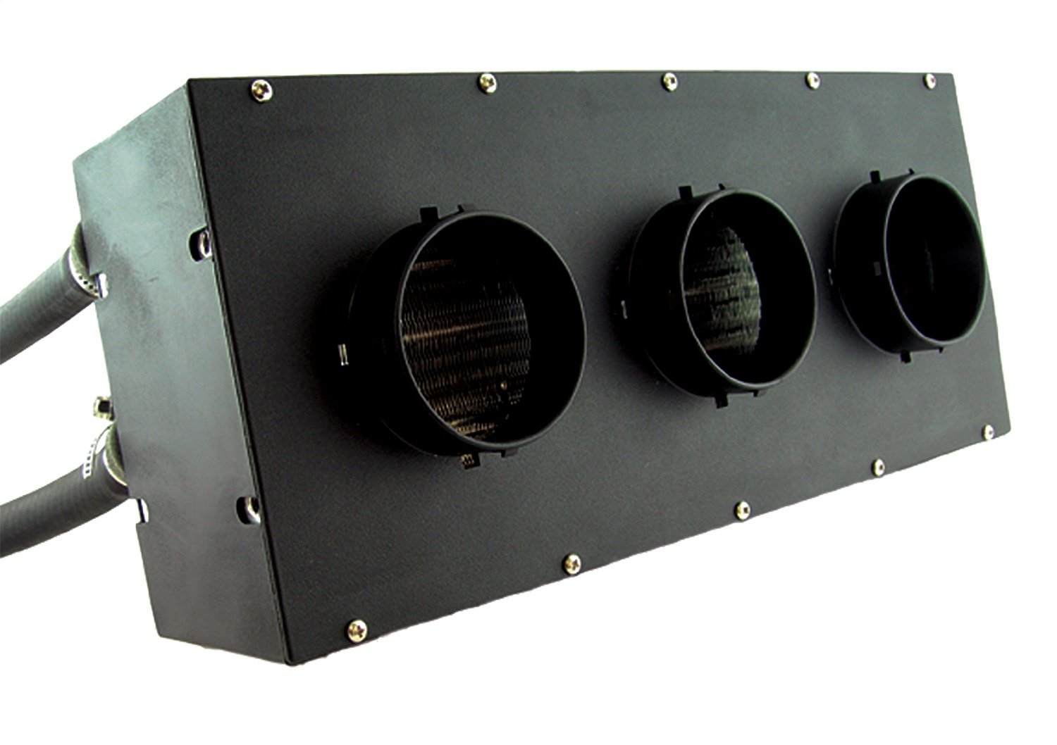
There are lots of auxiliary fans which all look the same and have the same spec's (300cfm, 40k BTU - airflow and heating capacity, respectively). JEGS has their own, for example, that looks identical. Since I am unsure who is the originator, I went with a manufacturer with a known, solid reputation. There is little documentation and hardly any photos of this particular unit on the interwebs, making this choice perhaps a little more risky. I find the 40k BTU number everyone is using to be gross hyperbole, but I don't know how to test that nor the 300cfm number. I will bench test to get some amp-draw numbers before I install it. The amp-draw might be useful information for the next person since even Maradyne doesn't list this detail on their product page. And, it could be one more thing that is exactly the same on all of these units. For future reference, the JEGS unit draws 5.5, 7.1 and 11.6 amps (for low, medium and high settings respectively). I had relays in-place for the medium and high draw switch positions for the Vanagon unit. I don't know if I  will re-use them. Perhaps the amp-draw numbers will help me decide.

One other thing to point out: none of these heaters ship with a coolant control valve. Since I was leveraging the valve in the Vanagon, I have to add one of these or the heat will be on maximum all the time. I included this "vintage" control valve in my order. I thought about going with an electric one, but decided that I would really like to re-use one of the big original heat-sliders on the dash to control the amount of coolant flowing into the heater core. That feels more authentic than another knob attached to the bottom of the dash. Of course, I haven't ever had that control cable, so I will be running this either full-on or full-off until I do.

For now, this means that trips in Hapy will be just like all the other trips I've ever made with him in the not-Summer. They will be cold. It will be like driving around in an ice-fishing shed, unless I can either install that heater soon-ish -OR- get the little Chinese diesel heater/furnace working.... or both. Since I do not have a garage and I barely have a 4-meter square piece of concrete to work on... and I have a house furnace to fix, I do not think Hapy's heat will get addressed terribly soon. At least I have the parts for when I do. Of course, now that he is my daily-driver again, I may decide another week without a furnace might be a fair trade for some heat, any heat, in Hapy.

That's it for today. Thanks, as always, for following along-

Tuesday, July 4, 2023

Hapy No-Start Again

Sadness arrived again just prior to Summer Solstice: Hapy refused to start. Today's post covers the initial issue, it's resolution and the subsequent issue that arose along the way. Finally a car post! Before I begin, for my US readers, Hapy Independence Day.

Glow-Plug Not Glowing
I jumped into the driver seat to get to an appointment on a relatively cool weekday morning. By relatively cool, I mean 55*F (13*C) or so. Hapy didn't want to start, and he was throwing a code. I checked and it was the glow-plug P0380 error. Joy. Hapy had been harder to start in the mornings on cooler days, and I probably could have put one and one together, but my brain is pretty full these days. Anyway, that evening after work, I shifted into diagnosis mode. It being so close to the solstice, we have workable daylight until 830PM or so. I started with checking the resistance for the 4 plugs. I feel like I replaced these when I did the new injectors, and when I tested them (lowest resistance setting on your multi-meter, you want them within like .6 of each other)... they all came up with the exact same resistance (.8). So, not a glow-plug problem. Before tearing into the harness that Justin and I installed, I thought I would check the relay and the fuse.  

First, I pulled the relay and checked the voltage at the relay: almost 0V. I concluded it was not the relay. Recall that I just redid all the wiring a couple of years ago, so I pulled out the notebook diagramming the circuits, and found the right battery-top fuse. It's the same as the one any other TDI of this vintage uses: #2. Knowing the wire was fresh, I figured it was probably not the wire. Still, it was wise to check the connectivity of the wire: almost 0 resistance, so the wire is good. I moved on to the fuse.

original adapter
On the supply-side of the fuse, I had 12.45V. Hmm... even after all those start attempts, and there were many, I still had lots of juice. On the other side of the fuse, however, I had almost 0V. Not 0, just a shade above 0. So, the fuse wasn't blown, it was just acting like a big-ol resistor. So, I removed the nuts (10mm) and pulled the fuse. Sure enough, there was almost infinite resistance. These fuses are basically a metal bar (see picture above), but because they are exposed to the elements, they can become compromised by the weather. I do not have a replacement, so I cleaned it up with a metal file. I would grind away on the crud a bit, check resistance and repeat. Once I was able to consistently get nearly 0 resistance through the fuse no matter where I set the probes, I re-installed it. The referenced image on the top-right, shows both the result of some filing (on the ends) and the built-up crud in the center. That crud covered the entire fuse bar.

Grinding Starter
new adapter
Had I not allowed the glow-plug situation bloom into a dead-bus condition, I would have been driving that next day. Unfortunately, In my repeated attempts to start the engine, the symptoms went from won't start to won't start and now it's grinding. Neat. I was having a minor flashback to the last time the bus was stranded, and started to conclude that the glow-plug circuit was probably the originating cause then too. Anyway, I got under the bus, and noted that the starter was a little loose. I tightened everything down, and tried again. The engine tried to turn a little bit, but then returned to grinding. I removed and re-installed the starter. Same thing happened. Thinking maybe I fried the starter again, I removed and tested it. The gear popped out and ran like mad. So, nope, starter seems good. I did note, however, that some of the edges of the teeth were ground/broken off. Much of the gear, however, looked brand-new. I re-installed and had the same experience. One other observation: the addition of the rear anti-sway bar significantly impacts the freedom of movement under the bus around the starter. The bar is right where either your arm or your head wants to be for starter work. I am glad I have the bar when I'm driving, but, wow, it's hard to work around.

At this point, it was finally getting too dark to see. So, I put the tools away and thought about things. I concluded that the adapter that I bought and modified all those years ago was the true issue. Had the glow-plugs not prevented a start, I probably could have kept going for years. Instead, that weakness helped point out another one: the adapter is too thick, so the starter gear only engages for the first, maybe 1/2 to 2/3 of the gear width. Since repeated failed starting attempts caused many of the tips to chip off, there simply is not enough meat on the gear to mesh enough with the flywheel to actually turn the engine. Fortunately, there are now adapters designed for the TDI start mating to an old 002 transmission. I ordered one ($89US from Dune Buggy Warehouse), hoping I would not need to replace the starter again when the only thing wrong with this one are the chipped teeth. Since the starters cost double the price of the adapter, I felt this was worth trying.

hanging adapter
In the images on the above right, you can see that the starter seats slightly deeper into the newer adapter. The actual adapters seem to be about the same thickness, but the cut-out for the nose of the starter appears to be slightly deeper with the new one. The new adapter delivered with bolts that were far too long, and includes studs/nuts rather than bolts to hang the starter. I really like the change to studs, since the installer is otherwise holding the starter in place with one hand while setting bolts. This new design means that you can hang the starter on the bolts and then set the nuts. The kit also includes a small tube of blue locktite, which is to be used to set the studs and hex bolts.

The install was very easy, and the adapter seated very well. One of my challenges with the original adapter was that it did not seat perfectly. Recall, I had to grind some of the adapter to sit against the transaxle (See TDI Install Retrospective: Primary Electrical for more details). I believe it was still imperfect, as I noticed that the starter had a slight wobble when I installing and re-installing it. The new adapter, however, sat perfectly flat, and by re-using the (8mm hex) bolts from that old adapter (with some blue locktite), it popped right on and held firm. The starter set on the studs, and the 19mm nuts threaded on without issue. The kit includes lock-washers, which I hope will help prevent the nuts from backing off. The primary electrical (13mm nut) was next and then the trigger plug.... which suffered a splicing failure and needed repair. Considering that splice lasted 12+ years and multiple starter install/removal/re-install cycles, it's failure comes as no surprise.

bolt differences
With the starter in, I hooked up the battery again and realized that I had not put it on a charger after the failed start attempts. Well.. it was at 12.45V when I did the glow-plug thing, so I figured there was enough there to start. I was right; with a turn of the key, the engine fired immediately. I mean immediately, I never heard the starter, didn't hear the engine think about starting. I turned the key and the engine was running. I cannot remember Hapy starting that fast before.

So, that's it for today. With Hapy running, he has returned to my daily-driver. I have been sitting in on bass around Hillsboro, so having a means of getting myself and my stuff to an event independently was fairly important. After Hapy, we only have ToyoTruck as a dependable daily-driver since we are unloading GoRo (per Car-Go-Round).

Thanks, as always, for following along-

Tuesday, January 19, 2021

Chasing the Hapy Electrical Gremlins (final)

Well, it may have taken a while, but with today's post, we are done with the re-wire of the "fuse box harness". I did not mean for this to become such a large endeavor, but that's what happens when you lose focus for a few minutes and cut some wires too close to the fuse-box for you to re-integrate them. I was asleep at the switch and missed my usual release time, so it's a few hours later than usual this week. Hapy last day of the worst US presidency in modern history; may the transition to the new guy be a smooth reflection of 200+ years of our democracy in action.

I realize that for many readers, this series has not been terribly interesting. I get that. Electrical sucks. However, if you were thinking about doing a swap, I think this series helps demonstrate how much of the swap work is done with a multi-meter, and how little is done with a shop-crane / engine hoist (or a floor jack).

Today, I will go over my steps to determine what went wrong in my system test in part 5. Apologies for no pictures of my testing. I'm not sure what would have been picture-worthy, except, maybe, my "fused wire", but that's not terribly interesting, I don't think. I mean, it's just 2 wires, each with a male wire connector on one end (to plug into relay sockets) and a female connector on the other. The two wires are then joined with a bladed fuse plugged into the female connectors on the 2 wires. So: male connector - wire - female connector - bladed fuse - female connector - wire - male connector. Easy peasy.

The T-12
Before I get into it, I realized after posting part 6 that I put a picture from when I was integrating the T12 wires into the front-to-back cable, but I didn't give any context nor explanation. That picture was illustrating that once I cut the cable, it wanted to spring back through the engine compartment and over the driver-side axle. Resisting that spring-effect does not help one make solid wire connections. So, I held the cable in-place with a vice-grip. Some of the ShadeTree solutions are just funny enough to be photographed.

Isolate
I mentioned in part 6 that I removed the diode between the RUN and START relays. This isolated those 2 circuits. I continued down this path by pulling all of the relays and fuses from the new fuse box, disconnecting the two always hot (30) circuits from the battery-top fuse box, unplugging the "D plug" from the alternator and removing the connection to the reverse switch. So, now, the engine and new fuse box are completely isolated. My plan to find the issue is from here, we slowly add things back in, testing each planned connection first.

Original Bus Loom
I started with the main bus. This wasn't touched, but still, if we can eliminate that huge variable, so much the better. So, I turned the key to run, flipped on the running lights and then the headlights. I even flashed the high-beams. Everything was working great at this point, but nothing in the old loom was changed. I did discover that one of the grounds on the front (front-is-front) of the dash was falling off, so I tightened the connector with some needle-nose pliers and kept moving. I felt confident that the test I had just done was not going to trigger a battery discharge. I did not have that feeling for anything I spent weeks modifying, so the rest of the tests below were much more careful. The next step is re-integrating the donor stuff.

New Fuse / Relay Box
My process was pretty much the same for evaluating and connecting the donor stuff and new fuse box: Identify the circuit, and before you connect it, check the amp draw. Pretty much, regardless of the reading, I then tested the connection by bridging the gap with a fused wire. I would select a fuse that was appropriate for the circuit being tested. In the case of the red always-hot wire going to the new fuse box (relays 109, RUN and START), I used a 20A fuse, and it didn't pop. To be fair, this test really only proved that this red wire was not itself going to ground independently of the key going to "run"... which wasn't happening. And, the relays were all pulled when I did this. So, this test was not as meaningful as I thought it was when I did it. I connected the circuit and verified voltage at the relay 109 socket 30,  before moving on.

Once I had the main power to the 109 relay, I popped it in place and the tested the RUN relay socket. Similar to the process I described above, I checked the amp draw between pin sockets 30 and 87. Then, I made the connection between them with a (20A) fused wire. Once validated, I only put the relay in once to confirm that turning the ignition key caused the same behavior. It did. After that, I did not plug in the relay simply because the ignition key is 15 feet away from this fuse box, and I just did not want to have to keep going out from under the carport into the pouring rain. Besides, this kept the testing isolated, as I continued to trigger RUN tests with a fused wire jumping from 30 to 87 in the RUN socket for the rest of the fuse box tests. I validated that socket 30 of the START relay socket was present. Yep yep.

I repeated this testing process with each of fuses 1-3 (11/15, 12 and 29 respectively) in the new fuse box, and then the connection with relay 109 before inserting relay 109. In each case, the steps were to check the amp draw first, then insert the fuse. Next, I repeated that process with fuses 4-6 (32, 34 and 43 respectively). I had a moment where my relay 109 was humming during the investigation of fuses 4 or 6 (34 / 43) which I tracked down to my not having had two grounds (one for the ECU and one for the main harness) re-attached during testing. Now, after the fact, I think this could have been a big deal, but as I worked through these steps, it was not apparent.

At this point, I had all 6 of the fuses installed and the 109 relay. When I bridged across pin sockets 30 and 87 of the RUN relay, the dash-pod would illuminate, the odometer displayed and idiot lights would come on. After a few seconds, most of the idiot lights turned off. The glow-plug light flashed though, and I realized that I had not yet tested the glow plug relay. I repeated the process for the glow-plug relay (180) and last, plugged the relay in. Once power was applied via the RUN socket, everything was the same except the glow-plug light winked out with the others. I had not yet wired in the always-hot (30) for the glow plug, though, so that was next. Same amp draw and voltage check process, same result.

Front-to-Back Run Relay
I figured testing the RUN and START relays was next. First, I plugged in the alternator "D" plug and tested everything again. As before, everything was as it should be. As I worked through this stuff, I suspected it was one of 2 things: either it was related to the "other 2 relays" I haven't really documented -or- it was because of this plug, since I split this signal to the front of the bus. So, my next test (of the RUN) relay from the ignition switch would be done first without the "D plug" clicked in.
 
This test was rather simple: stuff a standard Bosch-style relay ( I re-used one of the "53's" from the donor) and turn the key to run up front. I had already done this once before so this should not have been dramatic, and it wasn't. The donor electronics did the same thing as before. Feeling confident, I figured that the starter circuit would be just as seamless. That was not the case, and it was here that we found our cause.

On a side note, the relays with a "53" stamped on them appear in a few places in the TDI relay panel, but they also appear in the little relay box for triggering the coolant glow plugs. So, I figure these should be up to the task of carrying some decent current. Not that either of these do that, but the RUN relay needs to be on so long as the key is on, so I would think that takes some stamina. Oddly, in the 10 years since I first did this, the old Radio Shack basic 12V automotive relay never failed me.

Starter Relay and Starter
I started this test like the others: test amp draw, bridge the 30 and 87 relay sockets with a fused wire and see what happens. The starter grunted like it was gonna try to start the engine, so I quickly pulled the wire and figured things were fine. I put another spare donor "53" relay in the socket and turned the key to RUN and then to START. This time, what happened was what happened during my full system test: a pop followed by everything going dark. Concerned that the starter was blown, and that was causing the problem, I pulled and tested the starter.

I have an old battery sitting on my garage floor for things like this. I ran a set of jumper cables from the battery (negative to starter mount tab, positive to positive post on the solenoid. Then, with my fused wire, I jumped from that positive post to the start trigger and the start fired right up. 

Since the starter tested fine, I slapped it back in. While I was on my back working the long mounting bolts back in, I remembered that I had split the START signal at the ignition just like I had split the RUN signal. At the time, I had not yet hosed the wiring in the donor fuse-box with my aggressive wire-cutting, so I was intending to keep the original starter trigger from the ignition, but to also send a start signal to the donor ignition switch wiring so the ECU knew when a start was being attempted. This all made sense at the time, though now in retrospect I realize that the ECU doesn't need to know you're starting. Later, after this effort mushroomed, I connected the starter signal to the T6 like the donor engine was triggered, and forgot about the old start signal wire. So, now that none of that old stuff is being retained, that old start signal was going somewhere... and possibly shorting us out. 

Start Trigger
I very much wanted to test this theory. First, I confirmed that I had not screwed up anything new: get the battery hooked back up, verify it's at 12V or higher and reset for the prior test with the RUN relay, etc. Turned the key, and we're looking at a code-free dash-pod again. Nice. I turned off the key, and cut the wire from the start side of the ignition key to the original bus starter wire, and reset the key to RUN. Back at the fuse-box, I tested the START relay and the engine tried to start. Hoping that we may have found our root cause, I went back up front and turned off the key.

Remember how I removed that diode between the RUN and START signals? I confirmed that the RUN side of the ignition switch continues to deliver 12V when the key moves to START at this point. I simply measured the voltage at RUN when I turned the key to START. Since the START position was now only sending 12V down to the relay socket, nothing happened. We did still have 12V at RUN, so the diode is not part of the new wiring.

Back at the bus rear, I replaced the donor "53" relay into the START relay slot, plugged the alternator "D" back in and returned to the front of the bus. I turned the key to RUN... all the usual lights lit up. I turned the key to START... and Hapy started. He sat idling while I danced around a little bit. I did notice, however, that the battery light on the donor dash-pod was still on. So was the light on the bus dash. So, while Hapy starts and idles, some issues remain. Okay, we'll figure that out... Also, after a few minutes, Hapy's idle increased from bouncing around 900 to... 1200 rpm firm.

Next!
Ugh, the dreaded 1200 limp mode is still around. I'll be working on that next, as well as hooking up the reverse lights, and looking into those other 2 accessory relays that apparently were not part of the problem. I have some documentation to mop up with regards to the diagram, so I'll be spending a few evenings getting that done too.

I will have different blog posts and titles for all of that stuff (may not post on the diagramming), since this was really about simplifying the wiring. You could argue that this "Electrical Gremlins" series started because I couldn't get Hapy to start with any consistency, and now I can. So, that's it for today. Thanks, as always, for following along-

Tuesday, January 12, 2021

Chasing the Hapy Electrical Gremlins (part 6)

Continuing the saga of fixing the front-to-back (or original bus to donor engine) wiring, today I will cover some of the bus install joy. Consider that the positive battery cable has been disconnected this whole time, and the battery has been on a float-charger. I strongly suggest that you do the same any time you are playing with your electrical system.

Make It Fit
how it looked before
When I left off last time, I had accidentally cut wires from the donor fusebox that I ideally would not have. This led to a complete re-do of the fuse-box wiring harness. After spending my holiday break addressing that harness, and test fitting, I was about ready to start installing it. I plastic-wrapped the clumps of wires, and took the whole thing out to Hapy. I spent a few minutes looking at how things would fit and it quickly became apparent that I could have shortened the wire-clump going to the oval T10 by a couple of feet. Oh well. I stuffed the T10's, the custom T12 and the collection of leftover wires down through the hole in the bottom of my spare tire well. I should probably point out that when I first did this conversion 10 years ago, I cut a larger hole down there, approximately 1 inch across by 2 inches front-to-back.

With the harness pretty much where it needed to be, I removed the dash pod from it's mount and plugged in the blue and green connectors. The dashpod set back into place, and was bolted back in quickly, like end-to-end in 15 minutes. Next, I plugged in the computer and pressed it into place on the plastic holder/stand. The ECU really didn't move much once I had it set in, which, when we consider the thickness of the cables heading into it, really doesn't surprise. I will be applying bungy-ties eventually to hold it in place. This left the fusebox. I test fit it to make sure the wiring lengths were good and then let it sit so I could finish the wiring of the glow-plug relay.

Last Few Wires
how it looks now
During the harness rewire work, I left the glow-plug relay and related heavy wiring in the bus. I had cut the trigger wires (label-label-cut), but the hotwire supply and to-the-glow-plug wires were left alone believing that splicing wires that thick should be minimized. So, I had to re-integrate that circuit. The wires were clearly labeled, and long enough so the splicing was easy, and the relay holder clicked right into it's designated slot. All that remained above deck was tying down the ground ring terminal from the larger ECU plug; I leveraged the fusebox mounting screw after confirming it was a solid ground. The final result is pictured on the right here. Considering what it used to look like (top picture), it is hard to imagine these are actual before-after pictures.

Next, I moved down into the engine compartment. It was an unruly mess (see bottom picture). I had shoved the harness through the hole, and left everything else as it was. My first steps were to plot out where the various wires would go, and that started with the always-hot lines for the 2 donor relays (109, 180). The 180 supply line was a hideous hack I did when I had no money, but it worked. I have more resources now, but more importantly, I have a long enough wire of the right size. Once I determined how long a run I needed so the wires could run along the top of the engine compartment straight back from the spare tire well, turn 90* over the top of the engine hatch to the battery with some flex in the wires, I spliced in wires with ring terminals for the battery-top fuse box. Next, I moved to the remaining little wires for things like the alternator "D" signal and the coolant level.

wiring T12 to cable
A few of these little wires needed to be extended. I re-routed the coolant level 2-wire cable. It had previously run along the front of the engine. Now, it runs along the top of the engine compartment hatch like the rest of the signal wires from the engine. I wrapped the little wires into another plastic wrap, and tucked the cable into the wire loom holder along the top of the engine compartment over the hatch. I followed that with the power supply wires. Finally, I plugged in all of the T10's, the T12 and the 2-wire glow-plug harness. Believing everything was set, I removed the float charger, and started testing amp draws from the battery post to the battery connector. The draw could be measured in milli-amps, so I figured it was safe to put the battery cable on the battery and see where smoke came out. I'm kidding; with the care I took for the wiring, and the fact that 95% of the changes I made were on that one harness, everything should be fine. The only changes I made that were not on that harness were the always-hot supply lines and tying signals from the rear to the front for things like a low coolant light.

Of Course It Didn't Work
below deck unruly mess
Feeling relatively confident, I put the battery cable on the post. No clicking, no other noise. So far so good. Interesting... the dash-pod was not showing the odometer like it used to. Slightly puzzled, I went to turn the key to run. The starter tried to spin, so I knew I had something wrong. I pulled the starter relay, and tried again. This time, I heard a slight pop noise, and the battery discharged. Clearly something, or many somethings, are wrong. Neat.

Well, that's it for today. I am sure I will figure out what I did wrong, and I hope it will be a minor, simple thing. The wiring was well labelled, and the other modifications I made were small. I can tell you that I pulled the diode between the start signal and the run signal. I've decided that if I need to keep that, I will move it to the ignition switch and out of the fuse box. I will keep posting on my progress until I figure out what's wrong. I don't think it will take many hours of labor, but finding the time for those hours is the challenge. Thanks, as always, for following along-
Tuesday, January 5, 2021

Chasing the Hapy Electrical Gremlins (part 5)

Continuing the saga of re-doing the TDI-related wiring in the bus. Recall, this all started because I was not getting consistent signals at the computer from the accelerator pedal, 20 feet (7m) away. I got carried away with some wire cutting and suddenly, rather than just replacing the front-to-back wiring, I was replacing the fuse box. Today's post is about the wiring surgery.

Expose the Harness
I started simply: set the main harness on the kitchen table and then spend hours trying to figure it out. Many of the wires were still hidden within stretches of cloth tape, so that was the first task: cut that tape off. This is simple, but messy because that tape remains tacky. This black tacky ick gets all over your fingers, and sticks to things, like your kitchen table. My wife loves me. I found that Goof Off was very helpful getting the sticky off of the wires (and the kitchen table). Once all of the wiring is separated from the wraps, and wiped down, we can start thinking through the various wires.

Wiring
My first order was to consider how much length I needed between the different pieces. For example, the distance from the bottom of the fuse box to the dashpod is less than a foot. In between them, I have the pass-thru hole below deck. I figured that the cleanest look from up-top would be for only the connectors to be above. So, that moved the T10 connections below, but I wanted them close. So, I shortened the wires from the main harness to the T10 connectors so they were all close together. Into this mix, I
added what I labeled a "T12". I purchased a 12-pin male and female connector to go between the front-to-back cable and the main harness. This is so that I can disconnect it like the T10's. Once the T10's were at length, I started integrating the T12. Not all of these connections go directly into the main harness though. Reference the post listing the T12 here. Circuits 1-6, 8, 9 and 11 tie into the main harness. That left 7 and 10 for the next step: the fuse box.

With the final extra wiring removed, the T10's arranged and most of the T12 integrated, it was time to consider the fuse box. I had already defined where in the bus it would be, but it also needed to be located in the right place within the harness, so the wires were not stressed, nor flopping all around. I used the dash pod plugs as a reference point, and considered the plan above as I decided. Since the middle of the harness will be below-deck, it was okay for the wires to be a little long. Once the location was determined, I started thinking about the relays. The relay box has 6 relay slots, but 5 are designed for standard Bosch relays (30-85-86-87 pins, with a middle pin for 87a). That's great for my start and run relays, but not so great for the glow plug (180) or main power (109) relays. Those have particular pin patterns. So, getting them to integrate with the pre-formed relay slots would take some customization.
 
Integrating the Donor Relays
I had designated on my wiring diagram that relay slots 1 and 2 would be the glow plug and power relays respectively. In the original relay plastic, they used to slot into #10 and #12 respectively. Each of these original plastic retainers have a little cut out to allow the fit of a specific relay holder. Fortunately, #11 is exactly like #10 (while #12 is different). I realized I could cut #11 and #12 out of the original retainer, clean them up and super-glue those retainer into slots 1 and 2. With some careful cutting with a hacksaw, I removed the 2 holders, and managed to fit them into the fuse / relay box. In order to interact with the wiring for the fuses, I needed to clearance the top, front edge. Also, because of the super-large size of the 180 and 109 relays, as well as the size of the relay retainers, they are super-glued in along the bottom edge, leaving about 1/4" of overlap for the super-glue to hold. Still, super-glue is amazing stuff, and with just that little edge, these original retainers are absolutely held fast, even when I put a little wiggle-pressure on the wires.

Fuse by Fuse
With the original relay retainers in place for the 2 big relays, I was ready to get after the fuses. Now, recall that I had this bus running with about 7 of the original fuses still plugged in. I discovered, however, that I really only need 4 of them: 29, 32, 34 and 43. I still had fuses 11, 12 and 15 plugged in and wired up, though. I have ported all of them over. Former fuses 11 and 15 share a fuse in the new box (fuse #1) because they appear to not really be necessary, but the wiring was there, so they are wired up now. Fuse 12 (now fuse 2) is to supply power to the OBD-II port in the wiring compartment. I expect this to be consumed almost never.
 
The other 4 had been clearly marked during my label-label-cut process. I had left myself plenty of wire so I did not have to extend any of them, which was very fortunate. For all of the fuses, the "consume" side is the front or furthest-from-the-relay side. As I wired in, I set the wires down so they would exit the fuse / relay box towards the front. Next, I did the supply side of the fuses, wiring fuses 1-3 together and then over towards the "RUN" relay and fuses 4-6 together and then towards relay 109. In the wiring diagram, fuse 29 gets it's switched power from the ignition, not through relay 109 so this is a correct reflection, though a little weird. I think it is through this circuit that the ECU is notified that the key is in "RUN" so it should trigger relay 109.

Relays
So, the fuses are done, the relay retainers for 109 and 180 are super-glued in. Next, we get the other relays wired in. I actually did 4, but I am only going to write about the "RUN" and the "START" relays. The other 2 I'll get to later. RUN and START are basic Bosch-style relays. A signal arrives from the ignition switch into pin 85 or 86, that signal difference is compared against a ground at the other 85 or 86 pin. Once triggered, pin 30 is connected to pin 87. So, for our purpose, the pin 30 for both of these is connected to always-hot, the 86 pin is grounded, the 85 pin wires into the T12 (7 for start, 10 for run). Pin 87 is where things get interesting. Pin 87 from the START relay connects to T6 to send a start signal to the starter. Pin 87 from the RUN relay connects to fuses 1-3.
 
Similar to the relay set up I had before, I wired in a one-way diode between the START trigger and the RUN trigger. Recall, this is because some ignition switches will not send a 12V signal down the RUN circuit while sending one down the START. When this happens without that diode, the second you try to start the engine, the computer thinks you turned the key to off, so it won't start. This diode allows 12V across from the START side to the RUN side, but not the other way. With a multi-meter, you can check this: negative on one and then the other, you can read connectivity, but only one way. Very cool. Last, the reverse light signal will be integrated into the switched circuit, but that is the only bus-related cross-wire (with an integrated fuse. of course). I did that because switched power was needed, and the consuming wire for it going to the switch on the transaxle was less than a meter away.
 
Last, I did the wiring related to relay 109, leaving the always hot circuit 30 to be determined once I got back out to the bus. Without that all the extra relay stuff, the hot wire had been cut out. I can now see that the actual demand on the 109 will be minimal (like 30A) in my implementation, so I will be replacing the old 2ga supply wire with a smaller one.
 
Once I was satisfied with the kitchen table wiring job, I took the whole contraption out to the bus for a test fit. Everything looked workable, so I brought it all back inside to wire-wrap. I used that plastic tube style available at Harbor Freight for all of the wiring clumps that run from a plug to the main harness, and from the fuse / relay box to the main. This left a few wires that still have label tags on them for things like the alternator signal and the coolant level. Both of those (alt and coolant level) are related to idiot lights I wired into the 6-wire cable when I did the oil pressure stuff (see Oil Pressure and Temperature - Part 4) so I will deal with those once I get out to the bus. All of these little wires have a partner in the engine compartment, so I will solve for them as part of the next phase: install.

That's all for today. This literally took me days. After many years of working at a place that shut down between Christmas and NewYears, I have grown very accustomed to having that week. In past years I have redone the seats in the MG or rebuilt a front end. This year, I spent most of that week doing the wiring, fuse / relay box stuff I just described. Yeah, this is a serious time killer. But, if Hapy starts on the first try, doesn't drop into that 1200RPM mode ever again and the wiring is no longer an eyesore, then it was all worth it. Thanks, as always, for following along. Please keep wearing your mask. These CoViD numbers are still very scary--

Monday, January 9, 2012

Return to Service

Rather than spend the weekend playing in the snow with Boo, we both spent our respective weekends in the valley.  Today's post will be more technical than usual, since I spent all weekend on the bus.  Consider yourself warned :)

Glow Plugging Away
The glow plug is a mystery to non-diesel folks.  I know it was to me, when I first got into diesels.  I figured it was just a diesel version of a spark plug with some fancy lingo around it to confuse people.  Actually, it is core to the difference between a diesel and gas engine.  A gas engine depends on a spark to create a small explosion in the combustion chamber (by setting the vapor on fire), creating force to drive the piston down, and create movement.  A diesel engine depends on compression for this function.  This sounds a little strange to the newly inducted, I know.  Now, gas engines need compression too, but not nearly as much.  In fact, when you start losing compression in a gas engine, you suffer "blow-by", but the engine will still run, while you slowly start polluting your oil with un-burnt gasoline.  An early indicator is a smell of burnt oil (rings going bad) or your dipstick smelling like gas. Once a diesel engine's compression falls too low, or should I say once the pressure created within the combustion chamber falls below a certain level, the engine won't fire at all.  So, enter some chemistry....

Pressure is a function of temperature and the vapor contents.  The presence of water in air, for example, reduces the vapor's ability to compress.  A low temperature of the vapor increases its ability to compress, or should I say decreases the amount of pressure created within a cylinder.  If the temperature remains sufficiently high and constant, pressure is equally high and consistent for a static vapor make-up (atomized diesel fuel, cooking oil, bio-diesel, eg).

glow plug image borrowed from
autoengines4842.blogspot.com
This is where the glow plugs fit into this picture.  They are little combustion chamber warmers, but hardy enough to withstand the pressure and heat of an active engine. Once the ambient temperature falls below about 40*F, the pressure created within the combustion chamber is insufficient to create an ample burn for the engine to run consistently.  As the temperature drops from there, the engine becomes, eventually, inoperable.  The glow plugs create the heat necessary to warm the chamber so the engine can start and run until the combustion warms the chambers directly.  Then, they shut off.

With this "science" in mind, we can better understand why it was so important for me to get the borrowed harness (without a glow plug circuit) replaced with a fully functioning harness.  I completed that in my last post.  On Saturday, I discovered that 3 out of 4 plugs in my engine were bad.  I had lots of old plugs, but only one good one, so I popped it in and hoped for the best.  Since it was over 40* in my garage, I wasn't too worried about the plugs.  Turns out I was right, though starting on the mountain may be interesting if I don't have 4 operable plugs.

Okay, So Why Won't It Start?
Aside from pressure, a diesel engine needs something pressure-combustible within the vapor.  As I indicated earlier, this ranges from diesel fuel, home heating oil, bio-diesel and vegetable cooking oil.  I've heard of other alternatives, but I'd stay with those 4 (and home heating oil only if you aren't afraid of getting ticketed in the US - its a road tax aversion thing).  So, I have temperature, I have compression, so I must be missing the fuel.  Since I had the entire system open, I probably failed to get all the air out of the fuel system.  I attack this in 3 steps: priming the lines to/from the filter, priming the pump, and priming the injectors.

Priming the Lines
With a Mity-Vac, simply apply vacuum to the fuel line that runs from the big fuel filter to the Injection Pump (IP).  Block the return line from the pump to the filter.  The filter is large and holds a considerable amount of fuel, so you can find yourself second-guessing whether you have it right.  I have a small clear filter between the tank and the main filter so I can see fuel enter and move through.  This little $1 filter extends the life of the spendy stock filter too, so I encourage others doing this too.  Once you have fuel collecting at the Mity-Vac bottle, connect the IP feed line back to the IP and start priming the pump.

Priming the Pump
IP image borrowed from
Dieselgeek.com
At the pump, remove the little return line which comes from the injectors.  Apply vacuum with your Mity-Vac to that little nipple until fuel collects in the bottle.  Do this carefully, with low-pressure vacuum.  You don't want to damage any pump innards (read: rubber seals) by applying too much vacuum at once.  I found keeping it under 5 pounds was sufficient.  Once you have fuel in the bottle, re-connect all the lines and move on to priming the injectors.

Prime the Injectors
Now, you have fuel at the pump and the pump is full of fuel.  All that's left is making sure there's no air in the hard and return lines between the injectors and the IP.  With a wrench, loosen the nut at the end of the hardlines where they connect to the injector.  Do this for all 4.  I completely loosened mine, but just "cracking" it should suffice.  Now, start cranking the engine.  Keep cranking until you see diesel fuel start to pop out of the loosened injector connections.  Once all 4 are popping, you're air-free.  Tighten it all back down and the engine will start.  Mine did.

I took a test drive over to Boo's house to prove out all of my handiwork.  This is a few miles, including a highway on-ramp/off-ramp and some city-ish traffic driving.  The new tires felt fine, and I couldn't even hear the noise of the studs over the racket of the engine and rattling windows.  The bus drove well, reached 185* and effectively leveled off there.  The heat works (though the defroster air was a little funky), and I think we're back in business.  I need to top-off the coolant, and double-check the oil, but I think the bus is now "back in service".  Now, to plan the first trip to the mountain, and the next "real" road trip: Dark Star Orchestra...

As always, thanks for following along, and I'll post more as there's more to post about...

Thursday, June 24, 2010

Findings

I have learned a few things about the next steps on the electrical from my thread on TDIClub. I wanted to post these findings so I don't lose them (and so everything is in one place). First, I wanted to send a congratulations to Hal. Over the past few months, while I have been slowly tryingto get my bus together, he has installed a water-cooled gasser engine (VW straight 4) into his bus. This was a simpler install, but he still had many of the same challenges: radiator placement, adapter plate, some clearance issues, etc). I got an email from him the other day tellnig me that he test-started his engine. He hasn't been able to test-drive it yet, but he is very close. So, congratulations, Hal. I'm proud of ya, and you're inspiring me to keep going.

Firing the Starter
I mentioned in my last post that I extended the wire that runs from the main harness to the starter. This wire is set to 12V by the computer (ECU) when the "X" circuit is powered. This was the case on the old bus just as it is on the NewBeetle. I guess some things never change. Anyway, I need to notify the ECU that "X" needs to be powered. To facilitate this, I extended a wire from near the starter (where the original "X" wire terminates) to the ECU. This wire needs to power a pin, or somewhere in the ignition plug. I'll piece that together tomorrow.

Trigger "run" to computer (ECU)
Somehow the ECU needs to know that the main switched power has been activated. Most of the electrical system is turned on or running when the ignition switch is at this point. On the old bus, having the switch here allowed the heater blower to turn on, the windshield wipers to work and the exterior lighting. That's it. Talk about old-skool simple. With the computer system controlling everything, this is one of the more important things to communicate into the box. Like the "X", this wire needs to power a pin, or somewhere in the ignition plug.

I have taped-up a 3-wire bundle that will send this signal down to the computer on one wire, and the 12V state of the next 2 sections below on the other 2 wires. Unlike the rest of the wire bundles, this one will run inside the bus along the drivers side of the body from by the clutch pedal to the westy closet where the ECU is hiding.

Check Engine Light (CEL)
Probably the most important indicator light on the TDI engine is the Check Engine Light. This light illuminates whenever any code is thrown by the computer (ECU). In order to run safely, you need this light operational. I will be installing a small LED inside the stock bus dashpod so it is visible while driving. To power the LED, one side needs to be connected to "circuit 15" (aka switched power) which is 12V when the ignition switch is turned to "run". The other side of the LED needs to be connected to pin #43 on the ECU. When the ECU throws a code, pin 43 is grounded, lighting the LED. Otherwise, the pin is set to 12V.

Glow Plug Light
Second in importance only to the CEL, is the glow plug light. This light tells the driver when the glow plugs have satisfactorily warmed the combustion chambers. If there is a problem in the glow plug circuit, the light flashes. Next to the CEL, I will be installing an LED for this. Like the CEL, one side is powered from the switched power (15) for 12V. The other side of the LED needs to be connected to pin #41. Like the CEL, the computer (ECU) grounds the pin to send a signal, and sends 12V to turn it off.

Tomorrow is Friday which means it is early-release day. Hurrah! I should be able to get the wire bundle in and wired up. I need a pair of LED holders, and I'll have to pull the dashpod to make holes for the 2 LED's, but I'll probably wait on that until I've confirmed that the wiring works. That's it for today. Again, congrat's to Hal for getting his engine started. I hope to hear of a test drive one day very soon.

Saturday, June 19, 2010

Electrical Leap

Well, the new job has this Friday afternoon concept that I'd never heard of before: Summer Hours. Basically, if you're at 40 hours (or pretty close), you can leave early on Friday afternoons - as early as noon, if you can. Now, that's my kind of company, eh? I wasn't able to leave that early, but I was still hitting the door at 3. Compared to a typical 6:PM departure, and add in the late daylight hours in a Northwestern June, I suddenly had a few hours handed to me. They weren't wasted.

Radiator Fan Wiring
First off, I figured I'd hit the radiator fans. I knew that would require the most time, or at least the most time on my back under the bus. Since the weather was accommodating, I got to it. I thought about the New Beetle fan wiring, and the fact that it needed to support an A/C condenser. I decided the heavier wire that powered the higher speed fan setting wasn't necessary, and proceeded to run the wire on the "low" setting circuit. I found that I was able to re-use wire that I had cannibalized from the harnesses for most of the wiring, using the same colored wires and thicknesses. Sweet. That includes the wires for the temperature sensor on the radiator. This picture to the right, here, sort of shows how the wiring routes along the cowling and up under the floor. After the bundling the wires with tape, I've zip-tied them into place and out of the way. In the engine compartment, I was actually able to re-use a couple body mounts for zip-ties from the old harness, so it almost looks like it was done on purpose. Some of the radiator wire zip-tying was done today (rather than yesterday) when I worked on the starter wiring.

Looming
After dawdling over coffee this morning, I dragged myself out to the bus for some more wiring fun. I started with extending a few wires to complete the battery-top fuse-block. This was a pretty simple task, just time consuming. The glow plug and fan relay wires were pretty straightforward. Rather than just extend the main electrical wire that is nestled within the main harness, I just replaced it end-to end with a new 4 AWG wire. I cut off the ends of the original and butt-spliced those ends onto the new wire. Making the splice work required crimping the splice in my vice and then shrink-wrapping with my blowtorch, so it's just as well I didn't try to extend the original.

Most of the rest of the main harness was just hanging across the rear door. I tucked it up under the rear deck where the stock wiring is, and zip-tied it into place. The switch on the starter solenoid to trigger it was extended along the underside of the deck with the main harness. So was the red/black wire at the starter (that came from the bus ignition switch) all the way into the westy closet. Last, the main ground wires were extended and mounted beside the main negative cable on the body. The picture here gives a pretty good idea of how it looks now - very few visible wires. There's just that one black-wrapped bundle hanging from the center down to the fan relay. Once the relay is mounted, it will have more slack in that bundle.

Primarily Wired
The last bit I tackled today was getting the main starter wire (2 AWG) in place. After all the main harness / bundle work above, this wasn't nearly as rough. I simply cut off the battery end about 4" from the end and butt-spliced 2 feet of new wire. The picture to the right, here, was taken before the heat-shrink wrap was torched on. The starter-end has been bolted on. The battery still does not have anything connected to the positive terminal, though. It is probably wise to leave the battery disconnected until I've finished everything.

It was a very productive couple of days. Between Friday afternoon and today, I spent over 8 hours messing with the electrical system. By the end, though, I have the main harness wired, the fuse-block wired, and the starter wired. I have a few open questions I need to resolve before I can complete the electrical.
For example, I intend to retain the stock VW bus ignition switch. To trigger all the things necessary in the new engine, I need to send a signal to the New Beetle ignition switch when the key is turned from "lock" to "run" and from "run" to "start". The New Beetle ignition has lots of wires in it, so isn't simple. I think it is just a matter of wiring a collection of plugs together through a relay to be fired by the bus ignition. While I figure out how to wire the New Beetle side of the relay, I'll dig into the bus ignition for a good spot to dip for a signal for the 2 positions. Before I route the wires, though, I'll need to consider how I'll run the wire for the glow plug and CEL (check engine light) LED's that I plan to integrate into the original VW dashpod.

That's all for now. I plan to spend Father's Day with the family (not the bus), so I probably won't make much headway before next weekend. I should have time this week to dig into the wiring diagram for the bus to spot that signal dip. Maybe I'll have time to look at the glowplug and CEL circuits to get a feel for how thick a wire I'll need to send a good signal to the dash. Happy Father's Day-

pictures:
top - weird up-shot angle of radiator fan wiring along the side of the cowling
upper middle -finished wiring after tucking it away, wrapping the sole hanger and zip-tying it into place
lower middle - battery cable example of butt-splices. 1 w/tape, 1 w/o tape
bottom - wire bundles and battery primary wire mounted with zip-ties - note the wire route along the lip of the engine bay where the compartment seal used to go

Saturday, November 1, 2008

ready to roll, when stops the rain

I know its been a few weeks, and if you're a semi-regular reader, I apologize for the absence. I been able to get a few little things done, but between the rains, kids soccer games and the remodel effort in the living room, my time has been limited. The living room work is almost done, though. I've installed a couple of banks of recessed lights, and a fader to control them. Then, there was the dining room light chandelier install, and the corresponding fader. This weekend, I have a bunch of priming to do, and I'll have finish coat painting next weekend. After that, I should be finished with the remodel-ish stuff.

Around the remodel work, I was able to get a Sunday afternoon to focus on the bus. I lost some time to cleaning out the junk that had been piled up around my workspace, but I was able to make some headway. First, I replaced the glowplugs and the glow plug harness. This was pretty easy, though the replacement harness had clips on the wires and the original wires did not. Simple wire work, really. The original glowplugs were pulled as replacements on my other TDI engine, so I knew these were bad. You can test your plugs for resistance, and they should all be within fractional ohms of each other or they will throw a code. 2 of the ones in my old engine had infinite resistance, so they were throwing a code, and caused me to fail my DEQ test a couple of years ago. I also replaced the oil dipstick tube (the bright orange thing in the picture there). Then, I got the engine/transaxle situated on the ATV jack so I can move it under the bus. I need to figure out how to support the transaxle during that move, but a skateboard should do.

Other than the glow plugs, I installed a "Van Gogh" ear onto the block where the engine mount bracket is bolted on. "What's a Van Gogh", you ask. Its this aluminum thing that bolts to the block and supports the bracket joint. Often times, the original ear on the block shears off in an accident. In fact, this ear has been known to fail just from heavy use; though that's very rare. They're available at dieselgeek.com. When I decided to re-use the original mount design, I figured it would be a good idea to add some support. When I started tightening down the bolt, I discovered that the original block ear had a split in it, so it was a good decision. The picture on the left here shows it installed.

I figured out that I need to get the rear end of the bus around 30" off the ground to get the engine underneath it. That is over 6" more than I used to need to get the old engine in and out. I'll have to get creative in how I get it up that high. It is always best to use the stock jack, but the stock jack doesn't go that high. Hmm...
I'll have that resolved by next weekend - that's when I plan to get the engine in. Hopefully, the rains will stop long enough for me to do it... and that I've gotten the fuel filler hose issue resolved. I'll post on that later this week--