Showing posts with label head. Show all posts

Thursday, December 28, 2023

Dashing Thru the Smoke

After returning Hapy to service, I have not driven him much. As has been true for most of the time we have been together, he doesn't have heat. So it's like driving in an ice fishing shed... which probably brings some appeal to some folks, but it's not my favorite. Still, if I had to get somewhere and I could get there without using freeways, I would and have drive(n) Hapy. Why not freeways? This time of year, as I am sure you have noticed, drivers are especially distracted and others are driving specially, uh... nasty. This old bus needs more braking space than modern cars but other drivers don't always recognize that. When you add those factors together, it is tough sledding in the bus. Add in wet or slick roads and it gets scary. Regular roads are bad enough, but freeway speeds are too scary in the winter for me and the bus. With this backdrop, I start today's post.

Smoked Again
can you spot the loose wire?
A few years ago, on the return drive from 4Peaks, we were greeted with smoke billowing out from under the dash (See 4Peaks 2018 - Road Report). Somehow the ignition sub-harness had fried, leaving us stranded, riding home on a flatbed again. There's a song lyric in there somewhere. Anyway, I fixed that once and then again in a not-to-my-best-liking way with now 2 keys to operate the bus: one to unlock the steering and one to start/run the engine. This is working well enough so I leave it alone.

The other night, I had to drive out to Hillsboro for a final recording session with the band I'm playing in (shameless plug: Sunkicks), and Boo had not returned from work. So, I pressed Hapy into service. With the new starter and better glow-plugs, he fired right up and hummed like he was ready for some fun. It was damp out, so the lack of heat meant drying the inside of the windscreen with a towel, but for the ride out, it only needed that one wipe down. Even the driver door closed without too much trouble. It was like Hapy was really trying his best to show he was a real car and could be used reliably. We stopped for some home repair parts at the big box home repair store and he started right up afterwards. Again, "I'm a real car".

After the recording session concluded, the temperature had continued to drop, while the moisture held steady so the interior glass was quite foggy. Hapy fired right up and I flipped on the running lights while I refamiliarized myself with the controls in the dark. I thought I had the switch for the fans in my hand, but it was actually the headlight control... I turned hard it to the right (the fan control switch has always been a little resistant), and rather than turn on the fans, I caused something to ground, causing a wire to release it's smoke. When I saw the smoke, I turned the switch back left (anti-clockwise) but the damage had been done. All that was left was to figure out how widespread it was, and to apologize to Hapy; this wasn't his fault, it was all mine. The smoke was pretty bad though, considering the windows were closed, the bus wasn't moving and the fan wasn't on. The next day, my throat was still sore from it. When I opened the driver window, it must have looked like a scene from Fast Times at Ridgemont High with the billowing smoke rolling out.

dripping blue
Starting with the positive... the engine was still running. The cooling fans were on and could be turned on and off. The defogger (doesn't defrost, hardly de-fogs) fan could be turned on and off. As to the negative, the driving lights were out, I think the tail lights were out and there was an annoying buzzer like a seatbelt warning was on. When I flipped the turn signal or hazards, the front lights flashed correctly and the buzzing went away. I was still sitting, idling in front of my bandmate's house, so I decided that I would just drive home and deal with it later.

The drive home was quite uneventful other than the constant buzz noise and concern that drivers behind me could not see us nor tell when we were braking. When I got home, the engine and fans shut off without issue. It was too late and too dark to diagnose, but my hunch was that it's the wire that sends a signal to the running lights.

Wire Still a Puzzler
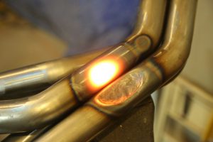
A few days later, when I could go out to the bus in daylight, I went out and removed the headlight switch from the dash. I could see one of the wires had become detached, but I was unable to see any truly fried wires. Puzzled, I plugged the wire into the open pin on the back of the switch, and tried the lights. Yep, headlights still turn on, dash lights still turn on.... running lights turn on. All of them, including the tail lights. So, I pulled on the hazard switch. Dash directionals flash, front directionals flash, rear directionals flash. At this point, I don't know what's fried, but the engine starts and runs, the cooling fans fire, the dash lights, switches and gauges work and all the lights work. In the middle picture, just above, there's a light blue orb thing on the lower left side of the image. That is a blue drip that I cannot account for, but I think something melted and that's the result. Neat.

I think it is time for me to determine which of the original circuits no longer need to be served and at the very least remove the fuses. After the cleanup I did in the back for running the engine, I think it would be wise to plan to do something very similar up front. I mean, in the end, the only things the "main" fuse box is running now are the dash, and the lights. That's like, 4 fuses tops? Regardless, this exercise should lead me to the smoked wire and reduce the electrical gremlins.

Furnace Update
furnace control board
Our electrician is semi-retired. He used to run a HVAC company and has installed literally hundreds of furnaces before focusing on general residential electrical instead. Now, as he is slowly divesting of his electrical business, he has observed my work on our furnace. In a fit of holiday fever (he swore off furnace work years ago), he popped by for a couple of hours, got the gas line hooked up and leak tested as well as the 110V electrical feed completed, with a worker shut-off switch. He even got most of the exhaust venting put in. He hit a wall when he was unable to connect the control cable because the access screws are hidden behind a panel that you can't get to once the first piece of exhaust venting is attached to the furnace. That's some poor design.

Still, I saw the furnace project as 7 big individual efforts: demo/move/mount, conditioned air distribution, cold air return, gas, electric, exhaust vent and the thermostat/control cable. I had completed the first 2. He knocked down 2 more (gas and electric) and set me up to get the next 2: thermostat control and exhaust vent. Once I have that done, he will confirm things, and test the system. Then, I just need to get the cold air to pull from inside the house and we have a complete system. For testing purposes, I may simply smack a filter on the plenum.

Since I started this thread, I caught a cold, celebrated Christmas and installed the thermostat control cable. As I indicated, I had to remove the exhaust venting all the way to the firebox before I could remove the panel which covers the control board. I ran a new wire from beneath the furnace (where the old one entered) and connected the control wires. Before putting everything back together, I took the opportunity to spray the snot out of the control board with a can of computer-cleaning compressed air. I figured that panel won't be coming off anytime soon, so may as well get the board as clean as I can. After that, it was simple replacing that which was removed, re-using the same fasteners.

That's about where things are today. Hapy appears operational, and I will be test driving him here in the next couple of days. The furnace is almost ready to test. I need to complete the assembly of the exhaust vent and properly suspend it from the floor to retain the correct exit angle, but I think that is a couple of hours effort at most.

Thanks as always, for following along. Have a peaceful, pleasant, hapy new year-

Tuesday, June 14, 2022

Enter the Headbanger (Part 3)

I thought I had gotten as far on the headbanger as I intended to for this camping season.... but, today, I wrap this puppy up. Pretty much. I designed, assembled and wired it in Part 1. In Part 2, I figured out how to mount it into the bus, filled in all the gaps with cardboard and applied trunk carpet everywhere a headliner would not be. And, of course, there was more wiring. Today, we complete the headbanger enough for use while we consider how and if it could be improved.

Before I begin, for my US readers, Hapy Flag Day. Earlier this year, I mentioned Phil and Phrends touring through the PacNW. We did that run, and I'll post on that adventure here shortly. But first, the completion-ish of the headbanger.

Headlining the Headbanger
The next logical step was applying headliner to the parts of the headbanger that were still exposed cardboard and OSB. I had a section of material that had been cut off the start of the roll that was about 2 feet deep (56" wide). I needed 19 inches. With the extra material, I was able to get the lines in the headliner to align with the bottom straight edge of the headbanger. I set the cabinet upside down on the tool cabinet with the rear edge facing me. I flopped the material over the speaker boxes and set the lines parallel with the rear edge. I rolled the material back on itself and applied contact cement to the OSB (2 coats) and then a light brushing on the headliner backside. I set the edge and flattened it with my hands. Once set, I rotated the cabinet 180* so the just-cemented part was facing away from me. I worked my way towards me, applying generous amounts of contact cement from side to side in about 6" wide swathes. I double-coated the cabinet, while single-coating the headliner. At each step, I smoothed the headliner down so there were minimal wrinkles and pulls.

With the main section covered, I considered the sides. I had enough material so I didn't need to cut completely separate pieces, but I would need a seam. I decided to make a long seam along the angled section rather than a short seam along the flat bottom at the rear. I did this for 2 reasons. First, the lines of the headliner run straight up-and-down like this, and they would have been running at an odd angle had I just folded along that edge. Second, I was having a hard time visualizing where to make the cut along that shorter edge. I made the fold, applied the headliner with contact cement and then cut off the extra floppy bit. In the end, I am not thrilled with the seam and will look for ideas for how to cover it with something visually inobtrusive. From a distance, it looks fine, I suppose.

All wrapped with headliner, I needed to remove the section in the middle. This cut was not my finest work, and after the less than perfect seams along the outer edge, these cuts further confirmed the need for something to clean-up the transition from trunk carpet to headliner. a small plastic 90* strip might work. Anyway, last, I cut the holes for the speakers and then poked holes through the headliner from inside the speaker boxes for the speaker mounting screws.

Install
I had hoped to have the headliner on the rear ceiling before installing the headbanger, but it's not in and I want to get Hapy on the road. So, I jumped to the install, and ultimately, this was a good thing. My method for raising the cabinet for install is unorthodox, but it worked. I set a plastic recycling tub onto the rear bed cushion. Onto that, I stacked the top and bottom cushions for the rock-n-roll bed. This wobbly stack sets the cabinet in the perfect spot to send through the rear bolts. These are all M4 bolts with lock washers and plain washers. These line up perfectly. Added to the left-center bolt are the grounding ring terminals for the USB chargers. I sent the bolts through enough to loosely hold the rear of the cabinet in place. While I could still reach them, I plugged in the speaker and the USB wires. Then I moved around to the front.

Up front, I discovered that the outer mounts were not going to work. The passenger side mount had the riv-nut in the wrong place (just barely, but wrong). The driver side mount riv-nut did not set, falling out as I tried to thread into it. I discovered that the location was too roundy for a riv-nut to really grab on after trying to set another riv-nut and failing. I know, I posted that I checked the alignment in part 2. I did, but checking the alignment and actually installing are 2 different things, and they are apparently different enough to matter. Lesson learned. So, the front is now held in place with 2 M4 bolts instead of 4. These were sent up the center, around the leading edge "gap filler". Now that it is all together and in place, that center gap fill probably could have been eliminated. As it is, it is very close to the rear light fixture. I may remove it in a later version, but it really does finish off that top edge, and it does pull the 2 speaker box sides together. As to the front edge mounts, I may send through a couple self-tapping sheet metal screws to help hold the cabinet up. It pains me to think that way, though, and as of right now, the cabinet it holding firm to the ceiling.

Once I had the front bolts torqued down, I torqued down the rear ones, and made sure the cables were tucked up out of the way. Satisfied, I pulled the rock-n-roll bed cushions and the recycling tub down. You can see the cushions through the rear window in the picture below.

Speaker Install
Installing speakers is not exactly new ground to cover. The only thing that made this interesting was that I was doing it upside down. Quick side-bar, though... I was able to get in and out the rear tail gate much easier than I expected to. In fact, it is easier to get in/out that way now, than it was 10+ years ago when the original 1972 Westfalia shelf was in there. Figure that I am not getting more nimble; this much smaller unit, and, with the angled front (front is front), it is not nearly as intrusive as the old shelf. I was able to sit upright on the bed (no rock-n-roll parts yet). I would wager that if I sat up suddenly in the middle of the night from a dead sleep, I would not slam my head against the underside of this cabinet. More and more winning.

Anyway, about the speaker install: One speaker at a time, I stuffed poly-fill into the speaker boxes... well, I stuffed poly-fill into the sides and corners of the speaker-boxes. Putting it anywhere else, it would have just fallen out. Then, I wired up the speaker and held it in place (with the cover) and screwed it into the headbanger. Repeat for the second side. Once wired up, I flipped the switch to turn them on and shazam, we have more sound blowing. Anxious to try it out, I closed all the doors, hopped into the driver seat and cranked up whatever was playing on the hard rock station at the time (Cowboy by Kid Rock). Wow. So much sound. After Kid Rock finished, Pink Floyd's "Dark Side of the Moon" started, giving me a sense of the system's fuller dynamics. This is gonna be fun.

Well, that's it for now. I will probably revisit the headbanger when I lower it to put the headliner on the rear ceiling. We are going to drive around like this for a while, though, to see whether we really need or want to change anything. Right now, it seems pretty great.

Thanks, as always, for following along-

Tuesday, May 24, 2022

Enter the Headbanger (Part 2)

The effort to design and build a custom headbanger cabinet took a while. And, there is a ton of detail, so I split this into multiple posts. Ultimately, this took me a few weeks of sporadic, and sometimes dedicated time, to do. At this point, I have the cabinet structure built, the speaker boxes attached and the speaker wire in place. So today, we solve for the mounting, finish the shaping, add trunk carpet and finish the electrical bits.

Plan to Mount
gap-filling
Prior to the assembly I described in Part 1, I rough-looked at a mounting plan. I took the cobbled-together OSB almost-a-cabinet out to the bus to consider how I could attach it. The cabinet was mostly stable, but I felt that adding the speaker boxes and other bits would help me plan for the mounting brackets. I couldn't be sure what I could reach or could not reach without actually having the speakers in, the shelf in, etc. With a considerably heavier cabinet, I headed out to the rear end of the bus. When I held a single speaker box in place, I used a rubber strap to hold it against the torsion spring for the rear hatch. That would not work this time. Instead, I stacked cushions and whatever I could lay hands on underneath it to wedge the cabinet up against the ceiling. It looked ridiculous and I regret not having taken a picture of the wobbly stand it was on, but I could think about where to place the brackets without a balancing act or having the cabinet shift side to side or front to back as I considered different angles.

I discovered that my initial measurements were slightly off for the inner supports, and I had to remove about 1/2" of the front-most 3 inches (front to back) off the top of the top-most edge of the 2 inner supports to snug-in against the ceiling. In the picture on the right, you can make out a small cut-away just above the chairback in the background. After some quick adjustments with a hand saw, I could return the head banger to the bus for fitment.
 
filling in gaps with cardboard
The cabinet is not terribly heavy, and even with the speakers installed, I don't think it will be more than, say, 20 pounds. While it is not a big deal overall-weight-wise, it is very front-heavy, and I think that will matter. Figure, the speaker boxes and the speakers are most of the weight and that weight is all front-of-center. So, the rear mounts will provide stability, but the front mounts will be carrying the weight. This is especially obvious in the picture on the right, here, where I have a roll of tape wedged under the passenger-side speaker box so it will sit flat on a table. I decided that I would put a bracket on all 4 supports up front. On the outer supports, the bracket will point out and on the inner supports, the bracket will point in. Any other orientation would have been unreachable because of the speaker-boxes. Either in the interest of consistency or overkill, I decided I would put 4 on the rear as well, but with the installs reversed: outer brackets facing inward and inner brackets facing outward. This was necessary to account for the added shelf running all the way back to the rear edge of the inner supports, effectively blocking my access to a mount point above in the rear.
 
I marked on the ceiling and on the cabinet where the brackets should go, and then took the cabinet back into the garage where I installed 1" angle brackets with wood screws. I returned to the bus with the brackets mounted and re-checked the spots in the ceiling where the holes needed to be bored in, marking them clearly with a sharpie. Continuing my avoidance of sheet metal screws, I bored the holes out for and then installed M4 riv-nuts. I confirmed the will-be-cabinet mounts aligned with the riv-nuts and then removed it so I could complete the cabinet. 

One More Thing
cardboard rear-support
While I was working on the ceiling, I prepared the install of the rear dome light between the 2 speakers. I had run the power leads earlier, and I was already there, with a drill. I laid down on my back, and considered where we would be lying down reading a book. Based on where a book would naturally rest in my lap, with my head propped up on a pillow, I figured where the light position should be, and marked it on the ceiling. I measured off of that to set the holes for the fixture, with the switches facing forward. I bored the holes and set 2 more M3 riv-nuts in place so the light fixture will mount with bolts, not screws. Again, that riv-nut tool kit is becoming one of my favorite new acquisitions.

Fill-in The Front
Once I had positioned and installed the speaker boxes, there remained a large gap between the top edge of the speaker box and the leading edge of the headbanger. I filled in this space with carefully cut firm cardboard that I then carpenter-glued into place. These stretches of cardboard will only serve as a backing for the headliner, but they are firm enough to hold in place. Since they are far out of the way, I think that once the cabinet is installed, the headliner and the underlying cardboard will go untouched for years. This pictures along the right side show the fill-in efforts, and how I created some support-from-behind with additional cardboard bits. I taped the seams as well, so the headliner lays down smoothly. After the glue set-up, I tested the relative strength of the cardboard bits by pressing on them with my fingers. They held firm enough that I figured they will hold up.

Final Assembly: Trunk Carpet
USB panel and ports
I was approaching the home-stretch, or at least it felt that way. It was final assembly time, and that includes final surfaces. I chose to use 2 different fabrics. For the areas where hands will touch regularly, like on the face where the USB chargers are and the shelf, I am using trunk carpet. I figure it will show a dirty finger less than headliner material would, and it is designed to withstand some friction. For all of the other surfaces (outer-facing sides, over the speaker boxes, the very bottom) will get headliner. They both apply with stinky DAP contact cement (or spray adhesive). I brushed both the trunk carpet and the target underlayment, wait a few seconds for the DAP to get tacky and set it. You only get one shot, so measure and plan carefully. I chose to use many small pieces, in contrast to the single complicated piece I used on Oliver's sub-box. To create some time to fiddle the pieces around, I used carpenters glue on the larger faces of the trunk carpet. It does not set up as fast, so you can wiggle the carpet into the exact right spot. Then, I did the outer 1/2" edges with the contact cement.
 
fun with wiring
Before carpeting the USB face, I installed the face to the cabinet with a staple gun and tapped the staples home with a framing hammer. To make sure everything stayed put, I edged the panel with carpenters glue. Once well-fixed, some trunk carpet went on. I cut out the holes for the USB chargers and the speaker switch with a razor blade and then installed them too. Before I repeated the install process with the shelf, I applied trunk carpet behind the USB face on the floor around the rear edge to finish the look. I also applied trunk carpet to the floor area behind the speaker boxes, around the inner supports and on the rear-facing side of the outer supports. I did not address the rear of the USB panel, so in that large black sea, there is this large white rectangle. Yuk. I'm not sure if there will be an easy way to get in there and "black" it. My goal was anywhere that could be seen or touched inside the bottom-most shelf from the rear hatch got trunk carpet. The result would be a view from the rear will be completely blacked out, and any use of the rear-facing shelf has dirty-finger protecting trunk carpet. That center section is virtually unusable from the rear so I may make a block-off insert to keep the look clean, and the wires from getting disturbed. The plate will wait. 

Final Assembly: Wiring
At this point, I wanted to finish the wire routing, so the rear-facing area was as tidy as I could manage. I ran the power and ground wires for the USB chargers out through the hole I had bored for the left (front is front) speaker wires, and routed them up the outside of that inner support, setting them immobile with staples. The speaker wires got covered in that black plastic wire wrap so they will not get caught on anything that is set on the rear-facing shelves and, because of all the black carpet, they will visually disappear. I verified that I had enough USB supply-side wire to reach the mid-point above the center shelf, added female wire connectors to them and then popped a chair-connector onto those connectors. 

Out at the bus, I added a male wire connector to the orange wire, completing the set up for the headbanger wiring. I also made sure that the speaker signal supply cables were long enough to drape over the right speaker, where the wires in the bus are. In the picture on the right, you can see just how much extra speaker wire I have hanging down from the bus ceiling. Why? So I can connect things before mounting the headbanger and then tuck the extra up above. Also, by having such long speaker wire leads heading to the stereo, I could unplug the headbanger and plug in a pair of float-remote speakers. Will I? Probably not, but I saw little harm in creating the option.

I was almost ready for the shelf. This was complicated a little bit by the OSB supports I had made. I wanted them to visually disappear, so I spent some time cutting and shaping small bits of trunk carpet to cover them. Finally, the shelf went in, as evidenced by the pictures above. Unlike the glue-on and staple fun of the USB charger face mounting, I wrapped the shelf with carpet and pushed it into place from the front. It is effectively held in place by friction.

The keen eye will notice that the trunk carpet needed some perfecting and trimming. I will address that before I get after the headliner install... which will wait until next time / later. I am feeling the time pressure, and feel the need to get this buttoned up soon. Phil and Friends is coming up fast and we don't have any interior lights or a stereo. So, this is where I am leaving the headbanger for now.... sitting on the rear of my US General rolling tool cabinet. I will get back to this, just not for a little while, probably. LOL's.

That's it for today. Thanks, as always, for following along-

Tuesday, May 17, 2022

Enter the Headbanger (Part 1)

It seems like the scope of Hapy's interior grows every week. I was just going to do a sound-containment effort, and it has grown in all directions almost from the jump. Today, I visit the furthest end of the sound system: the rear speakers. This little project actually took a few weeks to do, and this post got super long, so I split it into two. I will post the other half once I complete the work. Ha! Apologies for no post last week. I had spent the prior week visiting my son T in Los Angeles, and got back the Monday night before. Before I begin, Hapy Birthday Emily (my sister back East)!

How Did We Get Here?
headbanger from a 1976
So, I'm hanging out with Hapy, thinking about what to do next on the sound deadening one weekend morning and it occurred to me that if I were ever to want speakers overhead in the back of the bus, now was the time to wire them. Once the sound deadener is all the way in, snaking more wires will be much more difficult. While looking around at the furthest back part of the rear ceiling, I remembered that both the original Westfalia and the 1979 had a shelf or headbanger cabinet covering up the rear tailgate torsion springs. So, what had started as a "let's just run some wire" became "let's add a shelf/cabinet thing to hold speakers and cover up that rear-end ugly". More evidence that this bus will never be finished. I actually like that thought, but I'm weird.

Rear Speakers
speaker boxes
Recall, my earlier version of the rear speakers included a pair of speakers that basically floated around. When we were parked, we could move them out the slider for music under the canopy. I did not want to lose that capability, but felt that adding a pair of semi-fixed speakers back in the sleeping area would help the sound because we could actually dial-in our on-the-road sound based on those fixed speaker locations. I ordered a pair of Rockford Fosgate 6x9 speakers and a boom-mat from Crutchfield with a plan to flush-fit them into the lower ceiling, but.... ultimately, I simply could not bring myself to cut 2 big oval holes into the bus. I thought about a pair of 6x9 speaker pods from the guy who supplied the pods for Oliver a few years ago. Those were okay, but the 6x9 options seemed really big, and hung down over 4 inches. I found a speaker box that is curved on the back instead (picture on the right, here). I felt that these would give me more options for targeting the sound and they are quite small. The white lettering is absolutely atrocious, so I literally shot them with black spray-paint to cover it. If I could have gotten these boxes without carpet, I would have preferred that. I intend to cover them with headliner, because, while the spray paint removed the shocking white, the stitched letters are still visible. Wow, so ugly... but they will do the job.

The wiring for these speakers followed the line that the rear defroster wire takes: up the passenger-side A-pillar, and inside the lip along the ceiling. Behind the rear slider, they followed the course along the passenger-side ceiling.
 
Positioning and Modeling
rubber-strap thinking
I started thinking through options for how these speakers could integrate with the roundy rear end by hanging a speaker with rubber straps from the tail gate torsion springs. There is a support that runs from the lower ceiling back to the inner edge of the spring hinge on both sides. I used those supports as my outer edge fixed point. With a speaker in place, I checked the rear-view mirror. I tweaked the angle and tried again. I wanted the top edge to be within an inch of the ceiling, but did not want the lower edge to block too much of my visibility. I arrived at a viable compromise with the outer top-edge of the speaker sitting about 1/2" below the ceiling. Surprisingly, this "compromise spot" set the speaker fairly close to 45*.  This location would remove the top inch or so from the rear glass when looking through the rear view mirror. Based on the picture above, this is more than what is lost on the later bay-window Westfalia when the headbanger cabinet is installed. Can I see out the back? Yes. Will I be able to see out the back when it is packed with stuff? Of course not, but this cabinet is not the difference-maker; my packing ability is. Movin' on, the biggest difference in having this cabinet will be when I try to get in/out of the rear hatch or lean over the open engine access hatch. When I do either of those, I will be reminded why we call these cabinets headbangers.

With the position set, I shifted to solving for mounting. I started with some thin cardboard out of the recycling (surprise: I used a 12-pack box), measuring, cutting and fitting. This was not especially fruitful until I started marking up locations on the ceiling: inner edge of both speakers, and the center point both on the lower ceiling as well as on the upper lip of the tail gate. Now, with more reliable measurements,  I could determine a viable model. I planned for a shelf to run along the entire bottom, from outer speaker edge to outer speaker edge: 37" long, but only 5" deep. To help make the model better, I simply cut a 37x5 rectangle out of the remaining OSB from when I made the front shelf (See New Cab Shelf). With that shelf in hand, I modeled the supports with thicker cardboard. 

support modeled
The rear edge of the shelf required a 4" tall support. From the front edge of the shelf, the support will climb at a 45* angle. The supports on the ends will meet the ceiling directly. The 2 center supports, however, required an additional 2.5" of straight vertical to reach the ceiling, due to the curvy nature of the ceiling. The rear contour of the supports angle from the 4" drop up to 6.5" at the front (on the end supports) of the shelf before running straight forward. A few inches forward of the point where the lower line angles upward, the middle supports run straight up another 2.5" before running straight forward. The image on the right, here, shows the modeled shapes. I tested these with the OSB shelf, placing the cardboard on the spots I marked for where the speaker ends will be. Things looked good 'nuf.

From Cardboard to OSB
I took these cardboard cut-outs and applied them to the cut-up OSB, making 4 supports to go with the bottom shelf. After some fun with the jig-saw, I had 4 supports. This effectively used the remaining OSB, but I had enough to make the structure. Consider, between each of the outer and each inner supports, a speaker box will get mounted. Between the inner supports, I have an opportunity. My plan is to mount a pair of USB charger ports, another shelf and then enclose whatever is left. Since I am out of OSB, I will look to other materials I have lying around. Ultimately, the angled front face will get covered with headliner material, allowing it to at least visually integrate into the ceiling, and cover up the simply awful lettering on the speakers while I'm at it. Win!

glue-in the supports
Onto the base shelf, I drew the lines for where the supports were to be attached and confirmed again that the speakers would fit between. Then, I took the shelf and one-each of the supports and sorta-kinda test fit into the bus (keeping 3 pieces of wood held consistent with 2 hands is tricky). I felt satisfied that the lines, spaces and supports matched up with where I intended them to land, but, again, it's hard juggling 3 pieces of wood. When I built the speaker box for Oliver (See need reference), I learned that the screws were really not the key to making a solid box. The screws simply held the parts together while the carpenter's glue sets. Knowing this, I did not bother with screws at all; I used large clamps. Since I only have 2 large clamps, I did 1 support at a time: apply glue to both sides, set the support in place and then clamp both ends of the shelf overnight. The picture on the right here shows the last support getting glued in. Yes, that is one of those US General tool cabinets I posted about (See $50 Tool Chest) and that is Oliver in the background patiently waiting for dry weather and a trip to get smog certified.
 
More Planning
OSB supports
Now in one piece, I could plan for the USB chargers and such. I figure that the chargers are 2-1/4 inches in diameter, and we will need about a half an inch underneath it to snap-off the cover. To retain symmetry, I planned for a half-inch above, so I rounded up, making the USB face 3-1/2 inches tall. Because of the angle, I figured that the USB chargers would go on the lowest spot, since they take up the least amount of space. Above the chargers, I will put a shelf for setting the things that are getting charged (phones), and, again, because of the angle, the shelf being 3-1/2 inches up from the bottom will increase the depth of the shelf enough for a phone to fit without hanging off the edge, but only barely. The shelf doesn't really need a top, but to clean up the leading edge of the cabinet, I planned for a short drop front which I will cover with headliner. For materials, I have scrap bits of Oriented Strand Board (OSB) to make mounting points for the various flat surfaces. For the flats, I have one of the 1979 Westfalia panels I can cut up. Yes, I could save that for someone, and I could go find some veneer of some kind. But, this is free, and on-hand.

Some Assembly
I drew my plan onto the supports, and cut up a small pile (6) of OSB supports. With my limited number of clamps and vice-grips, I had to follow a similar pattern as I did with the supports: glue as many as I could support with what I have on hand and then wait a day. I oriented the 6 bits to support the USB charger ports and the small shelf directly above.

speaker prep
I then shifted to the speaker boxes. First, I prepared the boxes for speakers to get installed. I set a speaker and corresponding grill into the hole, marked and then drilled out the 4 holes. I set the speakers aside and returned to getting the boxes attached to the cabinet. These boxes deliver with wiring cups already glued in, but the location of the supports will completely hide them. I thought about boring holes in the supports, but decided instead to cut a small channel out of the speaker boxes and run the wire into that gap between the support and box. Then, I drilled 4 holes for each speaker, 2 per support, about 1/4" in from the long diagonal edge. Holding the speaker box in position, I drilled marks into the speaker box fabric, pulled the box aside and then completed the bore. I then returned the box to the cabinet and sent 1-1/4" long wood screws in to hold the speaker boxes in place.
 
For the shelf and USB charger surface, I measured out and cut with a razorblade the rectangular shapes. Into the USB charger surface, I bored 2 2-1/4" holes for the USB charger ports with a hole-saw bit on my drill.

Wire It Up
At this point, the weather outside was frightful. I wanted to take the cabinet out to Hapy to test fit, but I wanted no part of the wind/sleet/rain mix that was going on (it has been an interesting, albeit cold and wet, Spring in the Pacific NorthWest). I worked through the speaker wiring instead. We like the versatility that the plug-in speakers offer so, I added 2 plug-ports on the right rear edge of the cabinet. We will be able to add rear-facing sound our the rear hatch simply by moving the remote 6x9's. You can just see the rough-in plugs in the lower right corner of the picture below.
 
rough speaker wiring
Last, I wanted an ability to turn off the rear speakers from the back, without turning the whole system off. I figured, if there were a point where one of us wanted to take a nap, but the other was just hanging out under the canopy, the under-canopy person may still want some sounds. To resolve, we will fade the speakers to the rear, so the floating speakers still get signal, and then turn off the overheads. How? I added a STDP (single toggle/throw, double-post) switch. I wired the ground/negative-side of each speaker wire through the switch, and planned for the switch between the USB chargers (1/2" hole). The ports and the switch significantly increased the wiring complexity, but once completed, we have 2 plugs ready to plug into the speaker wires in the ceiling, a pair of fixed speakers overhead, a pair of ports for the floating speakers, and an override switch to turn off the sound signals passing into the cabinet.
 
I am going to stop here. Partly because this post has already gotten super long, partly because I have already spent a couple of weeks on this (and I post weekly), and partly because this is as far as I have gotten. I will complete the assembly, cover parts of it with trunk carpet, cover other parts with headliner and then get the cabinet installed/wired into Hapy. When I get all that done, I'll write and post "part 2". Maybe the weather will improve by then.

Thanks, as always, for following along-

Tuesday, February 9, 2021

Hapy Daily Driving

Well, that title might be overstating it a little bit. To clarify: Hapy is now capable of driving on a moment's notice. With the CoViD safer-at-home, I haven't been going anywhere. I may not have had an operable car for most of the last couple of months, but the lockdown has meant I haven't really needed one either. Today, I'll cover the little things that needed to be buttoned up after the big re-wire.

Reverse Lights
I mentioned the reverse lights at the end of the Electrical Gremlins saga. I had it wired up to a somewhat mystery switched 12V source before. When I tore the old wiring rats nest apart, it was left out of the new wiring. This resolution was fairly easy. Back when I set the mystery wire-up aside, I left the plastic-snap-shut fused wire in tact. So, there was just a plain bare wire to deal with. I fished it up into the spare tire well / wiring compartment from the engine bay. I spliced the wire into the switched source splice coming from relay 109 so the reverse lights will only come on when the computer thinks we are in "RUN". Since it already had an integrated fuse, this was a simple splice effort.

Headlight Flasher
When I was chasing the cause for my lack of amps during P0121 testing, I tore into the dash. I thought I had bumped something loose, and there are a bunch of things in there that could have shaken apart. Well, I didn't bump anything loose causing that issue, but I did bump something during that exploratory. Haha. During the Summer of 2020, I finally got my high-beam / low-beam flasher relay to work. It was because the replacement relay requires a source of 12V to pin 30. This pin wasn't on the old relay, and there is no wire leading to that pin in the original fuse box. I solved that before, but when I was looking for the buzzing noise during the P0121 effort, I pulled that relay and the wire heading to that pin fell out of the fuse box. I didn't notice that then. During post-testing, I discovered that the flasher no longer flashed. I found the wire, re-oriented it so it would not fall out, and returned things back to their prior cleaned-up state (zip-tied fuse-box). Hi-beam flash/relay works.

Defroster
Also in the Summer of 2020, I installed a defroster. Sort of. The defroster solution was moving the Vanagon rear heater under the belly, routing coolant along the driver side main beam and plumbing into the old air channel from just behind the front crossbeam. The air source was an experiment pulling from the old rear floor vent. The mechanical connection of the hoses to the heater was poor, and the experiment fell apart. This source needed to be remedied. Also, the switch was not operating the fan settings correctly. This was caused by poor quality wire connectors, so once the 3 at the switch and the 2 near the heater were replaced, we have a 3 speed fan again.

I decided that rather than solve for a cabin-source of air for the defroster, I would just remove the experiment for now. I have an idea for a source, but other cars need my focus. So, I removed the air supply hoses and called it good enough for now.

Mop Up
During all of the wiring work, the inside of the bus became considerably disheveled. It was one part shed, one part tool box and no part looking like a vehicle. This was easy to resolve, but made a huge difference in declaring the end of the work. The lot couch is back installed as a middle-row bench seat, for example. The rear speakers are hooked up and placed for sound again. After a quick trip with the shop-vac to get the wire-strippings and other fallout from all the work vacuumed up, he looked nearly ready.

I ran a test of the furnace, confirming that it would run on either the accessory battery or the main. It will, but the current draw for the glow-plug is so significant that I'm not sure I will want to start that heater if I am not running at least a float charger to the sourcing battery. Still, it moved the internal temperature of the bus from 43*F to 68*F (6*C to 20*C) in about 15 minutes. For the fuel-minded, it took about 500ml (or ~0.13US gallons or about 2 cups). As I understand it, maintaining the temperature requires far less fuel, so the consumption at that point dropped way off. I left it running for about an hour and the total consumed ml was about 530ml or 30ml (1/8 cup) for the remaining 45 minutes of keeping the bus warm.

I took one last step: I installed plastic kick panels I ordered like a year ago against the rear of the nose of the bus. Just like that, the cab looks like it is not an active project. It looks fairly clean now, actually. They install and remove easily, and once snapped in they really do not appear to need much more to hold them in place. The guy who makes them suggests poking holes through and screwing them into your bus. I might use Velcro, but I'll withhold decision-making until after we have had a few drives to see if they rattle or not.

Getting Legal
This last thing was actually one of the first things I did for Hapy after I set Zed aside. In fact, I think it was the registration that got me thinking about Hapy in the first place. His registration came due, and because of CoViD-19, I had to do it remotely. Since he is too old for smog and Oregon does not have inspections, I have been renewing his registration online for a few years. Still, this time I did the online steps in October 2020, but did not receive the stickers for his tag until January 2021. This used to take a couple of weeks at most. It sure felt good getting those stickers on his plates, though.

Test Drive
With the tags updated, the wiring fresh, the defroster responding, furnace functioning, etc... Hapy appeared nearly ready to be pressed into service. We just needed a test drive. For that, I did my usual neighborhood lap through a series of side streets out to the main drag, a quick 1-mile straight shot on that major street and then turning back into the side streets for home. As expected, Hapy was fairly peppy and responsive. He sounds great, and did not suffer any P0121 issues. There were a few stutters, but no codes, so I chalked that up to old diesel. That will solve with some snake oil and a fill-up. Considering that Hapy had not left the driveway in over a year, this drive was significant, albeit short.

Alt-Light
The battery light came on when the engine was revving low during the test drive, leading me to think that the unsettling "pop" noise I heard when the wiring was wrong (See Chasing the Hapy Electrical Gremlins - Part 6) was the sound of my alternator frying. This light had been popping on during testing, so the fact that it returned during the road-test honestly just reminded me. Before I jumped into anything, I in-bus tested the alternator: I alligator-clipped a fused wire to the alternator output and ran that wire on the ground up to the cab. There, I electrical-taped the bare wire to the positive probe of my multi-meter to free a hand. I set the negative probe into a small bolt-hole in the driver door frame for a good ground. First, a good base reading: 13.5V. Cool. I started the engine and it dropped down to 12.4V. Solid. With my hand on the go pedal, I revved the engine and watched the voltage climb up and down peaking above 14V. So, the alternator is fine. Since I have been running without an ALT/GEN light for 10 years, I could just ignore that light... Nah, I just can't do that. I figured that the bulb must simply be connected to the wrong wire of the 2 in the ALT plug.

I had spliced into the wire heading to the computer (DFM - or Digital Field Monitoring), and it needs to hit the one that routes to the cluster (L - Lamp). Simple fix: I cut the splice from the donor main harness to the 6-wire cable, and tied it into the other wire from the plug just upstream from the 4-pin plug. While I was back there, I added ring terminals to the sensor wires for the oil pressure and oil idiot light. There remains some wiring tidying I need to do on the driver's side, so I'll cut out the rest of the DFM-sourcing wire when I'm in there. 

As much as I'd like to say that once I completed, I took another test drive... I can't. I did test start and engine-rev in-place, however, just to see that ALT light wink out (which it did). Why did I not drive him? Well, remember Gramps (1996 VW Jetta 2-dot-slow from my folks that we gave to K2)? He re-appeared with a failed throw-out bearing after the first test drive, but before I'd solved the ALT light. So, I will have to juggle the herd to get Hapy free for a drive. And, you can probably guess what I'll be working on next.

That's it for today. While I may not need to go out much due to CoViD restrictions, I now have my beloved turbo-diesel powered microbus available-ish for whenever the need arises. While there are lots of little things I could tweak on Hapy, none of those things would prevent me from taking a drive. Sweet, sweet success. Thanks, as always, for following along.

Tuesday, December 17, 2019

Nemo Rides Again

Returning to the Nemo work, today we button everything back up and test things. In the first of these 3 posts (See Sadist Engineering), we diagnosed and removed the head. In the second (See Nemo Head Install), we took the head to a shop, had it tested and decked and then installed it back onto the engine. So, we start with the head and engine back together again, and torqued down.

Intake and Turbo
With the head on, next came connecting the turbo: slip a new gasket between, then slide the other 2 bolts through. I held the turbo from below and got those 2 bolts to thread in by hand. Once I was able to get them tightening down with a spanner, I could get the bolt closest to the head through to the turbo and finger-thread in. Tighten to spec. The intake was a bear to remove, but it was actually kind of easy to install (with a new gasket). I did not need to replace that one bolt, either. In fact, upon inspection, I couldn't easily distinguish it from the others. I was able to get them all snugged down tight. Torque spec was lower than I expected (like 20 pounds or something), so these were on too tight when I removed them.

Timing Belt
The last big/hard piece was the timing belt. Luke had really cleaned the head, so there weren't any paint-markings on the gear on the cam sprocket when I got it back. So, getting the belt in the exact same spot threatened to not be the simple case I had expected. I did know, though, that the engine hadn't moved and the head was at TDC, so I just needed to get the belt perfect-tight on the left side (front-is-front) and make sure I did not shift the engine timing when the belt was tightened. It turned out that I was smarter than I thought, and had put the head cam mark on the belt where the timing dimple appears on the gear. So, the alignment was actually a snap. That's one to grow on: mark the belt based on the timing mark and the shop can't erase them on you. I was able to re-use the belt tensioner (belt was replaced less than 20K ago) by slowly re-compressing it in a vice and sliding a paperclip into the hole to hold it compressed during install. Put on the tensioner roller, put on the tensioner verify everything is right and pull the pin. There are much better instructions with the belt kit than I could provide in this space. Regardless, once the belt is on, it is recommended to rotate the engine one full rotation by the crank and then verify that the timing marks are still spot-on. I apologize for not taking any pictures along the way, here. I got going and kinda forgot to.

Accessory Belts
After the timing belt is on, the lower timing belt cover is added and then the lower crank pulley. At this point, I put on the accessory belts, and the belt tensioner for the longer serpentine belt.

Hoses
With the timing belt and corresponding covers on, the hoses were next. Since I did not swap any hoses, and I removed as few ends as I possibly could, the hoses flopped back to where they were, and it was rather simple to plug hoses onto nipples. Getting the evil outlet flange on, though, was it's typical challenge. I used 10mm bolts instead of the Allen-keyed bolts and found them much easier to start and torque. I consider this an upgrade. Before I switched from cooling stuff, I mounted the overflow bottle.

Vacuum
Once everything else was in place, the vacuum lines just flopped into place. I didn't expect that, but I had only disconnected a few of them. I needed to find one that simply disappeared: the line from the intake manifold to the fuel pressure release. This is only about 4 inches long, and I had thought that maybe it wasn't on there when I started tearing things down. Turned out, I simply dropped it and found it on the tarmac after we moved the car. By then, I had put on a fresh hose.

Electrical
Re-installing the spark plugs was next for me. I could have done this earlier, but I got to it now, when I needed something that didn't require me to be bent over because my back was starting to flare up. So, I gap'd the plugs (.028) and installed them. Then, I plugged in the coil packs, bolted down the related grounds and verified everything I could reach was plugged in. I noted a few that could only be solved once the front end was re-attached, but that was becoming a very short list.

Front End Assembly
test ready
And just like that, I was ready to put the front cowl / radiator support back on. This would have been much easier with a helper, but I started with the passenger side, getting one of the upper bolts by the fender loosely threaded in. Then, I repeated the driver side. Now, I could arrange the large steel bar which runs behind / below the radiator and the lower mounting points of the cowl. Held in place with my knee, I set first the passenger side, then the driver side bumper supports with a single bolt. Bouncing from one side to the other, I threaded in the other bolts, and then tightened them down.

With the front end mounted, I could complete the hose connections to the radiator and confirm the route of the charged air. I swung the A/C condenser around and mounted it to the radiator and then added the large front inter-cooler. I plumbed the large pipes for the inter-cooler, and then checked for missing connections and not-plugged-in things. I plugged in the horns. I mounted the headlights and plugged them in. I found and plugged in a small green plug below the radiator and the sensor just above the lower radiator outlet. Or is it an inlet?

Test
I had run out of time and daylight to do anything else, but I knew the next step was to fill the system with water and test fire it. I wanted full daylight for that, and a night to sleep on it so I could come back and inspect with fresh eyes. The next morning, it passed visual tests and T dropped by for the test start. I filled the system with plain water.. yes, I know that's not a good thing to do long-term. This was simply to see if it started. I figured if it didn't I would be draining the system to fix it and didn't want to waste good coolant for that. We hooked up the battery and turned the key. Vroom-vroom.

We let the car sit and idle while the temperature came up. There were no drips so I ran my gloved fingers around the various coolant components. The gloves came back without moisture, so we took it for a spin. We drove for 15 or 20 minutes and watched the engine temperature rise and fall as we pushed it and let off. When we returned, we backed Nemo back into the service parking spot and let it idle again. No drips, no coolant loss. And, the temperature sat still.

Road Ready
We turned off the engine and did our little happy dance. The next day, I drained the coolant system and filled it 50/50 with G40 coolant and water. Once the system was burped of air bubbles, it was ready for T to take back home.

So, that's pretty much it for Nemo. I replaced a couple of fuses for the tail-lights, and the registration has expired, but otherwise, the car is ready. T collected the car, drove home to Eugene without incident and has driven it on errands and fun-runs multiple times since. We'll call that a win. Thanks, as always, for following along-

Tuesday, November 19, 2019

Nemo Head Install

Recall my prior post about Nemo, T's 1997 Audi A4 (See Sadist Engineering), I had exhausted all alternatives and had taken the plunge to remove the head to replace the head gasket. Today's post covers the re-install.

Head Shop
No, not that kind of shop, though I am in Oregon.... This head shop does work on the heads and block of your car. I looked around and found a small one-man operation 15 blocks from my house: Wilson Cylinder Heads and Machine. I figured that if he did good work (like according to the reviews), it would be really great to have a machinist so close. Keeping the money in the neighborhood is very important to me too, as you've probably noticed. Anyway, I dropped off the head and we talked a little bit about it. Since the car had not been misfiring nor throwing codes, he was not angling towards a rebuild. We turned it over and he could see that the center 2 cylinders had suffered coolant leaks, and figured that was caused by a head gasket failure. Remembering that the head bolts were none-too-tight, I was starting to think that the head was redone at some point by the PO and it was not torqued down properly. Recall, the PO did upgrade the suspension and the turbo, so maybe the head was redone at the same time? Anyway, Luke (the owner-machinist) went through the head, looking at the cam shafts and valves etc while he did the pressure tests and tests for cracks and other failures. The head came back clean. So, with a complete gasket kit in hand, but only a small subset really needed, I picked up the head and set to re-installing it.

Exhaust to Head
After the troubled removal, I decided that I would install the exhaust manifold (with a new gasket from that kit) to the head before putting the head into the car. While the head was at the shop, I scrubbed the manifold with sandpaper, freeing it of rust and then shot it with flat black header paint. It looks much better now. Before mating the manifold to the head, I put the turbo bolt which sits closest to the head through the manifold. It won't go through after it is attached. I installed all of the fasteners (random so they may be) and torqued them to spec. Once attached, the head is heavier, which is saying something because a fully loaded head is already pretty heavy already. I verified that the head was still in TDC position by setting the valve cover on, and checking the dimple on the gear aligned with the dimple on the cover.

Prep Engine
None of the online advice I have seen specifies the use of any liquid sealant for the replacement of a head gasket. It appears that this was popular in the past, but gaskets have gotten much better and tolerances have gotten much tighter, so if you are doing this and think you need a sealant applied to one side or the other (or both), double-check with the manufacturer of the gasket. It didn't look like the old gasket had any goop on it (not that you could really 100% tell), and the head and block surfaces were totally clean when separated, so I concluded that no sealant was used before. So, I also did not use any.


I did, however, need to clean the block mating surface. Using a razor-blade, I scraped off every tiny anomaly. I verified that the surface was clean by running a new blade around the surface, holding it completely perpendicular to the surface. Any resistance or even a change in the sound lead me to something that needed to be removed. This takes a long time. You can't rush quality, and spending the time here will pay dividends later.

Head Meet Engine
With a heavy head in hand, I thought about how to get the head to line up without damaging the head gasket. I tried putting a chop-stick into one of the head bolt holes in the block, but that only sort of helped. It did help me get my bearings, but, ultimately, I pulled the stick out before the real attempt. I found that random hoses or other things kept getting in the way, so I had to remove a couple of things I had not removed for the head removal in order for me to get the head to set. Most memorable was the removal of another coolant hose and pipe that wrapped around the rear side from the driver side to the front passenger side.

With the impediments removed, I could ease the head onto the gasket/block. I set it down gently and wiggled it lightly to make sure it set squarely on the 2 pegs on the exhaust side. I checked 2 of the head bolt holes with a chopstick, and confirmed that the stick set all the way through to the block. Knowing the head was aligned, I set new bolts through the head-holes. I finger-tightened them, then torqued to 30 pounds, 40 pounds and finally 44 pounds. With my breaker bar, I did 2 1/4-turns (spec says 1/2 turn past 44 pounds). I put a little dribble of oil on the cam lobes and a little dribble into each spark plug hole. I replaced the vale cover gasket and installed the valve cover.

This post got super long, and the content creation has taken most of the last few months. Why? Well, remember how I'm slow? Yeah, someone says it will take 2-1/2 hours. For me, we double their number and increase it a measure, so 2-1/2 hours means 5 days for me. That's 5 full days, like 40 hours. If you spread that out across weekend days, it takes a long time. I know that sounds like hyperbole, but have you read this blog? Anyway, I'll post back on this soon.

Thanks, as always, for following along-

Tuesday, November 5, 2019

Sadist Engineering

I'm taking a quick break from the TDI install retrospectives for a rant, and an update on the A4 efforts. We'll be back to our regular posts next week.

With modern cars, the effort to wedge more features and power into a steadily shrinking engine compartment makes maintenance increasingly difficult. Back when we had the Saturn (Dude), we learned that in order to change the light bulb in the speedometer, the dashboard needed to be removed. What? Yep, that's right; we didn't bother. There are plenty of examples of this, but today's post comes from the efforts to get to the head gasket on a 1997 Audi A4 1.8 Turbo.

1.8 Turbo Head Job
Once I ruled out all other possible causes for the coolant losses in T's Audi A4 1.8 Turbo, I started trying to find someone else to do the work. After 4 months of attempts, and numerous rejections, I finally got a quote from someone: $1250US. Since we paid less than that for the car, I couldn't do that, but we are unable to use or sell the car in it's current shape either. So... into the darkness we go. We start with the usual internet searches for steps and find very lengthy descriptions. Unfortunately, many how-to's neglect to mention key points in a timely manner (I'm sure I'm guilty of this too). For example, the best step-by-step I found did not mention that you needed to disconnect the fuel pump relay and run the engine to depressurize the fuel rail. So, once you got through 15 or so steps and you were told to dismantle the fuel rail... you couldn't. There's 100psi of fuel in there, and no way to safely depressurize it now because the timing belt is no longer on the engine, and the front end has been completely removed.. Sweet. So, rather than follow bad directions, or release fuel all over the engine bay and shop space, we get to go our own way where the fuel rail is not disturbed.

This is when we discover just how sadistic the German auto engineers really are... or were in 1997.

1.8 Turbo Intake
The intake manifold is held on with 10 fasteners: 2 10mm nuts, 2 10mm bolts and 6 5mm Allen bolts. The 10mm nuts and bolts are on the ends and the Allens are between the intake runners. Of course, they are also mostly obstructed by the fuel injectors, so, again, if you want to remove the intake, it is best to dismantle the fuel rail. Grr.. With a wobble-head attachment on my 3/8" ratchet, I was able to crack all of the bolts except one. That one bolt eventually broke free after throwing various bits at it. I will need to replace at least that one bolt for re-install.

1.8 Turbo Exhaust
With the timing belt off, the evil coolant flange removed and the intake separated from the head (with shop towels covering up all openings), we shift to the exhaust side. The exhaust manifold is held on with 2 13mm nuts, 2 12mm nuts (yes, that's right. we've got both kinds of nuts) and, on this car, 3 6mm Allen bolts and 3 13mm bolts. I say that because someone swapped out some of the 6mm Allen bolts and replaced them with hex bolts. Now, the car is usually equipped with a heat shield which is held on with Allen and hex bolts. This car did not have the heat shield but all of the bolt holes were occupied with hex bolts which were in place nice and super-tight. Ugh. Love PO's. Regardless, the nuts are on studs at either end of the head, making them hard to get to, driving you to using old-skool spanners especially near the firewall. Once removed, I shifted focus onto the Allen bolts, and things got interesting. The exhaust manifold is very short, wrapping into a turbo that sits almost directly in front of the lower mounting bolts. So, from above, you need to thread a long Allen key between everything and torque the bolts free. Penetrating oil and long-stemmed Allen sockets recommended. Even then, you can't reasonably get to all of the Allen bolts under the exhaust manifold.

The best solution is to remove the turbo from the exhaust manifold and pull the head with the manifold still attached. Then, you can get after those Allen bolts. The turbo is held to the manifold with 3 17mm bolts. These bolts point straight up and have a slight recess around them in the manifold. Water likes to build there when the car is parked outdoors, so what do you get when you leave water standing on iron? That's right. Rust. Enter the penetrating oil again while you think about how you're gonna get a socket onto those bolts. Realizing you can't, again, you go old-skool with a spanner. I was very grateful for my penetrating oil comparison (See Hammered Rims Part 1) when I discovered the Kroil. After a few days of spray-and-wait, those bolts came off with very little extra coaxing.

Head Out
With the intake off, all the other little bits remove, the outlet flange off and now the turbo released from the exhaust, there was nothing more in the way. Except the valve cover and the 10 mystery head bolts hidden within. The valve cover is held on with a bunch of 10mm nuts and bolts. Once removed, the cover should just lift off, but nah. I applied some convincing with a rubber mallet and then with a pry bar on each corner. With the pry bar, I made sure to apply very light pressure so I didn't crack anything. With the valve cover off, we could see what king of fastener held on the head. After the swap-about on the exhaust, I couldn't just assume based on make-model-year. Turned out the bolts were the 10mm RIBE-style, so they could have been original. Regardless, these are typically sold as part of head gasket kits. With a bit in hand, I made to remove them and this was my first indication that the head had been removed at some point. I put my torque wrench on, and they required very little effort to loosen. By "very little effort" I mean I put my torque wrench on there and gave it a good bump with my hip and they broke free. I should have needed a breaker bar.

With the bolts all loose, I was able to wiggle the head. So, I put fingers into the coolant outlet, and my other hand around the belt tensioner and pulled straight up. It came free, and dropped the head gasket out as the head lifted out. What I saw was very interesting. The coolant passages rising up from the engine block met the gasket, but the hole in the gasket wasn't the same size as the hole in the block. The gasket has a little pin hole and the block was a decent-sized triangle. While I thought this was the application of the wrong gasket, according to Fel-Pro, it isn't. This is by design to correctly meter the coolant through the engine.

I will be taking the head to a shop to get pressure tested, decked and otherwise refreshed while I clean up the block face. The coolant passages look like some build up occurred behind the gasket, so I'll clean that up with a pick and a shopvac (so no bits fall deeper into the engine). I'll return to this effort blog-post-wise once I have the head back and the install is happening.

Thanks for following along. More next time-

Tuesday, October 23, 2018

MGB Exhaust Re-Do (Part 2)

Picking up where I left off, we have the MGB front end on jack-stands and the old exhaust sitting in a heap in the driveway. Today's post will be about getting the new exhaust installed. Recall, it is a ceramic-coated stainless steel Bell system. I left the packing plastic bags on the pipes as I handled them to protect the finish, removing the plastic as I installed them.

Setting The Scene
exhaust hammer example
from streettechmag.com
With break time over, we set to trying to install the new exhaust. The Bell system has 5 pieces: the header, a straight-ish pipe, the center resonator, another straight-ish pipe with a support bracket attached and then the tail muffler. They go on in that order. The hardest part, like with any car, is getting the header to fit around all of the various other things in the engine bay. I watch car shows on Velocity and some of those installs require hammering on the pipes to get them to fit. That would really suck. Spend all that money for a "bolt on" set of pipes and then have to dent the snot out of them to fit an otherwise stock engine and compartment. Doesn't seem right, but does explain the custom fabrications they do on some of those Velocity shows. Even then, it's usually because they're slamming a huge non-stock engine into a classic-ish car. For a built-for-stock engine, hammering dents into the pipes shouldn't be necessary. Anyway...

From Below?
For the MGB, this saga starts with getting the front end way up in the air. We had a good 18" of clearance and still couldn't feed the header up from below. Some internet posts I've read indicate this is super easy, but I suspect anyone who installed that way had a lift or a pit. We have neither so we switched to going in from above. That meant removing the bonnet.

From Above
attached for fitting the rest
of the pipes
The bonnet is held to the hinges with 2 bolts per side, but remove the hood prop first. Once the prop is off, one person holds the hood still from the front while another person (K2 in this case) loosens all the bolts, and removes one from each side. At this point, it would be wise to put a shop towel or something soft under each rear corner of the hood. Then, remove a final bolt from one hinge. Balance the hood on your shoulder and let it slide down onto the towel. Repeat with the other side and then each person grabs a side of the hood and walk it off the front. For fun, we set it (on pads) on top of the 280ZX hood. The MGB hood looks like a toy hood compared to the Zed hood. The MGB hood is at least 6 inches smaller all the way around.

center-mount bracket
With the hood removed, you next loosen the driver side engine mount. The two nuts which hold the engine to the mount are the easiest to get to, and present the least necessary to separate the engine from the frame rail. With nuts safely stowed, place a wood block on a floor jack and slide it under the driver-side of the oil pan / engine block. Carefully lift the engine from below (setting the block of wood so the oil pan and other parts are not damaged) an inch or so. Once you feel considerable resistance to the lift, stop lifting. Now, have your helper fit a pry bar between the engine mount and the engine and then apply pressure to shift the engine slightly towards the passenger side. The engine will more roll anti-clockwise than slide left-to-right, but this creates enough space. Hold the header vertically, with the head-tips pointing across the top of the engine. Slide the header as far down into the largest space you can go before rotating the header so the head-tips point up and away from the firewall. On this particular header, there are pinch-welds along the sides of the collector. These pinch welds wanted to hang up on pretty much everything on the way down. With some gentle and some not-to-gentle persuasion, the header pushed past the space between the block, the steering column and the frame allowing us to wiggle it into the right spot near the head. At this point, the pry-bar leverage can be released and the floor jack released, letting engine rest back on the mount. We had to wrestle it a little bit, but it settled. Our header ended up with a couple minor scuffs, but no scratches.

To get everything else to align, K2 bolted the header onto the head. K2 was done for the day at this point, and the rest of the install was not going to be as straightforward, so I cut him loose.

Body Brackets
header from below
While K2 attached the header to the head for fitment / alignment, my focus was on the 2 mounting brackets. The center mount reuses the original body mount holes with a new steel and rubber mount that simply threaded in with new bolts (in the kit). The rear mount also reuses the original body mount holes. If yours are still in great condition, you could reuse them. With the body brackets on, I could start lining up the pipes, and get a feel for what went where.

The fourth pipe (second straight-ish) had a bracket that was a simple flat bar wrapped around the underside of the pipe with a round hole at each end. The center-mount kit provided a bolt, 4 large flat washers, 2 plastic sleeves, a bit of metal flashing with holes and some small nuts and bolts. There were no instructions, but you could tell that the bolt went through the holes in the flat bar. A flat washer went between the flat bar and anything else that touched it. Between the ends of the flat bar, on the bolt, went the plastic sleeves and the nut went on the end. Neat. With some careful bending of the flat bar with my channel-lock pliers, I was able to get the operation together. The bit of metal flashing was to wrap around the plastic sleeves and then bolt to the center-mount bracket I had just attached to the car.
second straight-ish pipe mounted

To get the fourth pipe and centermount to align and fit, all of the pipes between that mount and the header need to be in place. Start with getting the pipes in the rough spot you expect them to be. A straight-ish pipe (one that has a gentle bend or two) has those bends for a reason. Align them with the path of the original pipes. Once set in the right location, fit a pipe clamp between the pipes and then slide them together, wiggling the fit so they stay together and are in the right alignment. With careful use of a rubber mallet, I was then able to drive the various pipes together. Remember to set a pipe clamp at each junction before you start pounding things together or you won't have a way of clamping things together.

Rear Muffler
The final hurdle was figuring out the rear muffler mount. The old mount was a real hack job where a prior owner had taken a u-bolt that roughly fit the original body mount and threaded a nut on each end. So bad, but I really shouldn't judge. The original mount was almost German in it's over engineered solution. To the bracket is attached 2 rubber mounts pointing away from the exhaust pipe. To these rubber mounts, a hexagon bracket (with one leg removed) is attached, with the missing leg on the bottom. The missing leg has a pair of holes, one at each end, for attaching a pair of semi-circular clamps. These clamps hold the pipe in place. Unfortunately, they are sized such that if you put them on without any spacers (not included) they will either pinch the exhaust pipe because you tightened them too much or the lower clamp will fall off because you didn't tighten them enough... because you didn't want to pinch the pipe. To remedy, I found a pair of oversized nuts that would slip on, acting as spacers, so I could tighten everything down without pinching the pipe.

Header to Head
see the gap?
Once I had it all assembled front to back, I moved from back to front, tightening the mounts and pipe clamps. Once snug, I shifted to the very front to consider the mating of the manifolds to the head. The MGB came with a few types of exhaust, with 2 particular versions for the models before emissions standards became so tight (in 77) that the exhaust manifold needed to be redesigned. These 2 types have a different thickness of the material through which you send bolts to attach it to the head. The older one (#12H709) is thicker than the newer one (#12H3911). This is important because the intake and exhaust share studs and corresponding nuts. If the thickness of one manifold is not a match for the other, there is not a uniform amount of torque on the various manifolds, creating leaks. This applies to pretty much any combination of intake and exhaust, unless you stay completely original stock. Since the prior owner had replaced the dual carbs on my MGB with a side-draft Mikoni carb, and hacked together a home-grown exhaust, I was going to have to deal with this regardless.

When the header was attached for fitting the other pipes, I didn't look very closely. It didn't matter. With a closer look, you can see the washers were not sitting flush. Adding insult, only two of the thickness differences for the 4 shared studs were the same. To remedy, I grabbed some fender washers of varying thickness, and cut them in half (across the hole) to use as spacers. To hold the spacer in place during install, I used a very thin smear of the copper gasket maker I used on the header gasket. This plan worked great. In about 30 minutes I had spacers in place, and the header torqued down with washers sitting flush.

gap gone
Testing
All of this, nearly 2 full days of effort, lead up to the test fire. Of course, I had to re-assemble the air cleaner, and the hood is still off, but after verifying everything was back together, it was ready. I had been trickle-charging the battery, too, so I was pretty confident it was going to start right up. Fortunately, it did. It sounds great. It has a nice deep tone without being too loud. The biggest difference, I think, is that all of the growl sound comes from the rear of the car now. It must have had leaks before. With all of the rust, that's not a surprise. I wound the engine up to 3000RPM to get a sense of how it will sound on a power pull and it sounds pretty awesome. With the top down, the garage doors open and the rev counter around 3k, I still hit 90+ dB. So, it is no quieter... in the garage with the doors open. On the road, it is quieter in the seat, but I don't have dB numbers to prove it. Just my ears.

That's it for today. I had started reading about how to do automotive interiors (trimming) in preparation for doing the seats and cards on the MGB. I have parts on-order to complete the trunk and woofer box as well. Once those are complete "major operations" will have completed and I will be shifting focus onto the Zed... and then back to Hapy. Thanks, as always, for following along-