Showing posts with label hose. Show all posts

Tuesday, March 26, 2024

Fixing Hapy Furnace (part 2)

Picking up where I left off the last post, Hapy has an operational furnace again.

Fuel Pump Swap
As I mentioned in my last post, the fuel pump which originally delivered with the heater/furnace would not work when I tried to bring things back to life. I splurged and bought a more expensive "quiet" model for $50US rather than another standard pump for $20US. I figured quieter or not, the more expensive pump may have better parts in it, and it may last longer whether it is quieter or not. Or it was just a marketing gimmick and I got took. Let's chalk it up to the cost of an experiment.

The old fuel line path was relatively simple. The "hard" (clear but firm plastic) lines that delivered with the furnace had short (50mm / 2-inch) stretches of fuel hose between them and the pump. The pump was suspended from a cross beam by the included rubber mount held in place by a single sheet metal screw. After a few turns with a screwdriver, the pump was on the ground. A few more and the fuel lines were removed from it. The supply fuel line started dripping fuel after a few seconds, so I caught it with a pan. The line on the pressurized side was completely empty, so no drips. I simply reversed the removal: added the rubber mount from the supply end of the pump, added the supply fuel line, suspended the pump from the cross beam and then added the pressurized-side line.

Prime and Fire Up
The Afterburner has a control page where you can direct only the fuel pump to fire up. This allows you to get fuel all the way to the furnace without the glow plug turning on (drawing the battery and maybe burning out the glow plug). I had not connected the pressure line to the furnace, but I wanted to clear the lines of any bad fuel, so I moved the pan under the dangling hardline and triggered the Afterburner to prime. Within a minute of the prime starting, fuel started spurting out the end of the line. It took longer than I expected it to, but perhaps that is an indication of how little fuel these units actually consume. Once the fuel leaving the pressure line looked like the fuel supplied at a filling station, I stopped the prime function and connected the hardline to the fuel hose dangling from the furnace.

While the pump was slightly larger than the original, it did not seem much quieter during the prime. Of course, I hadn't heard it pump in a couple of years, and memory is a funny thing. I do recall that when the furnace was running, I could hear the tick-tick-tick of the fuel pump over the whoosh of the furnace. With this in mind, I set the furnace to start. I did not want to consider the experiment with the new thicker, dedicated wiring yet, so I left the battery tender hooked up. At no point did the battery fall below 13.5V so either the tender was working hard, or the new wiring is a hit.

Regardless, the glow plug got lit, the fan started spinning and after 2 or 3 minutes the furnace ignited. This felt like a considerably longer period of time than before. Perhaps the priming was incomplete and I needed to prime again after connecting the hose to the furnace. Perhaps it took time to ignite simply because it had been so long. Once it ignited, a huge plume of smoke poured out of the little muffler. There was virtually no wind, so the cloud grew and sat slowly obscuring first the rear end of the bus and slowly 2/3 of the bus before a light breeze broke it up. After a few minutes, the cloud dissipated and the exhaust emission was reduced to nothing. All that remained was a light smokey haze inside the bus. I regret not taking a picture of that.

Noise Observations
While the temperature inside the bus slowly crept up from 55*F (13*C), I noted the noises. I could only hear the fuel pump ticking inside the cabinet where the furnace is located and even then, only when I stuck my head into the cabinet. I think the pressurized line is transmitting it. I stuck my head into the rock-n-roll cabinet above the spot where pump is actually installed and could not hear it. Maybe this new pump is quieter. Then, I moved outside where in the past I could clearly hear the pump from several feet away, even from the passenger-door side. I could not hear it, but I could hear the furnace whoosh. Of course, my muffler-ing of the furnace is different this time, having removed the second small rectangular muffler and the motorbike muffler. Perhaps the pump is no quieter, but the furnace is that much louder. To determine if the muffler configuration is a variable, I decided I will conduct another test at a different time, after re-attaching the other muffler bits. I had thought about bringing them along for while-parked use, and maybe I will need to, out of respect for our festival-going neighbors. In the past, I took decibel readings, but they were for while the furnace held a temperature, not during temp catch-up (full blast).

I will continue to experiment with noise readings and post if I find any readings are different than they were 4 years ago. I expect that once I put the extra rectangular and motorbike mufflers on, the readings will be what they were before. The only real mystery to me is whether the fuel pump can be heard over it. At this point, though, the pump seems significantly quieter.

Thanks, as always, for following along-

Tuesday, March 19, 2024

Fixing Hapy Furnace (part 1)

Having finally arrived at a place where we have some heat while we're moving, I felt motivated to fix the heat for when we are standing still. Today's post covers most of the saga of getting a Chinese diesel heater operational again. Spoiler alert: the heater isn't running by the end of this post.

Brief History
Back in the early days of CoViD, I installed one of those Chinese diesel parking heaters into Hapy (See Parking Heater 1, 2, 3, 4, 5 and Final for deep detail). While I was able to run it a few times, I found that the heater pulled the voltage way down on whichever battery was connected to it. I tried to solve by providing multiple batteries to source from: one to start, one to run, but switching from battery to battery seemed like a bad practice. I had other priorities, so I just let the furnace sit unused. When I did the sound deadening effort and the luxury electrical re-wire, I dismantled the cabinet which housed the furnace so I could get sound deadener underneath it and electrical cables through it. This meant dismantling part of the furnace too. Later, when the band wanted to use Hapy for the album cover, I removed the furnace exhaust so it would not appear in pictures. So, I had a furnace without an exhaust, and would draw way too much juice.

Electrical
Over time, and with more learning about electrical stuff, I have concluded that the wire used to convey electricity but perhaps more importantly the wire for a ground were far too thin. It was due to these thin wires that the voltage would drop so badly as the furnace attempted to compensate. Wires which would have been barely up to the job had the battery been sitting right on top of the heater will definitely NOT be up to the task once you move the battery a few feet away. This is exacerbated by running the ground to the body of the bus instead of back to the battery. The ground location should not matter as much, but I'm citing it as a participant cause anyway. So, addressing the electrical came first after removing the furnace from the bus.

A small harness of wires leaves the furnace body and enters a black plug (see picture on the right). The harness that ships with the furnace includes a pigtail that clicks into the furnace black plug. To my eye, the red and black wires in the pigtail are not nearly as thick as the wires leaving the furnace. This probably saved the manufacturer a few pennies, but the amp draw issue starts right there (and in my case got worse). So, I cut the main power and main ground wires from the furnace black plug and put male/female wire ends on them (12V/ground respectively). I made them different so I couldn't accidentally plug it in backwards. I then prepped a thick 2-wire black/red cable with matching wire ends, and routed it over to the luxury battery. At the battery end, I added a ring terminal for the ground and added a 20Amp fuse into the positive side before adding a ring terminal on that end. I left things detached as I switched to preparing for the exhaust.

Exhaust
From under the bus, it was clear that I had not made the hole(s) large enough for the exhaust, intake and fuel to be easily maintained. Quite the contrary, I had installed it such that once it was all together, it would have to all come apart to fix anything. Frowny-face. So, I started by cutting a 4-inch square hole into the lower belly pan. Many buses do not have these, but I got lucky. Anyway, with the hole cut I could see where the furnace sat, and noticed that the exhaust was getting pinched by the too-small hole in the floor as the exhaust left the furnace. So, I went topside and expanded the upper hole both in the floor of the cabinet and the steel floor of the bus. With the larger hole, the exhaust easily fits and things could be maintained from below. Still, I did what I could on the furnace itself before lowering it in: Connect a 6" long stretch of fuel line, attach a small circle of window screen to the intake (so bugs and pebbles don't get in) and then attach maybe a foot of heat-wrapped exhaust. I set the furnace in place and attached a small subset of the muffler arrangement I had used before: just one rectangular muffler. I may bring the expanded muffler set up for use when we are in tighter camping spots (like festivals), so we can bolt-on some extra quiet. I mounted the muffler to the underside of the frame rail, with the outlet pointing rearward and slightly away from center (picture on the right).

A keen eye can see some fresh Rustoleum primer + paint above the muffler where I discovered some rust had eaten all the way through the body. When I was working on the other stuff I ground the metal down, removing the rust, but exposing the holes. Sadness. That rust traces back to when this bus had a small vent window directly above this spot. That vent window was badly leaking and the rust had already been forming to the point of marring the paint when I bought this bus over 20 years ago. I eliminated the vent window in 2015 (See Calling "glass") with a window I purchased from BusBoys in Redding, CA in 2009. Some things move slower than others.

Fuel
I shifted over to fueling at this point. The fuel line that had been between the included "hard" line and the furnace had breeched, probably when I did the sound deadening. The fuel in the line looked dark, so I dropped the line into an empty pail, and figured I would prime the fuel system, and purge the bad fuel at the same time. Unfortunately, the fuel pump is no longer functional, so I am waiting on a replacement to finish this job.

Afterburner
Back when I first did this job, I bought an Afterburner from the guy who hand builds them in Australia. Apparently, there are people building knock-offs, eating into his business, since they basically have cloned his work. So, if you are looking at getting the much nicer controller for your parking heater, please connect with Mr. Jones in Australia and get the real deal. Anyway, with the Afterburner, I tried to prime the fuel system, but the fuel pump wouldn't respond. When I unplugged the pump, I got a code; I concluded the wiring to the pump was good but pump was bad. So I ordered a new, supposedly quieter, one. We'll see. While I was clowning around with the Afterburner, I got it onto my home network, downloaded the newest firmware and wandered around the new-to-me website that the Afterburner hosts. It's really cool. I am looking forward to triggering the furnace to warm the bus from inside. For reference, here is a link to the user manual.

This is as far as I've gotten. I am waiting for a new fuel pump to arrive. I need to purge the old lines of nasty fuel, and install that new pump. I expect there will be other discoveries, and I need to rebuild the cabinet innards. There's always opportunities to improve things. Anyway, thanks, as always, for following along-

Tuesday, February 22, 2022

Burying the Brake Reservoir

This shorter-than-normal-but-actually-reasonably-length'd post was originally included within the second Hapy Seating post (See Hapy Seating - Part 2). I pulled it out into it's own post because the content stands on it's own, and the seating post was pretty long even without this. So, today, I will document the moving of the upper brake reservoir in the 1972 VW Bus.

Stock Reservoir
before image
Consider the original location of the upper brake reservoir on the 1972 bus is a tab/perch that juts forward from the driver seat partition. I clarify it by year because from the pictures I have seen, the reservoir appears in different places for different years. In Hapy's case, this perch sits, maybe, 6 inches off the seat floor with an opaque hard plastic hose attached to the bottom. The hose has a bulb at the top, allowing it to fit over the nipple on the reservoir. It is held on with a plastic clamp, and there is a rubber sleeve between the inside of the hose/bulb and the outside of the nipple on the reservoir. This opaque plastic hose runs down to the seat pedestal floor, and passes through a special hole in the floor of the pedestal. Within the pedestal, there is a cavity about 4 inches across between the inner wheel well of the driver front wheel and the outer edge of the pedestal. The opaque hose runs downward into this cavity and out a hole in the floor of the bus. Underneath, the hose runs forward about a foot to the master cylinder, upon which is another reservoir, that the hose attaches to. The hose connection to the lower reservoir is the same as the connection to the upper reservoir: bulb, clamp, rubber sleeve. Between the bulbs, the hose is narrower. The picture on the right, here, is from Hapy before I replaced the hose the last time. Note the rust, but more importantly, note the tab on the partition. Also, near the lower right corner of the rear-most square opening is the round hole through which the original brake reservoir hose passes. I do not have a picture of my original, complete, assembled set up, nor can I find any examples on the interweb. Trust that a square-ish reservoir hangs on that tang and connects to an opaque hose that passes through that round hole.

Gimme a Brake... Reservoir... Hose
pre-paint test mount
A while back, when I took that picture above, I purchased and installed a replacement opaque plastic hose between the remote, upper, brake reservoir (behind the driver seat) and the sitting-on-master-cylinder lower reservoir, but I did not shorten it to fit. It was "the" hose that was available, and was described as the right part for all buses and Vanagons. One size fits none again as the upper reservoir did not sit where it was supposed to. Just to hold it still, I zip-tied it to the driver seat partition through a pair of factory threaded holes near the top crossbar. It was not pretty, but it was functional and it didn't leak. So long as the driver seat was pushed back, no one could see how ratty the solution was. 

I wanted to fix this ugliness. I had mentioned the location of this reservoir in passing in the first post about the Sprinter seats (See Hapy Seating). I thought about the reservoir, it's location and the hard plastic backside of the 2016 Sprinter seat, concerned whether the brittle plastic reservoir in the original position would get run into if the seat was pushed back to the partition. Fairly sure the two unforgiving plastics would hit each other, potentially cracking the much older reservoir, I moved it inside the pedestal of the front seat. It can now be accessed through a pre-existing square-ish hole in the pedestal, near the rear of the seat. The picture on the right, here, shows the new location. I may get creative with a cover when I do the carpet or I may leave it exposed, but that's a decision for another day.

Re-Locating the Brake Reservoir
I started by MityVac'ing a bunch of brake fluid out of the hose, down below the stock mount point. Before I made the decision to simply move the reservoir, I tried to shorten the plastic line. I cut the hose, heated it up and tried to force-jam it onto the filler. Yeah, that doesn't work. I could not figure out how to make the "one-size fits Vanagon - otherwise you're on your own" hose to fit. Additionally, the plastic is too hard to wedge a 2-sided nipple in a line breach, so a simple cut and double-barb solution wouldn't work. I abandoned that plastic line and started seeking a rubber line solution.

reservoir in service
The hose barb on the original reservoir accepts a 12mm hose. Flexible 12mm brake hose is not easy to find in lengths greater than 4 inches around the usual online sources for some reason, and those short sections are crazy expensive (like $8US before delivery charges). However, a half-inch hose is only .7mm bigger, and those are plentiful, here in the US. So, I ordered a 2 foot length 1/2" Department of Transportation (DOT) -rated brake hose, and ran it from the master cylinder up under the driver pedestal, through the original hole in the floor. The hole through the floor needed to be expanded, however. I do not have drill bits that big so I used a sledge-hammer and an old 2-ton floor/trolley jack's removable handle (as a chisel) to smash the hole larger. Yeah, that felt a bit destructive, but it only took about 4 or 5 whacks with my small sledge to drive the jack handle through. The jack handle was completely unmarred by it. Once expanded, the hose slid through the hole.

I fit the upper connection first, and completed with a clamp. The hose settled onto the plastic nipple, but I unexpectedly needed to use a touch of force. I had thought that .7mm would have allowed the hose to slide on and slop around. I was pleasantly mistaken. Then, I slid underneath and figured out the correct length of hose. Once the length was decided, I cut it with tin snips, and mounted with a clamp. I mounted the upper reservoir to the side of the seat pedestal last, filled it with brake fluid and checked for leaks. I stepped on the brake pedal a few times to create some pressure. Finding no leaks, a firm brake pedal and feeling quite satisfied, I called it complete.

Oh, the 2016 Sprinter seat easily slides back over the top of the reservoir with plenty of room to spare. Like multiple inches to spare. As to what would have happened had I pushed the seat all the way back, I'll never know for sure. But, the rear of the seat comes within an inch of the little tab thing, so they would definitely have collided.

That's it for today. More next time-

Tuesday, October 5, 2021

Resolving the Stammer

In the 2 major trips I took this Summer (2021), my road reports focused mostly Hapy's handling, the wind and the traffic or road conditions. I mentioned, sort of in passing, about the engine stumbling or stammering, having an error code thrown, and the occasional blanket of smoke. Today's post covers how I resolved this condition.

I should call out that the last trip of the season (for Hapy's birthday) did not include a code being thrown. He struggled into the headwind on the way there, but cruised with a tailwind on the way back. In neither direction did he throw a code nor dump smoke, but there were bumbles. So, I did this maintenance so the next trip would not be wanting for power.

P1550
Let's start with the code that was getting thrown: P1550. This indicates: Solenoid Valve for Boost Pressure Control (N75) - Control Deviation. in short, the thing that controls the turbo is not behaving consistently. So, the turbo is dumping boost to protect the engine. The result is a loss in power, sometimes a considerable loss. When I first noted the stumbling engine, I assumed it was fuel related. I replaced the clear fuel filter, because it had some stuff in it, but while that may have helped with consistent fuel delivery, it did not meaningfully address the engine stammering.

As I reflect back on the drives, we should have had WAY more power. I just got bigger nozzles and had the computer chipped. We should have been flying down OR-22, limited solely by the completely soft setting on the adjustable shocks. Instead, I was back to climbing hills in 3rd. It didn't register while we were driving, but it is now. Since we were sporadically getting a P1550 code, the turbo was sometimes dumping boost on the ground.... and creating a nice smoke blanket in the process.

Vacuum Lines First
stock hoses
Throwing parts at a problem is one way to solve it. Most people don't like resolving that way, though. When you have vacuum issues, which a P1550 error code usually means, there are some parts you kind of need to throw at it. If you only want to change the one thing that's wrong, you need to check all of the vacuum lines and appliances (turbo wastegate, N75, N18, EGR, ASV, vacuum ball, brake line, etc) and replace the one that is not holding pressure. The least expensive solution is to disconnect and re-connect all of the hoses. Sometimes they work themselves loose, and when you put things back together again, they just work. While cheapest and least guaranteed, this is also the least satisfying path.

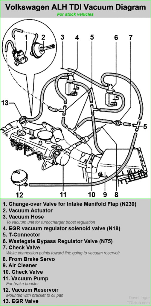
If your vacuum lines are over 10 years old, like the ones on Hapy are, then you are due for replacing the lines anyway. Many of Hapy's hoses removed with little effort, almost falling off. Others were brittle and baked on and some others looked like they could have been replaced a couple of years ago. My hoses were following the stock pattern, but the other 2 valves (for Exhaust Gas Recirculation - EGR and Anti-Shudder Valve - ASV) were just blocked off. So, I switched to the simplified version (image below, courtesy of DaveLinger of TDIClub), leaving the unused valves in-place and wired, but without a vacuum source. This should reduce the opportunities for vacuum leaks to appear in the future.

There are kits on the 'net for a couple of meters of 3mm hose and a couple of meters of 5mm hose. The 5mm is for the line from the N75 to the bottom of the turbo and from the N75 to the air cleaner. The rest on Hapy are 3mm, but from looking at the diagram, I would expect that the line from the "T" to the N18 should also be 5mm. All of the lines I removed from Hapy were 3mm: I didn't have any 5mm when I did these 10 years ago. I am sure the VW engineers used the bigger diameter hose for a reason, though, so I installed 5mm hose to/from the N75. Anyway, replace one hose at a time, cutting the old hose off by slicing along the plastic nipple (to avoid breaking it). This will cost, like $30US, in hoses and in about an hour your hoses will be good as new. Possibly better. P1550 possibly fixed.

Brake Booster Line
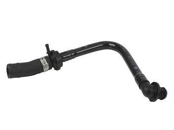
So, you still have a code or lack of power? Next, I would replace that big vacuum line from the vacuum pump to the power brake. These age and crack like the others, but the replacement is not in the hose kits. For another $30US, you can replace this. I was about at this point when I kinda remembered that my brakes were not as responsive, and I had to push harder to get the bus to stop. Sometimes. I had thought it was weight-related and even hit a trucker scale on the way beck from 4Peaks to see if I was especially heavy (4400 pounds, btw). I wasn't. Perhaps I was stopping with only partial vacuum boost or even power boost free. Hoping the power booster on the brake was not the cause, I continued down the path of parts I had on hand. My hose was original, and while there was a little cracking at the vacuum-pump end, it looked pretty good. Still.. you can't tell if a hose is failing by looking at it. Glad I replaced it.

Replace the N75
no EGR, no ASV
Last "inexpensive" thing to look at is the N75. I put quotes around it because it is still $70US. I suppose the vacuum ball or the little grey/white check valve could be the issue and these are fairly inexpensive. If you are still getting the p1550 after all the replacements above and the N75, you may have an issue with the wastegate actuator, or your brake booster. Remember the booster failure on Oliver, the MGB? For reference, here are the links for the finding and the fixing posts. 

Replacing the N75 is usually as easy as replacing the hoses. 3 hoses and a 2-pin plug-on-a-cable connect to it. It is held to the firewall with a couple 10mm bolts. I ordered both the hose kit and the brake booster line as well as a N75 when I attacked this problem. Since my engine is a first-year ALH, the 2-pin plug is different from most others, so the N75 on-market does not direct swap in. The plug needs to be re-wired or the pins pushed out of the old / into the new. I left the N75 in my supply heap and just did the lines. I figured that if I need to cut some wires or play with the pins, I want to be sure that it will actually solve a problem, rather than just create work. I had to remove the air intake to get to the vacuum lines so I cleaned the air filter while it was in-hand.

Test Drive
With the vacuum lines replaced and simplified, I was ready to see if the stammering issue had resolved. Prior to doing this work, I was still driving Hapy around as my "daily" driver (quoted because with the pandemic I don't actually drive everyday. Maybe I should say my "weekly" driver), and I was still getting sporadic stammering issues. So, I figured if I could just drive to my favorite burrito place (Taqueria El Gordo) without a stammer, I'd have solved the problem, and gotten dinner. I say that because it is just far enough away for the stammering to appear. Even if it didn't solve, I would still have a killer burrito. It was on a drive to Gordo's that I could easily re-create the stammer problem within a short trip, so I figured it was a decent test-track.

What's that saying about "the best laid plans"? Well, instead of going to the burrito place, Boo and I drove right past it and out to Cornelius (west of Hillsboro) to see some live music. Hapy suffered no stammering, and he had plenty of power. I didn't really put my foot into it, but he popped off the stop lines well. At no point on the drive there and back did he stammer, nor lay down smoke. I am calling this solved: failing vacuum lines. 

That's it for today. Thanks, as always, for following along-

Tuesday, February 9, 2021

Hapy Daily Driving

Well, that title might be overstating it a little bit. To clarify: Hapy is now capable of driving on a moment's notice. With the CoViD safer-at-home, I haven't been going anywhere. I may not have had an operable car for most of the last couple of months, but the lockdown has meant I haven't really needed one either. Today, I'll cover the little things that needed to be buttoned up after the big re-wire.

Reverse Lights
I mentioned the reverse lights at the end of the Electrical Gremlins saga. I had it wired up to a somewhat mystery switched 12V source before. When I tore the old wiring rats nest apart, it was left out of the new wiring. This resolution was fairly easy. Back when I set the mystery wire-up aside, I left the plastic-snap-shut fused wire in tact. So, there was just a plain bare wire to deal with. I fished it up into the spare tire well / wiring compartment from the engine bay. I spliced the wire into the switched source splice coming from relay 109 so the reverse lights will only come on when the computer thinks we are in "RUN". Since it already had an integrated fuse, this was a simple splice effort.

Headlight Flasher
When I was chasing the cause for my lack of amps during P0121 testing, I tore into the dash. I thought I had bumped something loose, and there are a bunch of things in there that could have shaken apart. Well, I didn't bump anything loose causing that issue, but I did bump something during that exploratory. Haha. During the Summer of 2020, I finally got my high-beam / low-beam flasher relay to work. It was because the replacement relay requires a source of 12V to pin 30. This pin wasn't on the old relay, and there is no wire leading to that pin in the original fuse box. I solved that before, but when I was looking for the buzzing noise during the P0121 effort, I pulled that relay and the wire heading to that pin fell out of the fuse box. I didn't notice that then. During post-testing, I discovered that the flasher no longer flashed. I found the wire, re-oriented it so it would not fall out, and returned things back to their prior cleaned-up state (zip-tied fuse-box). Hi-beam flash/relay works.

Defroster
Also in the Summer of 2020, I installed a defroster. Sort of. The defroster solution was moving the Vanagon rear heater under the belly, routing coolant along the driver side main beam and plumbing into the old air channel from just behind the front crossbeam. The air source was an experiment pulling from the old rear floor vent. The mechanical connection of the hoses to the heater was poor, and the experiment fell apart. This source needed to be remedied. Also, the switch was not operating the fan settings correctly. This was caused by poor quality wire connectors, so once the 3 at the switch and the 2 near the heater were replaced, we have a 3 speed fan again.

I decided that rather than solve for a cabin-source of air for the defroster, I would just remove the experiment for now. I have an idea for a source, but other cars need my focus. So, I removed the air supply hoses and called it good enough for now.

Mop Up
During all of the wiring work, the inside of the bus became considerably disheveled. It was one part shed, one part tool box and no part looking like a vehicle. This was easy to resolve, but made a huge difference in declaring the end of the work. The lot couch is back installed as a middle-row bench seat, for example. The rear speakers are hooked up and placed for sound again. After a quick trip with the shop-vac to get the wire-strippings and other fallout from all the work vacuumed up, he looked nearly ready.

I ran a test of the furnace, confirming that it would run on either the accessory battery or the main. It will, but the current draw for the glow-plug is so significant that I'm not sure I will want to start that heater if I am not running at least a float charger to the sourcing battery. Still, it moved the internal temperature of the bus from 43*F to 68*F (6*C to 20*C) in about 15 minutes. For the fuel-minded, it took about 500ml (or ~0.13US gallons or about 2 cups). As I understand it, maintaining the temperature requires far less fuel, so the consumption at that point dropped way off. I left it running for about an hour and the total consumed ml was about 530ml or 30ml (1/8 cup) for the remaining 45 minutes of keeping the bus warm.

I took one last step: I installed plastic kick panels I ordered like a year ago against the rear of the nose of the bus. Just like that, the cab looks like it is not an active project. It looks fairly clean now, actually. They install and remove easily, and once snapped in they really do not appear to need much more to hold them in place. The guy who makes them suggests poking holes through and screwing them into your bus. I might use Velcro, but I'll withhold decision-making until after we have had a few drives to see if they rattle or not.

Getting Legal
This last thing was actually one of the first things I did for Hapy after I set Zed aside. In fact, I think it was the registration that got me thinking about Hapy in the first place. His registration came due, and because of CoViD-19, I had to do it remotely. Since he is too old for smog and Oregon does not have inspections, I have been renewing his registration online for a few years. Still, this time I did the online steps in October 2020, but did not receive the stickers for his tag until January 2021. This used to take a couple of weeks at most. It sure felt good getting those stickers on his plates, though.

Test Drive
With the tags updated, the wiring fresh, the defroster responding, furnace functioning, etc... Hapy appeared nearly ready to be pressed into service. We just needed a test drive. For that, I did my usual neighborhood lap through a series of side streets out to the main drag, a quick 1-mile straight shot on that major street and then turning back into the side streets for home. As expected, Hapy was fairly peppy and responsive. He sounds great, and did not suffer any P0121 issues. There were a few stutters, but no codes, so I chalked that up to old diesel. That will solve with some snake oil and a fill-up. Considering that Hapy had not left the driveway in over a year, this drive was significant, albeit short.

Alt-Light
The battery light came on when the engine was revving low during the test drive, leading me to think that the unsettling "pop" noise I heard when the wiring was wrong (See Chasing the Hapy Electrical Gremlins - Part 6) was the sound of my alternator frying. This light had been popping on during testing, so the fact that it returned during the road-test honestly just reminded me. Before I jumped into anything, I in-bus tested the alternator: I alligator-clipped a fused wire to the alternator output and ran that wire on the ground up to the cab. There, I electrical-taped the bare wire to the positive probe of my multi-meter to free a hand. I set the negative probe into a small bolt-hole in the driver door frame for a good ground. First, a good base reading: 13.5V. Cool. I started the engine and it dropped down to 12.4V. Solid. With my hand on the go pedal, I revved the engine and watched the voltage climb up and down peaking above 14V. So, the alternator is fine. Since I have been running without an ALT/GEN light for 10 years, I could just ignore that light... Nah, I just can't do that. I figured that the bulb must simply be connected to the wrong wire of the 2 in the ALT plug.

I had spliced into the wire heading to the computer (DFM - or Digital Field Monitoring), and it needs to hit the one that routes to the cluster (L - Lamp). Simple fix: I cut the splice from the donor main harness to the 6-wire cable, and tied it into the other wire from the plug just upstream from the 4-pin plug. While I was back there, I added ring terminals to the sensor wires for the oil pressure and oil idiot light. There remains some wiring tidying I need to do on the driver's side, so I'll cut out the rest of the DFM-sourcing wire when I'm in there. 

As much as I'd like to say that once I completed, I took another test drive... I can't. I did test start and engine-rev in-place, however, just to see that ALT light wink out (which it did). Why did I not drive him? Well, remember Gramps (1996 VW Jetta 2-dot-slow from my folks that we gave to K2)? He re-appeared with a failed throw-out bearing after the first test drive, but before I'd solved the ALT light. So, I will have to juggle the herd to get Hapy free for a drive. And, you can probably guess what I'll be working on next.

That's it for today. While I may not need to go out much due to CoViD restrictions, I now have my beloved turbo-diesel powered microbus available-ish for whenever the need arises. While there are lots of little things I could tweak on Hapy, none of those things would prevent me from taking a drive. Sweet, sweet success. Thanks, as always, for following along.

Tuesday, May 26, 2020

Parking Heater - Final

In March, I posted a series about installing one of those inexpensive Chinese Diesel Heaters into Hapy, the TDI-powered microbus (See Parking Heater 1, 2, 3, 4, and 5). I have completed the little things that I had left undone, so today's post takes a break from the oil temperature and pressure stuff and wraps up the heater.

Power Switch
I had left off with a power switch wired between the main (drive) battery and the heater. It was dangling around in the cabinet behind the old refrigerator-turned-cabinet. I added a wire to the luxury battery housed under the rock-n-roll bed through the fuse box I have controlling circuits to that battery. I also bored a hole into the wood support I have in that rear cabinet holding the old westy battery maintenance panel. I don't really use that panel, mostly because I haven't finished wiring up shore power to charge the luxury battery. Anyway, I punched a 5/8" hole through and fed the switch through, nutting it down. It looks fairly finished now; it just needs a label.

Cabinet a Cabinet Again
floor back in.
The heater sits on the floor of the old refer cabinet. I only need about 7 inches of clearance, but I gave it 8-1/2 so I could add a layer of insulation later. At the 8-1/2 inch point, I attached 2 wood supports running along the front and rear walls. On top of these, I put a thin run of foam to reduce any noise or rattling, and then settled a rectangular board for a cabinet floor. In the future, I will probably attach some kind of insulation to the bottom of that floor. For now, it is just a bare piece of wood.

The smaller cabinet can still hold quite a bit of stuff. I re-stowed the zombie-apocalypse Red Cross first aid duffel, some paper products, and a few other fairly important yet random things (playing cards and a cribbage board, for example).

Afterburner
Afterburner installed
Afterburner unpacked
The Australian guy (Ray Jones) who makes the Afterburner appears relatively unaffected by the CoVid-19 lockdown, so he was able to process my order and sent it to me. Bear in mind, he is a one-man operation, so the waiting list can be rather long. I let the package sit for a few days in quarantine (on concrete garage floor) before digging into it. The included install instructions are easy to follow, and all of the parts are easy to identify. I had it installed, complete with wire routing and final wall mounting in a couple of hours. I have only scratched the surface of what this thing can do, but I am very impressed with it so far. In my opinion, the white case and grey buttons looks great. Like so many other improvements, this shows me how much I can raise the aesthetic simply by adding carpeting to the wall cards. All of the scratches in the picture on the right, here, highlights how overdue this is.

Afterburner operating
Okay, today's post was a little light, but all combined, those short passages took me hours to complete. More important, the heater is complete. Once I have the Afterburner figured out, I'll be able to pre-heat the bus in the winter time, have the heater turn on based on a schedule, shut off based on temperature, etc. Basically, it will have the same capabilities as a home thermostat... but in a 50 year old VW bus. This heater install was originally so we could get warm during the summer solstice music festival in Bend (4Peaks) which would have been next month had the CoViD pandemic not happened. Assuming everything is back to normal in June 2021, we will use it there. Maybe, just maybe, next winter I will be able to achieve my old dream of taking Hapy to the mountains for some fun in the snow.... now that we have a way to get the cabin warm. Hmm.. maybe I need to figure out how to add a defroster first.

Thanks again for following along. More next time-

Tuesday, March 3, 2020

Parking Heater (Part 5)

How this concept took more posts to cover than the rebuilding of the front end of the MGB, I don't know. But, here we are, a fifth post about it. Wow. Let's start with re-capping what the prior 4 posts have covered.
Part 1 - why I'm doing this and what's in the box. Also some early, uninformed ideas about needed upgrades
Part 2 - planning, ripping up the old refer cabinet, placing the fuel line and fuel pump
Part 3 - planning a heat register, connecting the fuel line to the heater, sourcing the power and then an air filter boondoggle.
Part 4 - connecting the exhaust, installing the heater unit, completing the fuel system, completing the electrical and the heat register

So, what's left? Routing the exhaust, the inbound combustion air and running some tests.

Exhaust Wrap'd
fuel pump gets vertical
Until now, the exhaust has simply flopped on the ground. Obviously, that is not a viable long-term solution. So, after watching some interesting video footage of various muffler styles (courtesy of John McK), I made some decisions. JohnMcK stressed that the intake and exhaust must be left as open and clear as possible for long-term health of your heater. It was this advice that had me abandon any muffler wadding. He was also confirming what Hal said. JohnMcK was the source of the info to orient the pump as vertical as possible as well (see picture to see how mine is now oriented). I was going to conduct a bunch of noise experiments, but JohnMcK already did that for us. I encourage you to watch his videos; he is super-dedicated to these things.

So, post JohnMcK love-fest, I decided to use 2 of those little thought-they-were-garbage "muffler"s. Based on JohnMcK's findings, they each drop the dB by about 10% and when placed in series that continues (so 60dB drops to 54 which then drops to around 50). I had already acquired a flow-thru motorbike muffler, and John tested one of them also. They didn't seem as impressive as they looked, but I intend to use one anyway, since it will help to hide the others.

only shiny things in sight
The "muffler"s need to hang vertically because they each have a drain to let out moisture and/or unspent fuel. Unfortunately, they are hard to hide, especially since they are shiny and there's practically nothing shiny on this bus. The underside is particularly NOT shiny, so these "muffler"s will be very visible. Consider that the heater exhaust exits the bus a foot or so forward of the rear driver-side wheel, fairly close to the outer edge/lip along the side. Because of the short distance between the exit point and the wheel well, in order to route sound muffling, the pipe needs to run forward and then turn back on itself (exhaust must point rear and down or the air-flow from driving will create back-pressure). JohnMcK stresses the importance of having no more than 270* of bend in your exhaust or you may create too much back-pressure. So, this gets interesting. I planned the locations of the "muffler"s and pre-drilled holes in the belly pan to hold the "muffler" hangers. They are about 6 inches inboard of the outer lip.

wider context view
As the pipe leaves the bus, it turns 90* towards the front. I cut it off at that point with a hacksaw, cutting the heat sleeve with scissors first. With the help of a stainless steel reducer (3/4" to 1" with the 3/4 inch inside the cut pipe), I mated the cut-off pipe to 2 "mufflers" in series, connected by a cylinder of HVAC flashing held in place with pipe clamps. Yes, that sounds hinky, but it is actually quite solid. To the end of the second muffler, I slid on the clean end of the included exhaust pipe I had just cut off over the "muffler" end, leaving the ragged cut end free. I added more heat sleeve and another clamp at the "muffler". I then turned the pipe into a "J" so it faced more towards the rear and stopped to test, and to get noise readings. The pictures here paint a better picture than my prose.

Inbound Combustion Air
Apparently, these heaters don't need an air cleaner. I find that very hard to believe. Still, going with it, I decided to remove the air hose from the intake side of the heater, using the large cavity between the floor and the belly pan to act like an insulator against really bad stuff getting in there. I was having fit issues anyway, and this removed the thing that was in the way. I will be attaching a bit of window-screen to the intake, but for testing purposes, it currently has no filter. That's how JohnMcK does it without a filter, so I'll not argue. As it is, there are a few spots where air could get in, but only one 1" diameter opening so the route to the inside of the heater would require some form of intelligence to get there.

Testing
motorbike muffler added
With the exhaust completed enough for testing, I fired up the heater and let it run. I checked dB levels (reads as "quiet house" within a few feet of the exhaust, bouncing around 55dB) and wandered around for a sense of sound impact. I am unable to hear the fuel pump at all outside of 15 feet (5 meters) away. The sound of the heater running disappears into outside noise after another few feet. Within the bus, the pump cannot be heard over the sound of the fan except at the lowest setting. I let it run for about an hour and the temperature inside the bus climbed from 12C (about 54*F) to 20C (68*F), while at the 3 pulse-per-second setting, around the mid-point. I kept getting in and getting out, leaving the slider open sometimes, etc, so this is not scientific. Still, since the bus had not been over 60*F since last Summer, I consider a nearly 15*F increase a fairly significant feat. It will be interesting to see how effective it is when I really just let it be. One thing worth noting: the exhaust has no smell. None, and no smoke either. I cupped my hands at the exhaust outlet and breathed it in just to see if I could get any smell. Nope. That's efficient.

My last test was to fire up the engine of the bus to confirm that I did not interrupt the fuel supply to the engine. Obviously, that's kind of important and arguably could have been done sooner. Honestly, I wasn't sure he would fire up, but he did on the first try. Good boy, Hapy. I drove around the cul-de-sac but he dropped into that 1200RPM can't-read-the-throttle mode, so I parked him again. Looks like he's trying to tell me that the next thing needs to be resolving his electrical.


Well, I think that's enough talk of the Parking Heater. It really isn't completely done. I did the install of the motorbike muffler with exhaust hangers to help make the exhaust look nicer. It does end up a little quieter, now in the low 50's at the boost or high-power setting rather than low 50's at mid-power, so that's good. You can see how it appears in the picture to the side here. Not sure it actually looks that much better, but the cut off pipe looked pretty janky. I will be installing a false-floor in the cabinet so it can be used as a cabinet again. I will be attaching the power selector switch to the bus as well as running a power line from the luxury battery. I intend to put some kind of heat insulation on the register to retain heat, and might add some air baffles to direct the air flow a little. I don't think any of those warrant a 6th post, though. Then again, one or more might appear on their own if I have nothing else going on, or they become more involved than I thought. Oh, one last thing: I found a guy who makes an after-market thermostat/controller for these things, called Afterburner. I intend to experiment with one of those, if I can get my hands on one.

Thanks, as always, for following along. If you have more questions about these heaters, I fully endorse JohnMcK's videos. They are incredibly informative.

Tuesday, February 25, 2020

Parking Heater (Part 4)

Picking up where I left off last time, I was in the middle of the install of one of those cheap eBay parking heaters that are a rip-off of those $1000US jobs. I have a partially constructed custom heat register, the fuel line run from the engine compartment through the fuel pump to the heater unit. I have holes bored for the combustion air intake and exhaust. Last, I have the unit grounded and the 12V source almost together. So, while lots of things are not done, they are all just a few steps away. I didn't quite finish it today.

Exhausting
making register
I had already worked the combustion air intake hose up through the holes from under the bus. This took a few trips in and out of the bus to get the hose to bend and not hang up as it passed through. If you have a helper, even a reluctant one, this is where s/he would really give lots of help for very little effort. With sufficient hose pushed through to the inside of the cabin (I gave myself about 6"), I switched to the exhaust. First, I slid the bendy stainless steel hose into the heat sleeve. The sleeve is 3' long, and it is much longer than the stainless steel exhaust hose/pipe; I will have extra. I got the sleeve as tight around the pipe as I could and slid it up through the holes from under the bus. These holes were more aligned and a little larger than the intake, so it went through with little fanfare.

Once through, I could start connecting the air and exhaust to the heater. The air hose was more willing to be managed, and connected without much effort. The exhaust, however, took some doing, but I got it on, and the sleeve pulled all the way to the top, and then clamped the pipe and sleeve to the heater output with one clamp. In the process, the fuel line popped off, so it needed to be re-attached. For now, the exhaust and intake pipes are laying on top of a car-ramp so they aren't sitting on the pavement in the rain. I'll button them up to the underside once everything is working and after the noise experiments indicate what muffler solution to use.

Heater In
heater in
With the underside connections to the heater all buttoned up, I was ready to press the heater into place. First, I set the heater above the hole and pushed a little bit. Say, 10 pounds of pressure. Then, similar to the run-around I did for the air intake, I got under the bus and tugged on the hoses a little bit. Again 10 pounds of pressure or less. This took some of the excess bends out so I could then press the heater home from inside. I checked again from below just to be sure. I then attached the unit to the bottom of the cabinet with a pair of wood screws and then tried to shake the heater. It wouldn't budge.

Fueled
Next, I needed to complete the connections for the fuel. I had intended to locate the "T" close to the front (front is front) of the engine compartment, but once I got in a position to work on it, I made a small change. The large clear filter was already in a fairly good space, and I figured that I could fit the "T" just downstream of the filter without cutting any fuel hoses. I took the "T", pressed on a short (2" long) stretch of hose on one end, and a 2" stretch of 4mm hose on the small part of the "T". I clamped the other end of the 4mm hose to the trimmed end of the heater fuel line. Then, I squeeze-sealed-off the hose between the clear filter and the large filter with a vice-grip. I was now able to remove the line from the clear filter and then quickly connected the short stretch of hose from the "T" to it. To the other end of the "T" I connected the vice-gripped line. All clamps were snugged down and then I removed the vice-grip, but fuel didn't really move around. The net result has fuel leaving the small clear filter and immediately enter the "T" fitting. The large end of the "T" continues on to the Caterpillar filter while the small (4mm) end of the "T" routes to the heater.

Priming
foamed and screwed
I should note that the picture in the last post of the fuel pump needed to change. The directions give no indication of the fuel flow direction, and that pump is one-directional, pulling towards the end which shares the electrical plug. That's the case with mine and while they may not all be the same, my viewings on YouTube of the little heater professor (John McK) implies that they are all the same. I was also alerted (again by Hal) about the orientation of the fuel pump in my post a few weeks back. So, I re-checked it, and he was right, I had it practically horizontal, and they need to be approaching vertical for the fuel to lubricate the piston inside the pump and for the little bubbles created during the pumping to float up into the heater. I disconnected the heater-side from the pump, shifted things around, and re-connected.

I left the fuel line at the supply-side of the fuel pump disconnected, however. To this line, I connected the Mity-Vac to fill it with fuel. Once the Mity-Vac jar was steadily filling, I stopped the vacuum and quickly reconnected the line to the pump. I checked the clear filter in the engine bay and it was full, so we should have a nice tight system now.

Complete Heat Register
When I last touched the heat register, it was a box, but it needed to be sealed and it still needed a 3" pipe connection. I got a 4" connector from Home Depot, and cut it open. I could have probably used some basic flashing, but thought the dimples and wrinkles would help hold the air hose on. I fit the cut connector into the hose, marked with a pen and then cut the connector so it fit a 3" diameter hose. I also cut about 1-1/2 inches off the end to make more maneuvering room in the cabinet. I fit the connector into the register from the inside, and pushed the seating tabs down. Once set, I used metal HVAC tape on all of the seams on the register, including the connector. You can see the finished result in the top picture.

register completed
My rough forming of the register resulted in the outlet not being completely flat. I tweaked it for a few minutes and got it close, but I knew I couldn't get it perfectly flat. To resolve, I put a thin strip of foam along the edge which would be pressed against the cabinet. Then, I threaded one screw per side through the register edge to hold it to the cabinet. I took it out to the bus, and pressed it into service.

Last for the heat outlet, I needed to run the air hose from the heater to the register. This was relatively simple. I laid out the hose to check length, cut it with a pair of scissors, and clamped it in. It took some wrestling.

Finish Electrical
With the fuel ready and the heated air routed, all that was left was connecting the final electrical bits. First, I completed the wiring from the fuel pump. By now, the switch I had ordered had arrived, so the rest was just as easy. I connected the center post to the heater supply-side and the fused 12V from the main battery to one of the outer posts. Then, I plugged in the controller and the heater.

Tests
The moment had arrived. After charging the battery, I flipped the switch, and heard the fuel pump fire up. Then, the fan on the heater started. Cool air blew through the register and out onto my boots. I felt the air flow and there was positive, consistent air movement all along the grate. But, the air was not warming up. Huh. So, I tried to figure out the interface, and I really couldn't. I knew from John McK's videos that the way you changed the temperature was to increase the speed of the fuel pump, so I messed with that a little bit. Turned out, I was just impatient. Once the glow plug was up to temp and fuel had made it down that last stretch of hose from the pump, the diesel started to fire and I started to get heat. Curious about the noise, I checked the driver side of the bus. It sits below 65dB, floating up and down depending on the fuel pump speed. At the lowest setting, my little phone app decoded the dB to "quiet house". At the mid-setting (3.3 on the pump speed) is decoded to "quiet street". This is without a baffle on the air intake, and the exhaust without any muffling while I was standing, semi-stooped over with a phone a few feet away from the hose ends. More on how these ends are dealt with next time.

Thanks, as always, for following along--

Tuesday, November 26, 2019

TDI install retrospective: Vacuum System

Continuing the process of back-documenting what I did to put a TDI engine into an old (1972) air-cooled VW bus. Today's post is all about the vacuum system. It is super short, because there really wasn't much to it. Before I start, Hapy ThanksGiving and White Friday to my US readers.

Bus Needs
The TDI has a few things that require vacuum, and the bus has one: the brake booster. The original engine supplied vacuum from the manifold through a pipe that runs along the driver side to the brake booster underneath and behind the driver seat (under the bus). Fortunately, 30 years of engineering marvels later, the brake booster in the modern car is supported by a very similar vacuum. It is so similar, in fact, I just needed to plumb the brake booster outlet on the vacuum pump to that pipe and that need was solved. Power brakes? Check.

TDI Needs
from TDIClub
The TDI engine has it's own needs. The turbo needs a signal to dump boost. That actuator is vacuum powered. The EGR is vacuum signaled as well. Each of these have a different valve triggered by a signal from the computer (the N75 and N18 respectively). Since I pulled my EGR equipment, I simply blocked the signal line leaving the N18 and left everything else in tact. I mounted the control valves to the floor support that runs just to the inside of the spare tire well. The system needs the vacuum ball, the pump, of course, a bunch of T fittings and a source of clean air. I source the clean air from the main air intake. I will get to the air system later, but simply put, I took an old air-flow metering (MAF) housing and replaced the sensor with a simple vacuum nipple. This air flow metering housing was the same size as the rest of the fresh air intake, so it was just one of the components that were strung together after the air filter.

I spent a great deal of time drawing and diagramming before I did this. Ultimately, that was unnecessary; I was working from fear. So many systems work the other way: air pressure, water pressure.. the direction of the media is the same as the force, so when you look at a vacuum diagram, its all upside down. Air goes one way, the force of the air used to open and close things goes the opposite direction. Basic vacuum versus pressure, like the switch on your MityVac. It is the media (air) leaving that is the force, not it arriving.

With that perspective, I could made a plan. Ultimately, all I was doing was changing the lengths of the hoses, so this turned out to be pretty easy. I set the pieces out and started replacing lines with new vacuum hose. In many cases, I cut a different length than what was originally in-place because my placement required it. I retained all pieces of the system with the sole exception of the EGR (which I may re-introduce). The hose that would have gone to the EGR was simply terminated with a cap.

Prior related posts:
Preparation
Fuel System
Physical Mounting

Next related posts:
Air, Intercooler and Exhaust
Primary Electrical
Cooling
Secondary Electrical
ECU, dashpod and Sensors

Tuesday, May 28, 2019

Brake Fluid Replaced

When I had the wheels off, I tested the brakes, replaced some parts and replaced the brake fluid. Today's post covers that adventure.

Brake Check
The wheel saga I just recently posted about all started because the camping festival season is coming and I wanted to make sure my brakes were up for another season. I had remembered that my old rear hydraulics were bad and I hadn't checked the wear since the beginning of last season. Even then, it was a visual without removing the rims. So, after I got the wheels off, I checked things off.
Front pads: 60% remaining
Rear shoes: 70% remaining
Front rotors: unblemished along friction surface, rust along outside edge
Rear Drums: some scoring
Front calipers: unblemished, bleeder caps missing
Rear hydraulics: some surface rust, one bleeder cap missing

This was a far better state than I feared. I knew, however, that the brake fluid hadn't been changed in a long time. I couldn't remember doing it, but I must have when I replaced the rubber lines on the corners. That would have been 8+ years ago, so that fluid is way past due.

DOT3 or DOT4
Sometimes, I think the internet is the great religion creator. If you have a relatively straightforward yes/no question, you can find all kinds of long treatises waxing the pro's and con's but getting a real yes or no can be nearly impossible. In the case of DOT3 or DOT4 brake fluid, I have found some level of consistency, which I found rather surprising. So...can your older car which required DOT3 brake fluid can use DOT4: Yes. Can your newer-ish car which required DOT4 use DOT3? Only in tiny quantities, with the expectation that the system will be bleed-filled with DOT4 later. In other words, if you are running low on fluid and somewhere that you cannot buy DOT4, you can put in some DOT3 to get you back to civilization. DOT3 cannot handle as much heat as DOT4, so to prevent failure of your DOT4-requiring system, you should stick to DOT4.

As to me, and the old bus, I can run either. DOT4 can handle higher temps. Some folks say the DOT4 absorbs less water (and that's why it can handle higher temps), so you can change it less often. Like any good pseudo-science, there are great theories (sometimes with great single-experience stories), with little science, to support both of those claims. Enter religion. Regardless of whether they are accurate, I chose DOT4 for the higher temperature tolerance. I will assume that I need to change the fluid on a 3-year interval just like I was supposed to before. I was apparently a brake-system sinner before, letting it get so outdated.

Vacuum or Pedal
Once you decide on the fluid, you need to arrive at a method. If you have a helper, I encourage the pedal method. If you don't have a helper, but you have a MityVac, you can do the fluid change with it. Take ibuprofen first; your wrists and hands are going to hurt later. Regardless of your choice, the pattern is the same:
keep the reservoir topped off with new fluid while bleeding old fluid out of the bleeder furthest from the master cylinder. Once it changes color, and stops changing color, move to the next-furthest bleeder. Don't let air into the system at the bleeder or you will have that to deal with. Move from furthest to closest wheel until you've done all 4.

New Reservoir Hard Hose
I have come to realize that any time I am touching a system on this 50 year old bus that I haven't touched for a long time (or maybe ever), I should assume that any rubber part will need to be replaced. And, I should assume that I may touch something else that will fall apart on contact while the one thing I'm trying to get apart will require acts of God to get them separated. Never was this more true than the little rubber bushings that snug the connections between the hard plastic hose and the 2 brake fluid reservoirs. Yes, this bus has 2 of them. There is one sitting on top of the master cylinder like any normal car. We'll call this the lower reservoir (LR). Attached to the side of this is a plastic hose which runs up behind the driver seat to another reservoir. We'll call that the upper reservoir (UR). To be fair, it is much easier to add fluid up there, so that's probably why they designed it that way. The hard plastic hose stays connected to the hard plastic reservoir because there is a little rubber bushing between the plastic parts and then the whole thing is cinched together with a plastic thing that looks like a hose clamp with a slotted screw holding it together. Very sketchy. I figured the rubber bits on mine were gone, and that the damage to the steel behind and under the driver seat was caused by leaking brake fluid. The fact that fluid didn't stay in the UR for very long supported this theory. Knowing that parts on this old bus are either falling apart, rusted or otherwise seized, I got replacements for the hose, the rubbers and even the UR. I only ordered one grommet, and it turns out I needed 2. Check twice, order once. Don't assume the websites know your bus; you have to look yourself.

NLA
Unfortunately, the hard hose in its original length is no longer available (NLA). Only the Vanagon hose is available, and it is at least 8 inches longer. Longer is better than shorter, I suppose. That's definitely true for summer days and early Dark Star's, but this is a hard hose, so putting a few bends in it to make up the slack is not an option. On each end, the hose is fluted to fit around the nipple on the reservoir, so even though the web sites all say to cut the hose to length, that's all fine until you want to install it, and then the cut end won't fit on the nipple. And, because you cut it, it is not returnable. So, I suggest you don't cut it and do something clever... like I did.

You have 2 options:
(1) cut 8" out of the hose in the middle and figure out a way of joining the 2 ends without creating a new leak source or
(2) keep the hose the way it is and figure out a new way to attach the UR to the short wall behind the driver seat.

I went with option 2, knowing I could always fall back to option 1 if I couldn't get it where I liked it. The UR is basically a cube with a filler cap along one edge, pointing away from the dead-center of the cube at a 45* angle. Originally attached with the cap facing forward, this made filling easier than having it smack on top. We can use this angle to our advantage. If we rotate the reservoir 90* so the filler cap faces the center of the bus and then tilt the hose towards the door frame, eventually the cap faces straight up. It can be mounted to the wall like that. Before you get too far down this path, assemble the hose, rubber bits, plastic hose clamps, etc to the various reservoirs. Connecting to the LR is swear-word generating-ly frustrating, so prepare with a loud radio and sending the kids inside.

Install Hose
LR image from theSamba
I started by threading the one grommet around the hose and then the hose from above down through the hole in the floor. Since I didn't have a second grommet, I did not want to cause the hose to fail prematurely, so I did not thread it through the little hole in the driver seat pedestal. Instead. I routed it through the large square hole immediately in front of it. This may make it more susceptible to getting struck by camping gear, but I rarely put anything behind the seat, so that risk should be low. It also looks quite janky, and I will probably want to solve it properly before I re-install pedestal carpeting. Regardless, I decided to go with option 1 because I wanted to get this on the road for test drives, and knew I could change this fairly easily later.

Anyway, once threaded through the hole in the floor, it settles onto the nipple of the LR. It takes prodding to get it to sit on the LR nipple without damaging the rubber bushing and getting it deep enough that it won't leak. For me, it took wrapping the hose with a rag and grabbing on with channel-lock pliers to force it on that last bit. I found that putting the bushing on the nipple rather than seated in the fluted end of the hose was more effective as well. Tighten on the plastic hose clamp with a slotted screwdriver. Circle-back to check for leaks later, once you've put brake fluid in.

schematic from VWHeritage
The UR is easy to assemble with the hose, if you don't cut off the end. Placement of the reservoir, in my case, is temporary while I figure out a better long term solution. Ultimately, I will probably do option 2, and cut out a section in the middle. If I can do it right, I'll make the cut between the floor and the driver pedestal so the cut solution is not visible once the pedestal carpet is re-installed.

That's it for today. We got the DOT4 through out the system, using the vacuum method for the rear and the pedal-pump for the front. While the vacuum works, I greatly prefer the pedal-pump method. It is much faster and you get to hang out with a friend while you do it. After a test drive, the brakes settled down into a predictable response as the air worked it's way back through the master cylinder and up through the reservoirs. After several longer drives, the UR fluid level has remained unchanged, and the brakes are consistent. The brakes are ready for another season.

Thanks, as always, for following along.