Showing posts with label accelerator. Show all posts

Tuesday, February 18, 2025

MGB carb circle-back

So yeah.. it has been a long time since I've posted much. Life has been full. Today, I will just close the loop on the carb deep cleaning and re-gasketing. I will try to get back here relatively soon with some other goings on. I thought I posted this update last Fall when it happened, but I clearly didn't.

Just a reminder, Oliver (1978 MGB) has a SK Racing or OER Racing side-draft carburetor. These look very much like the DCOE Weber and even can use some of the jets from a Weber. The accelerator pump and float level can be adjusted from the outside and the main jets can be accessed through a cover on the top. So, very few of the changes one usually makes to a carb requires the carb to be removed from the engine. The inlet pattern matches the Weber DCOE, so you can use a more readily available intake from Weber. Even the 4 bolts on the bottom are the same so you can use a Weber-intended heat shield like I did. Curious about getting one? Here is a source in Japan (these are a go-to carb among Nissan/Datsun enthusiasts I am told). Those who have them rave about them. Except me, so far. I hope to be among the celebrating majority soon.

Almost a Test Start
Setting the stage, I had a crisp fall day to take a look at Oliver, the 1978 MGB. I wanted to see if the carb work was the winner for his bogging down when I hit the accelerator pedal. I pulled his cover off, hooked up the battery and added some fresh fuel. I had pumped the tank dry when I removed the carb; not sure if I mentioned that last time. Anyway, I turned the key to run. I got the satisfying sound of the fuel pump running and then that not-so-satisfying gasoline smell. I went around to the right fender and could see fuel shooting out towards the radiator. Eeek. I turned off the key and then spotted a failing fuel hose. After a brief rummage through some boxes in the "tool shed" I found some suitable hose and had the system buttoned back up relatively quickly. This is as good a time as any to remind all my fellow old-car owners to replace your fuel hoses.

Actual Test Start
With the new hose in place, I returned to the driver seat, turned the key to run and waited for the fuel pump sound to change, letting me know that it had established pressure. With the earlier fuel line failure, the smell of gas was still present, so I walked around to the front to inspect for leaks. Nope. So, I turned the key to run and he started pretty fast. It was rough, but I could keep him idling at the carb by pulling on the accelerator cable.

Fiddling with it
I focused first on getting the idle jets set. I followed the basic set-up rule of turn all the way in, then back out 2 turns when I did the reassemble. In theory, you should be close at that point. I did not notice much difference when I moved the screws in and out more than 1/2 a turn. I think I eventually settled on them being out just past 2 turns. I expect when fully warmed up and in an expert tuner's hands a different setting will be found.

Then I shifted to the idle speed screw. Doing this on your own without a hand-held tach is kind of comical. You walk to the driver door and look at the tach. Note the speed and if it needs to be faster, go to the carb and adjust. Then walk back and see if you hit your target. If not, wash-rinse-repeat. I am sure there are much more experienced mechs out there who can hear the right speed or have a hand-held tool so you aren't getting your day's steps in 2 steps at a time like that.
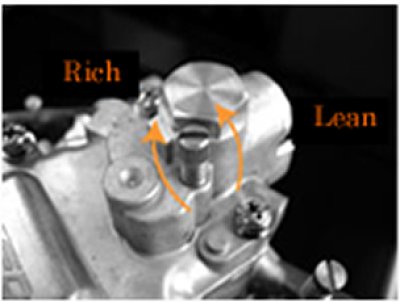
Last, I wanted to see if I had solved the bog-on-accelerate. So, I yanked on the accelerator cable at the carb and.. bog. Sadness. In my time during the rebuild, I spent more time looking at the exploded diagram than I had before. I remembered there was an accelerator circuit, and located the screw on the top of the carb. In the image on the left, here, the screw is the big one on the furthest left, near the intake-side of the carb.

When I dismantled the carb, that screw was nutted all the way down snug. So, either the prior owner had torqued it down or I did at a time I don't remember. Regardless, I started loosening that screw (lefty-loosey) while I rev'd the engine. And the bog started to fall away. I was able to rev it fairly quickly without the engine starting to die on me. I stopped loosening it before I was able to yank on the cable as if I was going from foot-off-pedal to pedal-on-floor. I believe what had been happening was that the accelerator circuit had been flooding the engine with too much fuel when I pushed on it. Now, it was getting the right amount of fuel to account for the big burst of air from the opening of the butterfly without overcompensating. Looking back, this has probably been the issue all along and the cleaning/resealing may not have been necessary. In the end, I don't care, and cleaning the carb will only pay more dividends anyway.

Wrap Up
So, did I go for a test drive? No. Why? The brake bleed attempts that I have done since I replaced the master cylinder have not gotten the brake pedal predictable. Rather than have a spirited drive to celebrate, I waited for the tailpipe to cool down and put Oliver's cover back on (queue the sad trombone). One of the first things I will be doing this spring is another brake-bleed attempt. I may just hobble over to the local Firestone and have them do it. I just want to drive this guy now and his spongey brakes have been a blocker for too long.

Also on the list are changing the 12V source for the voltage gauge from the purple circuit which used to power the clock to the switched and fused green circuit. I have a few other odds and ends I need to complete before Oliver is "finished", the largest of which is replacing the body-to-windshield seal so he can be driven in rainy weather. There is always something with these old cars and I really wouldn't want it any other way.... so long as the something doesn't leave me stranded on the side of the road outside cell range.

Well, that's it for this time. Sorry it has been so long. Life gets busy and I have not been able to play with my cars much. I am working through the permitting process to get a garage built so there will be posts about that, and then playing on cars (and blogging about it) can return to a year-round sport. Thanks for tuning back in, and I hope to be more frequent in 2025-

Tuesday, December 1, 2020

Chasing the Hapy Electrical Gremlins (part 2)

Today continues where I left off with Hapy. Last, I had pulled a cable from the rear to the front, through small openings in the frame. I wired up the accelerator pedal plug into the new cable, as well as the ignition switch. Today, we take the next few steps.

Looking Up at 40F (4C)
Yes, it is still cold. It is December, after all. Now that Thanksgiving is behind us, the holiday music can come out in full force. Meanwhile, I'm dreaming of a not-rat's-nest wiring set up. Though, I suppose, a white Christmas would be pretty great too. We start with getting the wiring up front completely tidied up. I wrapped the exposed wires from the cable with 1/2" plastic wire wrap so it remains one cable almost all the way to the ignition switch. I split off the 6 wires for the accelerator pedal from the main bundle in front of the hand brake (front is front), and wrapped that in another plastic wrap. I ran that bundle behind the accelerator pedal support down to the pedal assembly. I then fed the excess cable down through the floor, leaving a little slack in the cable, but only just a little. The work in the cab is basically done for now.

Underneath
At this point, I slid under the front end and started sending cable back towards the rear. I was only able to get about midway before the original wire clump started to become a problem. See, I reused many of the same pass-throughs that I had used 10 years ago, and pushing the cable back against these wires was really not happening. So, recognizing that the old wires are no longer needed, I removed them. Unfortunately, they were taped to the 4-wire bundle for the brake switch, so I needed to remove that bundle as well. I wasn't using that circuit anyway: it only serves to notify the ECU that the brake has been pressed so turn off cruise control. I am obviously not using cruise control, so all of those wires go. I cleared wires all the way back to the spare-tire well, and confirmed the wire colors on the accelerator pedal circuit: they match. So, while the plug changed after the 1998 New Beetle TDI implementation, the wire colors didn't. Neat.

Lower Rat Nest Tear Down
Original outlet flange
Way back when I first did the swap, I had a Vanagon rear seat heater sitting on the accessory battery tray. That heater blocked from view how bad the wiring snarl was un the engine bay. Once the heater was removed this past Summer, it could have been obvious... if I'd looked. I did at this point in this rewire, and chose to start the cleanup right there. Hidden behind the heater were the relays and other associated wiring for the coolant glow plugs. For those not in-the-know, the manual transmission TDI's delivered with an aluminum coolant outlet flange. That flange had 3 glow plugs to warm the coolant. This flange was on this engine, but the coolant outlet sticks out the wrong side. In the bus, it sticks into the fuel tank. So, I swapped it out for the plastic coolant outlet flange that routes to the sides. Anyway, all that extra wiring and relay box were just sitting there. Were. They have been removed now. I moved a couple of ground wires that were in the middle of everything and then took all of the other wiring and pushed it up through the hole into the spare tire well. The cables that remain in the engine compartment are mostly against the compartment ceiling now. I didn't do much more, because I want the wiring up above to dictate how much more I do.

Research Again
It has been 10 years since I really looked at this wiring. Fortunately, TheSamba contributor AndyBees sent me a tome of wiring knowledge back then, and since I did not meaningfully stray from his work it will very much help me now. I barely scratched the surface of this documentation when I first did this install, though I did keep it in a 3-ring binder, with the other bus books in Hapy. 10 years ago, my goal was to just get it working and then I planned to circle-back and improve / clean it up. Well, after years of wrestling with the coolant (first leaks, then overheating) and then needing a break from the bus (hence, Oliver, the 1978 MGB), I'm only now getting to this. Based on a few hours of study, I expect I will be able to significantly reduce the remaining wiring. For example, I still have relays and wiring related to the radiator fan controls, even though I have those fans on a dashboard switch. And, of course, I will not be doing cruise control. There will be other discoveries as I go.

This is as far as I've gotten. My next steps are to start eliminating wiring related to functionality I am not going to retain (cruise control, etc). Since Hapy is outside/carported, this may take a while as I wait for nicer (read: warmer) days. We usually get a 50F/10C-degree day here and there. Since Hapy is blocking the garage bay where Oliver is parked, I may get my wrenching fix with some little projects on him when the weather is too cold to play with Hapy. Time, or more like weather, will tell. Thanks, as always for following along. Please stay isolated, and wear your mask / wash your hands when you can't.

Tuesday, November 24, 2020

Chasing the Hapy Electrical Gremlins (part 1)

In the Summer of 2019, we barely made it home at the end of the Dog Days 333 (See parts 1 and 2). Hapy decided to just not start on command anymore. He was dropping into that modified limp mode and it was happening not just when he was cold, but pretty much at random. I promised him that I would fix it as we sat idling in a Dundee convenience store parking lot while C was in getting us drinks. Today's post starts that "fix it" journey. Before I begin, for my US readers, Hapy ThxGiving. For CoViD's sake, please stay home.

One Last Time
Hapy parked in tarmac spot
Hapy's usual home
After I finished the priming of all the Zed body panels (See Zed Prime), I moved them into the garage. This freed a covered one-car parking space. I had initially planned to put Nemo back in there and get after his wheel bearings. I decided instead that with the CoViD-19 numbers climbing to all-time highs, maybe it was okay if I didn't have a car that could take me too terribly far. Nemo can get me to the corner store and back; that's plenty until I can get the wheel bearings done.. once I confirm that they are the source of the noise, and it isn't just loud tires. So, I switched it up, and I am instead jumping into the Hapy electrical. I could have gone after this stuff at any point during the nice warm summer. That just wouldn't have been consistent with all the other work that's been done on this beast, so of course instead I chose some of the coldest days this year to do it.

First, I had to get Hapy into the spot. He is usually parked on a tarmac strip at the curve of our driveway so we can see him out our bedroom window. Yeah, we're weird. For any other car, moving it would be a simple effort of start, drive forward, reverse into the spot. Once I got the other cars out of the way, it was his turn, and just like so many times before, he just didn't want to start. I turned the key to start and nothing happened. Sigh. So, I tried to push him. Nope. There's a little dip in the tarmac that he would roll back into. I had to pull him onto the concrete with a trucker's chain around his front sway bar at one end (his front tow hook was pancaked by the prior owner) and around Nemo's front end on the other end. Fun. While I was trying to figure out how I was going to push him back into the covered spot, I lamented out loud to Hapy "why can't you just start one more time?". His response: he started. Of course; good boy. So, I backed him into the covered spot, and turned off the key.

Running Cable
In the TDI retrospective about secondary electrical, I mentioned replacing the single wires I originally installed 10 years ago with a cable. Well, I bought 30 feet (~10m) of 12-wire 16ga cable for this job when I bought cable for the additional gauge (see Oil Pressure and Temperature Part 4). It is not quite as thick as my ring finger as a sealed cable, and it has a nice thick jacket on it. I figured that the computer and rat's nest wiring is on the driver (left) side, as are the accelerator pedal and ignition switch. So, running the cable along the driver side made more sense than running it along the other side. Turned out, I thought the same thing 10 years ago, as the old wire bundle ran that way. I started from the rear, threading the cable through the bottom of the spare tire well and down into the engine compartment. From there, I ran it through manufactured holes in the frame over the rear suspension, along the inside of the mid-section frame rail to the cross member near the new heater location. I pressed the cable through a square hole in the cross-member, under the brake booster and then through another square hole into the area covered by the front belly pan. I had bored a large (~1/2 inch diameter) hole at the very front over the Summer when I routed the heater fan control cable through. I had planned to reuse that hole for this cable, and it fit with very little trouble. I pushed and pulled about 5 feet of cable up through that hole so I could stand alongside the driver seat to do the wiring bits.

Wire Front First
The 12-wire bundle is more than I was really ready for. The accelerator pedal needs 6 of them. The start and run signals account for 2 more and the OBDII signal is the last. The other wires will be used in the future for things like a speed sensor and a glow plug light. Like the extra wire in the cable I strung for the oil temp and pressure for a low coolant warning, I'll get to those later. For posterity (and my own personal reference later), these are the circuits for the 12-wire cable. I will update this as I make changes or discover mistakes:

circuit wire color purpose
1 Red Accelerator Pedal 1
2 Yellow
Accelerator Pedal 2
3 Orange Accelerator Pedal 3
4 Brown Accelerator Pedal 4
5 Blue Accelerator Pedal 5
6 Black Accelerator Pedal 6
7 Red/Black Ignition - START
8 Blue/Black Speed Sensor
9 Orange/Black OBD-II
10 Yellow/Black Ignition - RUN
11 Brown/Black Glow Plug signal
12 Black/Red OPEN

I started with the ignition, splicing into the existing "RUN" circuit with the new signal wire. I figure the existing stuff (like lights) need power too, so the existing wire will simply feed old circuit #15. For the "START" signal, I just ran the new wire. The old starter signal was pretty batty, but it proved the TDI install was viable. Recall, it ran from the ignition down the old wire to right near the starter where it was spliced into a new wire that ran around the engine compartment to the spare tire hole through a relay to the computer, which then signaled TDI-donor relay to fire the starter... thru a new wire to the starter solenoid. There's like 20' (7m) of excessive and old wiring that I can eliminate. Then, I moved to the accelerator pedal.

Now, recall that I had to swap out the original round-plug accelerator pedal plug with a newer-model flat one after the old fly-by-wire pedal started to short out. I took a picture to help me identify which wire is which at the other end, but because the plug was changed, I expect the wire colors were as well, so when I cut the old wires off, I left about 1/2 inch of flat-plug wire on there so I can compare with the picture (here on the right) when I get to the rear-end wiring.

EDIT: I have updated the picture on the right here and the wiring reference above to reflect the actual circuit numbers in the wiring diagrams to avoid any confusion. Originally, the numbers ran the wrong direction relative to the official wiring schematics.

Even without the change, it was important to consider placement of the cable and the things that were going to be wired into it when I made my cuts to the wires. The ignition, speed sensor, etc are all at the dash where the accelerator is at the right foot. I made sure there was about 3 feet (1m) of cable between the ignition and the accelerator pedal cuts so there is room for cable routing. Also, it was important to pre-route the cable as much as I could so we didn't end up with the cable running in front of the steering column or goofy some other way.

Next
I admit, that doesn't sound like much. I moved the bus, ran some cable and did the wiring at the front end. Still, in sub 40*F (4C) it was a feat getting that much done without going numb. The weather around here is decidedly cold. I accept that I will not be able to get things done on Hapy very quickly, but with him out of the rain, at least it is not completely miserable. Just cold. If I can stand the cold, I will finish up the wire cable in the front by wrapping it with some plastic wrap, and pressing the excess cable back into the belly pan. Then, I'll push/pull the excess back to the rear so I have room to wire up the controls back there, probably leaving me close to 3m of leftover cable. There is a great deal of electrical housekeeping that I have not done back there. I think this is the right time to clean all that up, removing the unnecessary, trimming and mounting, etc so it is nice and clean. And, or course, our sporadic modified limp mode will no longer appear. It's all about staying warm enough to take small steps forward and eventually the wiring will be done. Then, I'll switch to diagnosing Nemo's rear bearings again.

Thanks, as always, for following along. Posts may appear more slowly as my work slows down. I'm still working on it (and staying CoViD safe, of course).

Tuesday, January 14, 2020

TDI install retrospective: Secondary Electrical

Continuing the process of back-documenting what I did to put a TDI engine into an old (1972) air-cooled VW bus. Today I cover what I call the "secondary electrical". This includes everything that isn't responsible for the alternator:battery:starter system. So, this is the radiator fans, the accelerator pedal, the OBD-II plug by the driver seat and any other miscellaneous stuff I can think of.

This is the first post following the announcement of Neil Peart's death, and I can't let it pass without expressing my heart-felt loss. I love Rush and wish Getty and Alex my deepest condolences. With 2112 blasting in my ears, and "with hungry mind and open eyes"... we return to the TDI retrospective.

Random Cables
Beyond the core primary cables, there are a few thicker wires that need to be run between the relay bank and the battery-top fuses. For these, I found wire of the same thickness, and ran them through the hole in the spare tire well, along the top of the rear engine hatch to the battery-top fuse box. This pathway became fairly well used for sending wiring from the computer to the sensors and senders around the engine. To enable that, I expanded the hole from a tiny drip opening to a 1 inch by 2 inch rectangle.

Cooling Fans Circuit
old NB pedal on left, brake switch on right
I had originally tried to re-use the TDI-stock thick relay and control module to control the radiator fans. That was a mess, and didn't work, so I ripped it all out. Instead, I used one of the small battery-top fused circuits for a power source and a switch on the dash to trigger the fans. The switch went into a hole in the metal dashboard that had not been exposed through the vinyl cover, right next to the ashtray. It receives power from an always-on source so I can cool the radiator even when the engine is off. It triggers a standard relay mounted next to the radiator on the passenger side. When triggered, the 12V from the battery-top fused circuit sends 12V to the radiator fans and the little fan on the inter-cooler. This is a simple circuit, but I have found that long bumpy road trips cause the clips to slowly shake off the relay. So, I may need to put a dab of threadlock on there to stop that.

Accelerator Pedal
new pedal
I originally used the accelerator pedal from the NewBeetle (NB). This was a one-year-only part, so when it eventually failed I had to either pay a few hundred dollars for a replacement or swap it out for the more common pedal. The challenge with the more common pedal was that the rheostat was integrated into the pedal body, so I couldn't hide it like I had hidden the NB pedal. The NB pedal had been stowed inside the belly pan, and allowed me to continue to use the original bus pedal. The integrated housing style pedal meant that the entire pedal would be changed, and it would need a support. I still don't like the final look, but it places the pedal in the right spot for my foot, and it drives correctly. The wiring was fairly easy. There are 6 wires attached to a flat pigtail. I extended the wires and ran the 6-wire bundle under the bus from front-to-back, arriving in the spare tire well, and wired into the computer where the pedal originally wired in. I believe I used wires that were just a bit too thin, because I get sporadic limp-mode issues from lack of signal from the accelerator pedal. See Pedal on the Right for details on the install.

Brake Pedal
NOT USED. If you intend to use cruise control, the computer needs to know when the brake pedal has been depressed. I thought about tying into the brake warning system or putting the sensor on the master cylinder. Ultimately, I made a little bracket on the arm of the brake pedal and the switch triggers when I step on the brake. I don't use cruise control, so I've kind of forgotten about this pedal. 10 years later, this may not work at all, so be advised, this may not be a viable solution. You can see a picture of my switch above. No, it isn't pretty, but at the time it was functional.

Fuel Level
NOT DONE. The range of allowed values for the fuel level gauge in the bus is quite different from the range for the TDI. If you want to swap out the original sender, I found one that would work at Summit Racing. I had thought about building a circuit which would translate the reading on the stock sender into the range accepted by the TDI computer, but I shifted onto other things. My thought was that the original gauge could still work, or I could reference what the computer thinks. I may still do this, or just buy something that does it, like the SN34 from Classic Instruments. For now, I am using the stock level sender and gauge; the computer has no idea how much fuel we have. Most of the time, I don't either.

Speed Sensor
NOT DONE. There are a few ways to go after this. I started down a few paths and decided that I didn't need for the computer to know how fast I was going, so I stopped working on it. My first stop was to try to adapt the vehicle speed sensor (VSS) from the TDI. I couldn't figure that out. So, then I looked into getting something that fit between the dash and the speedometer cable. This looks especially promising as there is a company in Britain (RJ Engineered Solutions, VSS link here) that makes a thread-in plug that fits into the back of the speedometer that the cable threads into. It produces a square wave the computer can understand. While writing this post, I ordered one so I could complete the experiment later. I'll post about my findings once I have some. Since I first investigated this, there are more plug-in options (like Dakota Digital), so you may find something that better suits your project than the RJES solution. The last option is to build your own Hall Effect (or other) sensor. Whichever way you go, Dakota Digital also offers a small magic box (SGI-5E Universal Signal Interface Unit) that can adjust the signal from the sensor to the ECU so you can account for a signal mismatch or simply because you got bigger tires... like I did.

OBD-II
UltraGauge
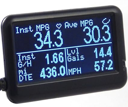
Since I decided against retrofitting the Beetle dash-pod into the dash of the bus, I still needed some engine monitoring. The old bus had 2 lights for monitoring: one to tell you you're out of oil so your engine is toasted and the other to tell you your electrical is shot. Ultimately, your warning system is your ears. Good thing the radio is so lousy, or not there, so you can hear the clamor from the engine bay. That model doesn't work for the TDI: you can't hear a coolant leak or overheating, and by the time you hear the result of the failure, it's too late. So, I extended the signal wire from the OBD-II plug from the rear of the bus to the front by the gearshift. I got a generic OBD-II plug off eBay (it's new, I just avoid Azn) that only had 3 wires: 12V power, ground and signal. The first 2 were easy, wired the 12V to a switched circuit (15) and grounded against the dash. For the signal, I traced the signal wire on the generic and determined which wire from the stock plug matched it. I know that sounds improbable, but it totally worked. Back then, there weren't the BlueTooth OBD-II readers around today. I got a wired one (UltraGauge) for around $80US that's about 1.5 inches tall and maybe 2.5 inches wide that I have jammed into the corner where the dash meets the driver-side A-pillar. I set the screen to show me engine temp and RPM's so I can watch the 2 things I care most about. I love/hate that thing. The longer I go without a coolant temperature issue, the more I realize just how much that $80 gadget saved my engine.

Along the way, I got a ScanTool OBDLink LX thinking I would integrate a more sophisticated graphical dashboard. It is pretty clever, and with a small tablet, a fuller engine monitoring capability is there for the taking. For me, it doesn't make sense until I have the fuel level and speed getting sent to the computer, so the tablet dash will wait.

Heater Fan
I had heat, but when I had my ignition fire, I removed the electrical parts to reduce the load on the circuits up front. If you intend to wire fans for heat, I suggest you find a strong source of 12V power and use an isolated circuit for it. I would just check the power draw for your fans and plan accordingly. You don't want to blow an important fuse because you kicked the fans onto high. I know I will be doing something to restore a defroster at least. I will probably source power from the battery-top fuses rather than the original bus fuse box and then use a new switch rather than the original Vanagon rear-seat heater switch. Because I already have it in-hand, I will probably re-use the Vanagon rear-seat heater unit, though. I'll just need to figure out where to locate it closer to the front of the bus without appearing in the passenger compartment.

Un-Rat-Nest Wiring
I have done this a few times and still need to do more. Unlike all of the other things on this project, this one is most like cleaning your shop or going to the dentist: you never feel like it, but you're so grateful you did afterwards. The original harnesses are not length-appropriate for this application. Along the way, we extended the ones we needed to extend. This step is about shortening all the others so you don't have a big old rat's nest of wire. I have sourced a relay block to re-route all of the relays, and I will be mounting the TDI fusebox as well as tidying up the wiring so it looks like it was all done on purpose. As of now, however, I have only removed the extra wires that were not needed.

There are quite a few wires running from the engine or computer to the front of the bus, but they can be isolated into clumps based on purpose. Accelerator pedal (6), brake pedal (2), ignition (2), OBD-II (1) and the fan switch (1)... so 12 wires. All of them are relatively thin, like 18ga or smaller, because they just send signals, and don't push power. Arguably, all of them could run through one cable of multi-colored wires (like this). If I were to start from scratch, that's probably how I would do it. In fact, I may re-do it anyway and eliminate the occasional signal loss from the accelerator pedal to ECU. If you include the speed sensor and fuel level sender, you will need more than 12 wires, so maybe something like this instead.

Prior related posts:
Preparation
Fuel System
Physical Mounting
Vacuum System
Air, Inter-cooler and Exhaust
Primary Electrical
Cooling

Next related posts:
ECU, dashpod and Sensors

Tuesday, April 1, 2014

Thinking while Dinking

I unexpectedly had Sunday available to putter on the bus.  Boo was supposed to work, but suddenly didn't have a shift.  So, after a visit to the gym (I really need to do that more), I opened the garage door, turned on some tunes and pondered the bus.  Sometimes, you need to just be with your project to have an epiphany.  I had a flash of brilliance that (hopefully) could solve the wet-weather challenges for good.

Cutting Cards
I decided that a free afternoon shouldn't count in my build versus buy math since the afternoon was free.  So, I pulled out the Dremel and cut another door card.  Okay, back up.  First, I took the first door card I did and started trying to hang it on the passenger door.  I found little things that needed to get adjusted.  The grab handle holes weren't big enough.  Then the inner latch surround thing didn't fit.  Last, I realized that the holes for the door clips weren't there.  That was kinda fun, actually.  I took the ratty old door card and laid it on top of the new one.  I set those on top of a fresh piece of MDF.  Once lined up, I grabbed my drill with a 3/8" bit and bored straight through the door clip holes in the ratty door card into the new one and the MDF underneath.  Perfect.  I pulled the ratty card off the stack and traced the other holes and around the edge.  30 minutes with the Dremel later, I had a duplicate of the new card.

I still need to do a little sanding around the edges to make it a really nice fit.  The holes line up well and the grab handle, window winder and inner latch all mount correctly now.  Its just a little 100%-ing around the edges.

Hanging the Plastic Curtain
Originally, the early VW's had a "vapor barrier" between the door card and the steel door.  This was because no matter how good your seals were, water would seep inside the door, and could slowly rot the MDF/cardboard cards.  Most VW's have had these plastic sheets ripped out by stereo installers or confused mechanics, and their door cards have accordingly suffered.  I have tried a few different things over the years to get a plastic sheet to stay in place, but spray adhesives, contact cement and gorilla glue don't work.  Or they work too well.  Ultimately, I've just driven around without door cards while waiting for the answer to appear.  I found a posting on a website where a guy used that blue poster tack stuff (called BlueTac), and said it worked great.  I'll be trying it myself: a thin line of that sticky stuff all along the edge, taking care to avoid the door card mounting holes.  It occurred to me that this might be the solution I've been looking for with the belly pan too.

The belly pan, if you don't remember, is really a mechanical protection against rocks and such.  I've been trying to also use it as a splash-guard to keep the pedal electronics dry.  I'm going to try using the BlueTac solution with a sheet of plastic.  Figure, if I can protect a door card, I should be able to protect the electronics the same way: simple sheet of plastic held in-place with BlueTac.  I should also be able to cover the uppers, making the small sub-floor water-safe.  Neat.

That's it for today.  I bought some 3M-verson of BlueTac at Office Depot yesterday so I'll try the plastic thing this week.  Until then, here's another picture from the door card development effort.
3/8" drill bit fits perfectly in the mounting holes

Wednesday, May 23, 2012

Zoom zoom

It seems that I've been gone long enough for the blogger format to have changed.  Apologies to my regular readers for both my delay and for any weirdness caused by the new blogger interface.  It'll be a basic update today, just touching on bus stuff.

Daily Driving
The ol' bus and I have been a tight-pair the last few weeks.  I've been driving him to work and back pretty much every day.  I've noticed a few things that are curious, but not necessarily alarming.  First, the coolant level continues to drop, but I can't spot a leak.  Also, the pressure (or is it vacuum?) build-up is so pure and strong that after a drive the coolant bottle is nearly empty.  When I remove the cap of the fill-bottle, coolant splashes back in all the way to the full line.  Crazy.  So, I hear the low-coolant alarm in the donor dash, but it doesn't necessarily mean I'm low on coolant... I really over-filled the bottle this morning.  I'll post what happens.
Second, there's an oil leak.  I don't know where it is, but the bus definitely leaves his mark when I park him. I think the oil line to or from the turbo could be it, or its the oil cooler or maybe the underside of the oil filter housing.  Regardless, I'll find a dry day next weekend and tighten everything.  I was just under there last weekend re-tightening all the coolant line hose clamps.  There's always something, but that's part of owning a 40 year old car.

Acceleration Interruption
fixed and re-installing
On the way home from work on Friday May 11th, I had a breakdown in the left-hand progress (not turn) lane during rush-hour.  The accelerator suddenly dropped to the floor and I was rolling without throttle control.  The RPM's dropped to 900, so I quickly scanned the traffic on Hall Blvd (in Beaverton).  I was unable to slide right, so I took a left turn into an apartment complex parking lot through the oncoming traffic.  Sketch.  I removed the front belly pan and discovered that my hack-awful welding job on the accelerator resistor bracket (see Accelerating Slowly) had failed.  Dandy.  With my welder deep in storage, getting this fixed could have been a real time killer.  Fortunately, Boo has a local mechanic guy (Johnny) who can do small welding repairs, so I asked him to do it.  Less than an hour (and only $15) after I gave it to him, the weld was done and the whole thing was painted.  I can''t find a business name for Johnny's garage, but the location is (9085 SW Beaverton Hillsdale Highway, Beaverton, Oregon).  Great guy.  Talk your ear-off, if you let him, but he'll fix your car for a fair price.

Since I've neglected the blog a bit, I'll post again in a couple of days covering snow and personal experiences.... and, of course, another bus conundrum. :)  As always, thanks for following along, and another apology for my blog negligence.

Saturday, March 31, 2012

Moving and Moving

Has it really been a month since I last posted?  Apparently so.  Its been a hectic March, so I apologize for the radio silence.  Its still crazy, so this will be brief, but should get you all caught up too.  Lots of work stuff has been going on, but I won't bore you with those details.  Let's just say I've been at work a lot.

Moving
First, my landlord chose to increase my rent by $80/month when my lease renew was up.  Seeing how my income is year-based, there's little I can do to bridge that gap other than cut spending elsewhere.  I'm already kinda near the bone spending-wise, so I decided to counter their proposal with a move-out.  This is where things get a little interesting.  I thought I had until the end of April, but it turns out the lease was through the 11th, so I had to get crackin' on finding another place to live, packing up stuff, and moving.  I have all that resolved temporarily, but I'm still vacating the old apartment.  In fact, I've used the bus for a large bulk of the transportation.

Water tight?
In my last post, I talked about getting the little clip on from the bottom to get the cooling system to seal.  That was the ticket, it turns out.  After multiple trips over the last week or so, he hasn't dripped a drop of water.  Oil, on the other hand, he continues to spread in little drips.  I'll solve that later.  Before I could really use the bus to help haul stuff, I had to make sure he was water-ready.  For those of you not in the US Pacific NorthWest, you may not know just how wet it is here right now.  We have had rain almost every day since my last post.  With standing and moving water on the streets, parking lots and just about everywhere else, I needed to be sure the bus could keep going if I hit some.

So, the weekend I gave notice, I slid under the bus and did some less-than-permanent adjustments to some wiring.  The radiator fan related wires all trigger off of a relay.  That relay is now wrapped in plastic wrap.  I know, that sounds positively awful, but it works, and the relay has stayed dry through this weather.

Next, I removed the belly pan from under the cab.  After a good cleaning, I covered the inside with vibration noise reducing sheets.  This should reduce a little road noise as well as seal off the small drain hole.  I then caulked the front and sides of the pan and re-attached it.  I know that if I hit a big enough puddle, water could come over the top of the support members, but that's a problem to be solved later too.  For now, I'll avoid large puddles at speed.  I didn't seal the back, thinking that any little bit of water that got in would need a way out.  So far, the caulk and hole patch work very well: electronic accelerator and brake pedal switch have been working perfectly.

And Moving
After the minor water-proofish modifications, the bus was ready.  I have driven him to and from a storage facility as well as to/from another apartment nearly every day for the last 2 weeks.  He has started right up, driven with pep and carried every burden I put inside without issue.  I have 2 or three large items left and then the usual debris that needs to be resolved, but my move is about complete.  The bus has been a great way to move in a steady downpour, keeping my stuff dry without tarps.

I need to figure out how I can park both my daily driver and the bus at the new place, though.  Unlike the old place, I don't have a 2-car garage.  So, I'll annoy my neighbors for a while as I resolve this.  As I mentioned earlier, this is a temporary housing solution, so I'll be moving again pretty soon.

That's it for today.  I've avoided my moving tasks for long enough this morning, and need to get back at it.  Today, I'll be completing the packing of the garage, and moving those big items I mentioned.  That will leave the final sweep for stuff, a trash run and then the final cleaning.  Moving is such fun...
 

Monday, January 10, 2011

running again

Ok, so it's halftime during the college football national championship game, so this will be brief. My friend Justin stopped over on Sunday afternoon, and we got the engine running again. For the second time, we needed to fake the clutch pedal switch. The jumper we did before either fell out or I knocked it out. Regardless, once we jumpered that switch, the starter would engage again.

Fuel System Alteration
we removed the one-way valve from the fuel feed line, believing it was restricting the fuel flow. I'm still concerned that we won't get sufficient prime after sitting overnight, but I'll be able to test that theory tomorrow night. In its place, we put a Mercedes secondary (clear) filter. We should be able to see if there is prime in the fuel line just by looking at that.

Battery suck-eth
The battery I nabbed from the old Mercedes was pretty much drained by the time we got to being able to test-fire, it wasn't able to turn the engine. We tried the Harbor Freight battery charger/jumper, but that didn't have the juice. Then, we charged the battery a bit, tried again... no avail. Finally, charging through jumpers running off of Justin's Golf was the winner. Regardless, the engine is running again, and the battery is sitting on the slow-charge. I'll fire that engine up again to drive to the muffler shop hopefully this week.

Justin's Discoveries
In looking at and poking at the engine, Justin noticed a few things. Some items, we were able to fix on the spot, like a loose fuel pressure sensor on the IP, but others may need future attention. The VNT actuator was not responding very well. We think that may self-correct just from use - remember the engine has only run a handful of times in the past 3 years. While we were banging away, Justin re-checked my accelerator switch, and it runs from 0% to 77% now. I need to extend the throw of the pedal somehow, but that can wait. Also, he verified the IP timing, and the flow of the injectors - all good. We're ready for test flights.

That's it for tonight. The game is coming back on. If we don't get snow, I'll be taking a test flight tomorrow night. I hope to get into the Meineke shop around the corner between Wednesday and Friday so I'm road-able. Then, it is just a matter of increased length test fights, minor tweaks and cosmetics. Unbelievable. As an Oregonian, I say "Go DUCKS".

Wednesday, August 11, 2010

Code Free

My friend (and TDI Mechanical Guru) Justin visited last night, and we made some progress on the VAG-COM codes. We had a minor discovery with the accelerator pedal controller as well, but overall, it was a very positive few hours. That "red ball" project has moved on, and work has settled a bit. We'll see how long that lasts....

Code Free
Justin arrived before I got home from work, ready to get the bus running. He confirmed that seeing the mileage on the dashpod was a significant step, and was able to get his VAG-COM reading application on his laptop to communicate with the engine computer. He brought a 99.5 Jetta harness with him - the complete harness for the entire car. We picked through the harness and noted a single 2-plug connector that hooked the smaller engine harness with the other engine-ish harness. Connecting this did not relieve any codes, but it reminded us of the research I mentioned in the last post about all of the codes appearing on elements contained within that same harness. We took his 99.5 harness and hooked it into my engine, leaving the glow-plugs disconnected, to test this theory. VAG-COM was unable to find any error codes / faults. For the time being, I'll be leaving the 99.5 harness in-place and removing my 98 harness. I'll find the bad connectivity wire and fix it off-line. Meanwhile, this resolution brought us to the edge of being able to start the engine.

Clutch Pedal switch
For some reason that I really don't understand, VW included a switch on the clutch pedal to prevent anyone from being able to start their car with the clutch out. I suppose there were complaints about this, or maybe this is one of those Ralph Nader safety things, but I think its pretty stupid. Accidentally trying to start it in gear has its own notification system: that uncomfortable lurch followed by not starting. Anyway, this switch needs to be depressed to allow the starter to get the signal to start. In the early TDI (ALH model), the switch runs through the comfort system, which I tore out. The only signal that matters, though, is a single signal from that system to the #3 relay (number 185 printed on the top) which is the starter lockout relay. That relay takes start-switched power (50b) and routes it to the starter solenoid when 12V are applied to the relay switch from the comfort system wire. Since the send-side of the relay only has 12V when the ignition is turned to "start", the relay, the comfort system, and the clutch pedal switch are not needed... in my application. We jumpered across the relay, and got around the clutch switch problem.

Still NOT Starter-ing
After we got around the clutch pedal switch, the starter still wouldn't turn. To rule out a bad starter, we sent a test wire directly from the solenoid to the battery and proved that the motor turned. Unfortunately, we discovered that the spacer that I introduced between the adapter and the starter caused the teeth on the starter to fail to reach the flywheel. I will be removing the starter, removing the spacer and re-installing the starter. Figure 30 minutes, but unfortunate that it stood in the way. Also, this indicated that the wire running from the relay to the starter solenoid had a break in it. I will need to cut up the wiring zip-ties and find the continuity break. Since there are 2 splices, it shouldn't take long to find which splice failed.

Throttled
Our last discovery was that the direct connection of the bus accelerator pedal to the throttle switch was pre-loading the throttle signal. This means that even without a foot on the pedal, the computer thought we were trying to be at about 35% (not 0%). This is because the old pedal needs some kind of pull from the old carburetor to keep the pedal upright. I will add some space between the throttle switch and the pedal and add a return spring to provide that pressure. That shouldn't take me very long, once I find a return spring.

That's it for today. There was a lot of progress, and the outlook is very bright. I won't be able to put much time in over the next few weeks for travel reasons, but I know what I have in front of me. First, fix the starter signal, R&R the starter and prove the starter can turn the motor. Then, fix the accelerator pedal bit. Once I have that, I'll re-focus on the air cleaner (AMSOIL) and air-source for the vacuum and then look for the break in the engine harness so I can give Justin's back to him. As always, thanks for following along and enjoy the rest of your summer-

TDI-FEST: Portland, OR Labor Day Weekend

Sunday, April 11, 2010

Accelerating, slowly

I haven't been able to do anything on the bus these last couple of weeks. The project that I'm working on is nearing the end of its development cycle so we're working lots of evenings and weekends to get it tight. Basically, I've worked some every day since I've gotten back from Mt. Bachelor. Good times. Better to be getting worked too hard than not have work at all, though. Anyway, I did get a few hours yesterday, so I focused again on the electrical. I'll flap about the accelerator pedal today.

Inside Electrical
The morning started cold, with a stiff wind. After gearing up, and mentally psyching myself, I got the bus uncovered and climbed inside. I re-connected the westy electrical stuff that I had pulled out last Fall when I was looking at putting the fuel tank under the rock-n-roll bed. I discovered that the wood box thing that covers the power inverter was never physically attached to the seat frame. Huh. Now it is. I then pondered the impacts of trying to remove the fridge unit.
I had planned to remove the fridge, since I don't use it anyway, and put the harness in there. Then, I was going to build a false-bottom with a piece of plywood and use the cabinet as dry-good storage. Sounds great, eh? The problem is, that would take the better part of a day to do, and I don't have that kind of time anymore. So... that becomes another punt-it-to-Fall item. Instead, I'll be running the main harness through to that cabinet and then under the rock-n-roll bed. I'll lose a little storage for the Summer, but it will take far less time to get good-enough-for-now.

Accelerating
The TDI engine, like most modern marvel engines, is controlled more by the computer than it is by your foot. Sure, when you step on the "gas", you speed up, but gone are the days of stomping on it and producing a big cloud of exhaust smoke as you rocket forward. Okay... that never actually happened in a microbus, but if you drove one of those carbureted cars of yester-year, you know what I'm talking about. Anyway, the modern cars have a rheostat (variable resistor like a dimmer for your fancy house lights) connected to the pedal, and that sends a signal to your computer to tell the engine to go faster. Now, the computer is smart enough to know that you can't just throw gas into the engine like a monkey sitting atop it with a bucket. The computer figures out how to get to your intended velocity without wasting fuel, so you take off like a rocket, but no cloud of smoke. I can't really imagine that kind of force in a bus, but I should after this. Anyway...

Think, then Act
Before Christmas, Hal and I spent some mental cycles on this issue. After cutting the accelerator rheostat from the donor housing, we slid under the bus an figured that the dangle that used to connect to the old pedal could connect directly to the "V"-shaped bracket on the bus pedal that used to pull on the cable back to the old carb. All we needed was some time, a bar of steel, and some care. I put those 3 requirements together on Saturday, and fab'd the bracket. I'm the first to admit that my welding skills are just crap, but after messing around with is for a while, I got this so it will hold no matter how much pull pressure I put on the rheostat. As you can see, the rheostat housing is not in a perfect line. That was done on purpose. The "V" on the accelerator needs to travel in a straight line, but the bracket couldn't fit directly under the pedal. So, it is attached on an angle. I drilled 1/4" holes in the bar before welding so I could fit it around the accelerator pedal bolts. The one closest to the rheostat housing is for one of those screws to slide through. This helped with placement.

Mount Accelerator
Once the bracket was constructed, install was a relatively simple matter. The bracket slid right over the pedal mounting screw and I marked the 2 mounting holes by scraping the paint underneath. Unfortunately, these 2 holes were almost directly above the steering mechanism, so I had to punch pilot holes from below and drill them from above. The picture to the right here shows where those 2 holes were made relative to the bottom of the pedal. I slid the bolts through fender washers from above. Then, the bracket slid right on to the 1 screw and 2 bolts. I thumb tightened them, and with the use of vice-grips, got the bracket in.

Set Motion
Once the bracket was mounted to the underside of the bus, I had to verify the range of motion of the pedal relative to the motion of the rheostat. Up until now, I had the accelerator pedal pulled up with a loose bungy cord. Now, it was time to connect the bits. By retaining the original housing, I was able to take advantage of the original adjustability - it has an allen bolt on either side. It was a relatively simple matter of loosening the bolts, and trying the action until I was able to get the accelerator to go to the floor for full throttle and 3-4 inches off the floor for at-rest. The range of motion for the bus pedal will now be less than it used to be, but there is no standing resistance / pressure on the rheostat until a foot is placed on the pedal. The picture to the left, here, shows the pedal after it has been completely installed. It is important to note that this section of the underside is covered with a belly pan. I will be putting in a seal to keep water out, so this should be a safe location for it. If you are thinking of doing this, consider whether you like to ford streams before jumping in. If this resistor gets wet repeatedly, it will fail, and you'll have to replace it.

That's it for today. I'm working again today (waiting on a job to complete now, actually), so I probably won't be getting into the bus much today. The weather is perfect for working outside, so it really pains me to say that. I am growing increasingly concerned about my time line. If this work level keeps up, I won't hit my dates, and I won't be camping in the bus this Summer.

Pictures:
top left - my awful welding of the accelerator housing to the steel bar.
top right - the bracket from the other side
middle - mounting holes in the floor. note the base of the accelerator pedal barely visible
bottom - accelerator pedal control switch (rheostat) in place