Showing posts with label steering. Show all posts

Tuesday, September 14, 2021

Handling the Handling (Shock Adjustment)

In my post about the drive to and from 4Peaks in August (See 4Peaks 2021 - Road Report), I mentioned the impact of the wind on the handling of the bus. Today's post covers my initial attempt to address it. I say "initial" because I have not 100% confirmed this is the end-all solution to the issue.

Identify Causes
It makes sense to start with what the possible causes could be for the wind to have such a dramatic, and newly so dramatic, impact. I have thought about this quite a bit, mostly while driving Hapy, and I have come to the conclusion that the root cause is one of 2 things.

My first thought is around a change I made to the bus. Back in Spring, I added a tow hitch. No big deal there, with regards to wind, but I think it looks really good (See Bus Tow Hitch). Starting with the trip to Leisureland I added one of those carrier platform things from Harbor Freight that go into the square trailer hitch thing. I also got the zippered bag that fits it and refer to the pair as "the Boot". I don't put much in the Boot, but it creates lots of room inside the bus... and it creates this little .6m (2 foot) high by .5m deep waggy-tail sticking out the back. I thought, with the loaf-of-bread broadside, that this addition would not have an impact. I could be wrong. If that is the cause, I would still like to keep using it so I need to improve the handling to compensate.

My next thought is around the adjustable Koni oil-filled shocks I installed years ago. I was part of the first group purchase that triggered Koni to start manufacturing them again. I didn't write that for kudos, rather to illustrate how long I have had them. That purchase was, like, 15 years ago. I didn't do anything with them other than pull them out of the box and install them. Now, so many years later, I realize that out-of-the-box they are set at their softest setting (face-palm). That setting might be great for an unloaded bus tooling around town, and when the shocks were new, maybe they even had a little stiffness in them as they broke in. Well, it's been many years and while I haven't driven Hapy around much (less than 20k miles total since I bought Hapy almost 20 years ago), the last few years would have definitely gotten them past the break-in period if he wasn't past it already. With all the camping gear, plus the Boot, I am asking much more of those shocks than when I used an empty Hapy to get to/from work back when I first installed them.

So, I figured I can start with stiffening the shocks.

Adjust Shocks
Koni 80-series shock
The 80-series Koni shocks were designed to be easily adjusted. Of course, I neglected to do anything with them after install. After doing some reading, I have found others with a similar vintage bus and similar need: better handling when loaded for camping. The consensus is to stiffen the ride. The lack of consensus is by how much. Because of the extra tail created by the Boot, I did a full turn in the rear and a 1/2 turn in the front. I expect, that with the heavy duty 7/8" anti-roll (sway) bar in the front, even the 1/2 turn is more than I need, but I would rather feel the bumps a little more and have the bus hold steady than the alternative. Shout out to RAtwell for his page on these shocks. It's an older page, and hasn't been updated in a while, but there is some great, still relevant, information in there.

Adjustment is relatively simple. The videos from Koni show the shocks uninstalled, and some of the verbiage seems to say opposing things. I don't want to remove the shock entirely from the bus to adjust them anyway, and I don't think anyone else does either. So, I did it like this:

Rear's first. With the bus on the ground, just crack both the top and bottom bolts enough to remove any torque (19mm). It may be too difficult to get to the top one, and it may not be 100% necessary. I didn't loosen the top bolt on the driver side, and it wasn't an issue. Regardless, completely remove the bolt from the bottom. Notice that there is a nut on the other side (wheel side) that requires a 17mm wrench while you work the ratchet from the inside. With both hands, push the lower end of the shock (you have them installed with the thicker section on top like the picture above/right, right?) up into the upper section. When you are just about bottomed out, start rotating the end of the shock you're holding a little bit. You are looking for a click to tell you that the adjuster has engaged. When you feel that click, you are ready to adjust ad you can completely bottom out the shock (but do it gently). I did not feel the click on all 4 shocks, but once fully compressed, I could only rotate the shock 2 full turns, so some (older) models may not have that satisfying click.

original image
from RAtwell.com
From below, rotating it clockwise will stiffen the rebound of the shock. Rotating it anti-clockwise will soften the rebound. That is the only adjustment you can make on these red 80-series oil-filled adjustable Koni shocks. You should be able to get 2 full turns from most soft to most stiff. Consider that you do not have to adjust in 1/2 turn increments. So, you can really dial in your rebound, if you have the time. Once you have the setting where you want it, let the shock out a little bit to release the adjuster. Now, you can orient the bolt hole with the lower mounting hole. Slide the bolt through, finger-on the nut and torque it down.  Re-torque the top bolt, if you loosened it. Repeat on the other side to the same degree of rebound (same degree of turn from most-soft or most-firm). The rears should match each other and the fronts should match each other, but the fronts and rears do not need to be the same. Still, I would encourage you to keep them within the same ballpark. I mean, 100% soft fronts and 100% stiff rears could make for some unpredictable handling performance.
 
The front shocks mount a little differently. The lower mount is a stud that is part of the wheel assembly. So, I loosened the nut to release any pressure, and then removed the upper bolt instead. Unlike my rear's, the nut behind the upper mount point is 19mm. Otherwise, the process is the same (free one end, compress, adjust, de-compress, align, re-bolt).

Once I made the adjustment, I had a new challenge of finding a way to test whether it helped. I live a few miles from the nearest freeway, and if I'm not loaded for camping the test isn't really valid anyway. So, I delayed the loaded-for-camping, freeway test. I did execute the mostly-empty around-town test, though. Around town, the ride is definitely stiffer. I can feel more bumps, but the steering feels about the same. The true test, however, is loading the bus for a weekend of camping and hitting a freeway.

Hapy Birthday
pic from Bend: note
the Boot in the back
My first opportunity to perform a freeway loaded-for-camping test was for the celebration of Hapy's 50th birthday, the weekend of 3-September. I will post on that later, but suffice to say, we had fun. The drive to and from our destination was a perfect test. We hosted multiple camp sites at LL Stub Stewart State Park, which is about 40 minutes west of the greater Portland metro area, between Manning and Vernonia. Access is from Oregon state route 47, by way of US-26. US-26 pre-dates the interstate system, but it is a multi-lane highway that passes through the open farm country between the western suburbs and the coast mountain range. A perfect test. There was definitely a wind, and I could see the greenery bending to it and feel it pushing on Hapy, but he held the road. I needed both hands on the wheel, but it was not the white-knuckle experience I had on I-5 nor US-26 east of Mount Hood on the 4Peaks return. I could not tell what angle the wind was coming from, but it was partially head-on, pushing Hapy's temperature up. Still, the handling was much better. Boo drove a chase car and reported that Hapy did not appear from behind to be all over the road. The return drive was even easier (tailwind on-angle), so I think, at least for now, the suspension can handle the road. I hope for another run down to Eugene or Liesureland before the very end of the decent weather, for one more test, on the road that started it all (I-5) to prove the suspension before winter.

That's it for today. Thanks, as always, for following along-

Tuesday, September 8, 2020

A4-ward Progress

Apologies for the late publish. Not sure what happened; I'll chalk it up to user error. Anyway, a few weeks ago, I mentioned that in a charitable move, I bought Nemo (the 1997 A4 1.8Turbo) from T (See If You Love...). Today, I go through the fixes I have done to get Nemo ready for someone to proudly drive, while avoiding work on Zed, the 280ZX. In an earlier post (See Dust Dodging), I mentioned the replacement of the window and the front side marker. I did a few less obvious things that I'll cover today. Before I begin, Hapy belated Labor Day to my US readers. Traditionally, this is the start of the most productive period in our calendar year: from Labor Day to Thanksgiving. So, if you feel like you're working a ton over the next couple of months, it's probably because you are.

Oil Leaks
Old Volksies like to mark their spot with a little oil. Old buses and bugs do it. Now that Jettas and Passats have been around long enough, they do it too. It seems that VW's German brethren, Audi's, mark their spot as well. For Nemo, there are a few sources. I focused first on the leaking motor oil. I slid under the front end, and after having sat for a few days, the oil that had been flung up from below during a drive had dripped away, leaving fresh oil only where it was actually leaking out. There was a nice big droplet at the oil drain, so I checked the torque on that bolt. It was a little loose. Next, I could see fresh drops on the cross member under the oil filter. It was hand-loose. As in, I was able to twist it tighter with 2 fingers. I think we found our main culprit. With oil filter pliers, I tightened the filter snug.

The power steering rack has a leak, and before I do another steering rack removal and re-install, I am trying the Lucas Power Steering Stop Leak first. This has been leaking since T bought Nemo, and T had been managing the level regularly with just topping it off with regular fluid. I intend to eliminate the leak. The steering is still really good and tight, though I expect the upgraded suspension helps with the road grip and cornering on rails. I looked back through my blog and I can't believe that I never posted on the steering rack remove/replacement I did on Flash, maybe 4 years ago. I think my dislike of the banjo may have started with those banjo bolts. It was a really tough job, so I'm all the more puzzled that I didn't post on it. Weird.

Dented Front Fender
With increased confidence from my efforts on Zed, I wanted to tackle the dent in the passenger fender. I pulled the front side marker, following the process I described in Dust Dodging. Through the hole presented when the light was removed, I fed a pry-bar. I did NOT leverage against anything, I just pushed/pulled outward and the dent popped out. My efforts left a small convex ding, but it is much better than the cereal-bowl sized dent that was there.

Under-Dash Panel
this is from an auto-trans, but similar
With the outside looking fairly good, but needing a wash, I started looking at the interior. There are a few things that need improvement, but I'll really only get after a subset. I started with the under-dash panel. T had removed this panel to replace the clutch master cylinder and had not re-installed it yet. We had the panel, but lost the fasteners. I made-do with things I found in the garage. During the install, I discovered that the remote trunk opener button was faulty, so I will need to replace that. Otherwise, the install was about what you would expect. The panel should be held on with 3 bolts, 2 through the front and one from the side, near the fusebox. Threading the bolts from the front is a great opportunity to practice patience. Gravity is working against you, and you can't see where the bolt needs to go once the panel is in place, so breathe deep and expect it to take many attempts. Once bolted into place, these panels are supposed to have 2 pop-in covers which fit over the bolt holes. I only found one so I'll add one of those covers to the junk-yard list.

Passenger Sunshade
The last thing I got after in this car-fix session was the passenger-side sun-shade. This was sitting on the floor since T bought Nemo. It looks fairly simple to mount. The plastic hook-looking thing goes in with the hook facing towards the rear, and you press up and back until it rotates flat, leaving the mounting hole near the hole in the steel above. At least, that's the theory. The prior owner had replaced the headliner and when he did, he mis-routed the wire for the light on the mirror. Instead of routing the wire through the hole in the steel where the mirror "hook" goes, it was left just dangling below that steel. So, the options were: don't hook up the wires to run the lights, return the route of the wires so it passes it through the steel from above -or- hack something. I didn't want to not hook up the light. I tried to figure out how to re-run the wires, but it appeared to require removing a considerable section of headliner because of the shape of the steel ceiling, so that left me with some kind of hack.

I took my hacksaw (aptly named) to the sunshade housing that, when installed, disappears into the ceiling. I cut a channel for the wire to slide down, reducing the mount of wire that would be pressed between the plastic and the steel ceiling. This actually worked, and I apologize for not taking a picture. Hopefully, you can see the shape of the mount from the picture on the right, here. With the wire pushed into the channel, I plugged the wire into the plug hanging from the hole in the ceiling. I pushed the rest of the wire into the headliner, and then followed the "theory" I described above. It pressed into place with not nearly as much effort as I expected. Once rotated around, I threaded a bolt through, and the sunshade is not in-place and operable.

The other bits of the interior that need to be resolved include fixing the cover on the driver seat cushion, and replacing some of the brittle plastic bits. I may not get to those items, but I think I will try to get the AC working; it probably just needs a charge. The next most important thing to resolve is the trunk is stuck closed. I'll get after that the next time I choose to focus on Nemo.

Thanks, as always, for following along.

Tuesday, October 9, 2018

Drag Link and Tie Rods

At the beginning of the Summer, I had this great idea of getting the alignment done on the bus before festival/camping seasons started. I realized I hadn't posted on that odyssey, so, since I just did the last little bit of fixing, I'll cover the whole thing today.

Mis-Aligning
Like I said, I started with the simple goal of having my alignment set. I had been describing driving the bus as a "full body experience", requiring the dexterity of a kit drummer to keep it on the road and motoring along. The biggest issue has been the degree of play in the steering wheel. I figured maybe the alignment was a good place to start. These old buses have a special way of setting camber requiring a thin 36mm wrench on what is called the "eccentric bushing". This bushing is integrated into the ball joint, but off-center, allowing for the camber to adjust as you move the wrench side to side. These bushings scare off many alignment shops, which I find almost amusing. They have these fancy computers to get things dialed in perfectly, but lack a 36mm wrench. Whatever. I did find a place here locally that would do it: HM Motorsports. They are a spin-off business from the local VW dealer, so they have the VW smart-guys plus the high end computer stuff. They were able to tell me that the camber was good, but one of my tie rods was bent, so they couldn't do a full alignment without replacing it. They asked me for $400US to replace that arm. Uhh... no thanks, but they did charge me the full $90US for the alignment anyway. I guess they tried, but they probably should not have once they saw the bent arm. In fairness, I should have noticed that at some point over the last 15 years myself and not taken it to them before replacing it.

Tie Rods
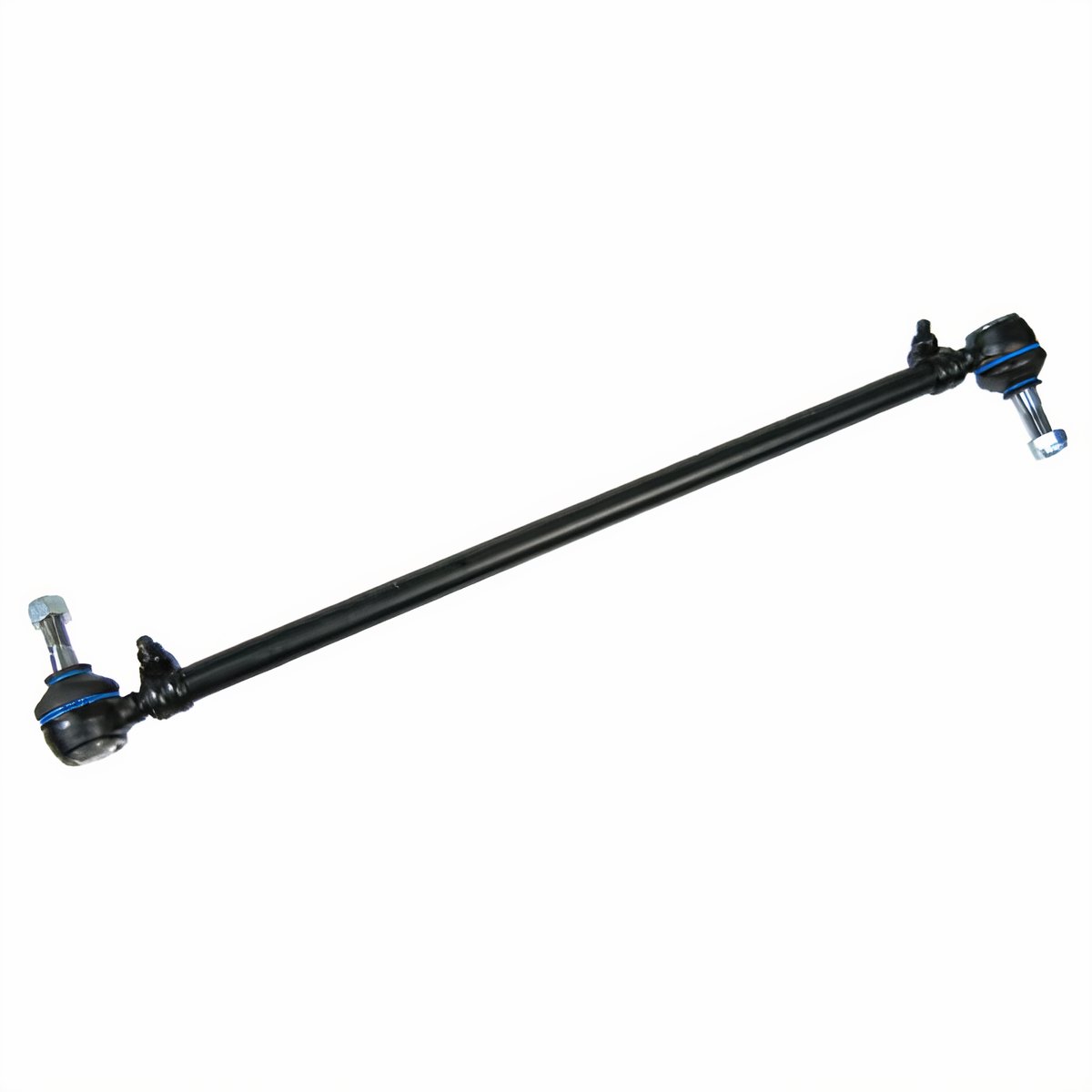
JBugs image of a tie rod
I ordered a pair of tie rods from Discount Import, and had T pick them up for me while he was there getting parts for Nemo (the A4). They charged me $35US each. The replacement was fairly easy. I started with getting the wheels as straight front-to-back as I could, centering the steering. Then, I replaced an entire arm, one at a time. The arm runs from the swing lever to the steering knuckle across the rear of the front beam. Each end of the tie rod has a 90* "end" on it that allows for controlled rotational movement. If the end can move at all any other way, it's bad. Since one of my rods was bent, I replaced the whole assembly, ends and all.

Rods Out
The ends are nutted down with castle nuts which are held in-place with cotter pins. The cotter pins may have rusted into place on yours, requiring more coaxing than mine did. Even as original parts, I was able to bend the pins back and push them out. Then the nut comes off. Last, the end needs to be separated from the knuckle or swing lever. This usually requires a pickle fork and a hammer, which will destroy the rubber boot on the tie rod end, so be sure to plan accordingly. I was able to free the tie rods by hammering away on the pickle fork. The passenger side released from the swing lever with just a couple whacks. In contrast, the driver-side steering knuckle took many many more. I have read of some needing to apply heat with a torch to get these to separate, so be prepared. Once removed, I cleaned up the holes with some WD-40 and a rag. Then, I scrubbed them with some sandpaper to make sure there weren't any sharp edges left around the holes from my removal efforts.

Rods In
Nicked from Interweb,
shows swing-lever end
and steering dampener
Oftentimes, the supplier will sell/send you two adjustable rods. This may be correct for some cars, but for the old bus, one of them is supposed to be fixed length. Discount Import only carries the adjustable rod, so the opportunity to do this wrong goes up. I followed this process for the not-bent side: measure the old rod from end to end on the top side (opposite where the threaded bolt comes out). I then adjusted the replacement arm to that same length, and then tweaked it until it dropped right into the holes. For the bent arm, this process wasn't effective. Measuring a bent arm wasn't going to get the exact length, so instead I matched it to the not-bent arm on the other side. Rather than touch the steering wheel or the tires, I adjusted the arm until it dropped into the holes. With the arms in-place, I could do a ShadeTree front alignment. Replacing the arms took less than an hour, so even at my "my free time is worth $50 an hour" rough math, I saved over $350 doing it myself versus having HM Motorsports do it.

Steering Dampener
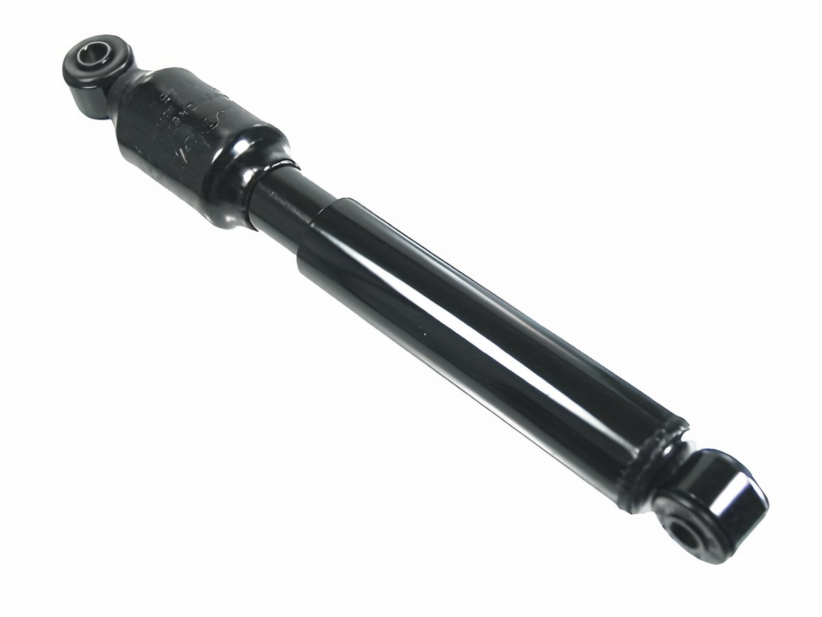
Jbugs again
Before I put in the new rods, I took the opportunity to replace the steering dampener. This is a small shock-absorber that helps cushion the driving experience at the wheel from sudden jarring affects of road hazards. Consider how much the steering wheel hops when you hit a pothole. For a car with a working front-end, it's not too bad. If your steering dampener is shot, the steering wheel gets a mind of it's own for a second. That's dangerous at any speed. In the bus, with the higher center of gravity, it's downright scary. I highly recommend replacing yours if you have no idea how old it is. I got mine when I got the tie rods for $30US. It's held on with 2 bolts (17mm, if I remember right), like a shock absorber, and it is actually pretty easy to get at when the tie rods are off.

ShadeTree Front Alignment
With the steering dampener and tie rods refreshed, I was ready to get the alignment roughed in for a test drive. All cars are a little different, so the measurement below may not work on yours, but it worked on the bus.  Measure the distance between the front-most part of your front tires (looking at the front left tire, at 9 o'clock). Now compare that to the distance between the rear-most part of your front tires. The measurement from the front should be between 0" and 1/4" smaller than the measurement from the rear. The varying length depends on your tire size; I'm running stock diameter, so this works. Ultimately, this effort should be sufficient to get you to the alignment shop. This is not an ideal permanent setting.
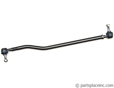
PartsPlace.com image
If you have just one adjustable tie-rod, the adjustment is more straightforward. Since I had two, I adjusted both sides one turn at a time until I hit the 1/4 inch number. Based on how the arms adjusted, I used to have no-toe or a slight toe-out. In my experience, the steering becomes less predictable with toe-out, so I'm good with a slight toe-in. I test drove the bus first slowly in the driveway, then into the dead-end street and finally around the block. The steering held much more firmly over bumps and when the street was level, and there were no bumps, it held a straight line with my hands off the wheel. There was still 3-4 inches of play at the wheel, though, when I did want to change direction.

Drag Linking
To resolve the remaining play at the wheel, I asked Boo to sit in the driver seat and turn the wheel left to right while I laid-hands on various parts of the steering system. I could see the steering coupler turn, and feel the arm move, but the drag link didn't move right away. It had a significant delay, and made a clunk noise when she changed direction from right to left (not left to right, which was weird). I rested my hands on the swing lever to see if it had any up/down movement. I couldn't feel any, so that lever and the pivot pin should be fine, unless my novice hands couldn't feel well. Other than the steering box, the swing lever was all that was left if replacing the drag link didn't fix the steering play. I resolved to replace the drag link, and bought one at Discount Import ($50US). If they had had a swing lever kit, I would have bought one since the 90 minute round trip can eat up a day if you need to do it more than once.

old drag link,
broken pickle fork
The drag link removes just like a tie-rod: pull the cotter pins, remove the castle nut, and apply force with a pickle fork to pop each end free. The drag link removes and installs from the front with the non-adjustable end pointing to the rear. I broke my pickle fork as you can see in the picture to the right. I guess the Harbor Freight fork isn't made very well.

Similar to the tie-rod, you want the replacement to be the exact same length as the old one. In the PartsPlace.com image above, you can see an adjustment lock-nut on the right end. I placed my old and new side by side to get the length correct. Take care as you pass that rear "end" through the hole in the support so you don't damage or tear the rubber boot. I left the plastic shipping cover (visible in the picture) on the end during pass-thru so it wouldn't get damaged. To get the end to fit into the swing lever, I put a socket extension onto the bolt and used that extra torque to position the bolt to easily fit onto the hole. The front end slid right in without any extra fiddling, so I knew I had the length right. If you aren't so fortunate, repeat the measure and fit steps otherwise your steering will not align properly. Last, I threaded and torqued on the nuts, inserted the cotter pins and closed up the belly pan.

Test Drive
This final test drive was quite different. The steering is genuinely responsive, with less than an inch of steering wheel movement before the bus starts changing direction. When combined with the steering dampener, it drives like a completely different vehicle. I know I should take it to have the alignment done, but honestly, I probably won't. It handles so well, holds center during acceleration and braking. Since the caster and camber were within spec before I started replacing parts, and the parts I replaced have no bearing on those settings, I may let it ride as it is.

So, Hapy is fully operational again... just in time for winter. I have plans to address rust this winter, after I complete the interior of the MGB. And, of course, there's the 280ZX that neither C nor I have given much attention to. Clearly, I have lots of content waiting to be generated.

That's it for today. Thanks, as always, for following along-

Tuesday, August 21, 2018

Ignition Re-Assembly

In my last post, I described the tear-down of the ignition assembly of the old 1972 VW microbus. Today's post covers the re-assembly.

Some Part Suppliers Are Better Than Others
I mentioned that I found a bus wrecker in Washington who sold me a lock housing for $75 plus shipping. What I learned when I opened the box was that the lock housing came with an original key cylinder and key. The seller had stored the housing, cylinder and key all oiled up and in a zip-lock baggy. The key works the mechanism flawlessly. They included the small set-screws which hold the housing into the black box. Avery's Air Cooled, you rock. I wish I'd found you years ago. You'll be my first call now.

Lock Cylinder, Housing and Sub-Harness
new plug has exposed
solder so I taped it off
The Bentley has re-assembly instructions. I tried them. They didn't work. The book says to install the housing, then put in the lock cylinder and then, once everything else is in place, install the electrical sub-harness. Yeah.. that last bit doesn't work. The harness is constructed so that the wire bundle comes out to the side, not straight out. In general, that's good, but once you orient the plug to the housing, you realize that the wire bundle comes out the completely wrong way, running almost rear-wards. Holding the housing up with the plug facing you, it comes out around 4:30. Ideally it comes out around 9:00. So, to plug it in, and have it click home, the wires needs to double-back on themselves in a very tight area while you are somehow applying leverage for it to snug in. Physics just won't comply.

So, we do it differently. Before I started, I removed the lock cylinder from the housing and test fit everything. First the harness, then trying the lock cylinder first to see if there were any serious issues with doing the lock cylinder last. Nope. Since the harness was already wired into the bus, all of this was done using the driver seat as a work bench. So glad it's Summer, by the way. I plugged the harness into the lock cylinder and made sure it clicked home. There is only one way to get this all the way seated, with a larger tab fitting into the larger slot and a smaller tab into the smaller. I even tested whether the key, housing and sub-harness would trigger power, so I hooked up the battery and turned the key to the run position. I could hear the click-click of things getting juice, so I considered the test a pass.

Into Darkness
turn signal wire bundle
With the harness in the housing, we now twist into a pretzel to fit the housing into the black box. For reference, consider that the entire steering post, etc had been back together only to discover that the old housing wouldn't work. Recognizing how difficult the tear down was before (3 full days), I wasn't going to do that again. So, the black box is on the steering column with the rubber bushing, and such in place. The housing takes some fiddling to get into the right orientation, in part because the harness is plugged in, but mostly because it is not exactly parallel to the bottom of the black box. It tilts up to the right (towards the key opening). Once the tabs find the slots, you need to press the housing firmly as deep as it can go into the slots while tightening the set screws. This took a few tries, but once it was in the right place and the set-screws cinched down, I could start to see the light out of the dark

Key Lock
With the housing in-place, the lock cylinder can slide home. This is a do-it-once kind of thing. If everything isn't lined up right, and you need to pull the lock cylinder again, its a multi-day job. Things looked good, so I slid it home. It fortunately had no issues.

Other Discoveries
In my case, we believed the ignition fry was caused by either the heat/defrost fan or by the headlight switch. So, I removed the wiring for the heat/defrost fan and replaced the headlight switch. As happens these days, the headlight switch was faulty out of the box. I had to wire both the running lights and the headlights out of the same pin because the pin for the headlights simply didn't work. Also, the new switches don't come with a pin for the idiot-light on the dash, so I wired that into that same pin. Now, when I pull the stalk out one spot, the running lights, headlights and idiot light all illuminate. Nice.

While I was removing wires for the heat/defrost fan, I installed a new switched 12V wire along the same route. Following older VW coloring, I used black, and tied it into the furthest right fuse, the switched 12V for the coil used to come from. Now, when I turned the key to run, I have a nice strong signal for the new-engine electronics. But there was more darkness ahead. I'll get into that next time.

Thanks for following along. I'll wrap this up next time

Tuesday, August 14, 2018

Ignition Switch Teardown

This will be the first of 2 posts covering the efforts to resolve the damage caused during the electrical fire we had while driving home from 4Peaks (See 4Peaks 2018 - Road Report).

Recall... I looked down and smoke started first as a wisp and then as a billow from between my knees. We were fortunate to have a small road intersecting with the highway, so we dodged onto the shoulder at the corner, turned off the ignition and flipped on the hazard lights. I jumped out to make sure the hazards were on and saw the headlights were lit even though that switch was off. I went around back and removed the positive battery cable, thinking that the electrical was completely borked....

Roadside Findings
As I mentioned in the road report, we pushed Hapy under a tree. While Boo made peanut butter and jelly sandwiches, I twisted into a pretzel between the front seat and the steering column to see what was going on. The wires leading into the steering column were still hot. One of them was down to bare copper wire from just past the fuse box all the way past where my fingers could reach: a goot foot of plastic insulation had vaporized into smoke. I think if we'd gone much further without killing the electric, we would have either fried the battery or had the fire spread into the fuse box. Either could have spelled ruin for Hapy. As I said in that prior post, getting into the electrical solve required a 27mm socket to remove the steering wheel, so we got a tow.

Home-Drive Findings
160 miles (and $300US) later, Hapy was back in his usual tarmac-paved spot in front of the house. With the camping gear removed, and a good night's sleep, I was able to look at what was going on. My initial fears that my entire wiring harness had failed were not realized. I don't think. The sub-harness that runs from the fuse box to the ignition switch, however, was completely toasted. I concluded that the headlight switch was in need of replacing too, since the headlights flickered on the way to 4Peaks and were on without explanation when we broke down.

Extractions
I started following the Bentley to get access to the badness. Bentley documents this fairly well: remove the horn button and cancel ring, remove the steering wheel nut (27mm socket). Using a gear puller, remove the steering wheel, but they don't say anything about pushing the wire for the horn into the steering column. If you don't, the gear puller will probably cut it off for you nice and cleanly right where it comes out the steering column. Ask me how I know.

With the steering wheel off, you can remove the turn signal housing, leaving the turn signal hanging by it's bundle of wires from the black box. The black box is held to a silver support with 4 Phillips bolts. When these are removed, the steering column can pivot at the bottom. So, it is wise to remove the clip-ring, washer and rubber bushing. At least that's what Bentley says. The top of my clip-ring was so full of crap, I couldn't get to it. Also, that rubber bushing had never been off, so it wasn't inclined to move. Fortunately, the ignition sub-harness had burned so badly that it just fell out of the black box. So, the only things holding the steering column and wires was the column base and the wire bundle for the turn signal. The turn signal wires unplugged and the whole steering column came out as an assembly.

I had to loosen the black box from the column thru judicious use of a rubber mallet. First, I cleaned the top, removed the clip-ring and washer and shot lubricant around the rubber. It wouldn't give without a fight. Once apart, I could focus on getting the ignition cylinder separated from the housing. Now, the housing and lock cylinder were also original, so they had become very friendly. The housing removes (with the lock cylinder still attached) by removing these 2 little hidden bolts from within the rear-most bolt holes that held the black box to the silver support. With a little coaxing, the housing will come out with the lock cylinder still attached. The 72 and later (not sure about how much earlier) lock cylinders are held in with a small spring. This spring can only be compressed through a hole through the housing near the end where the cylinder goes in. This spring can also only be compressed if it hasn't been compromised. Mine was. Badly.

Pieces
I tried compressing the spring in the hole with various pokey tools. None would budge it. Lubricants couldn't do it. I finally resorted to drilling the lock cylinder like a safe cracker. It didn't matter. When I finally got the cylinder pieces out of the housing, the housing was unusable. The fire had melted some of the plastic inside and my man-handling of the housing and cylinder had made it's use uncertain. I figured I'd just order another one and be on my merry way. Uh... no. This housing isn't manufactured anymore. It's not on the internet enthusiast site classifieds. I found one on eBarf for almost $180 (shipped), but the seller wouldn't guarantee that it either worked nor that it would arrive within a month. So, I spent several hours hunting down small VW crackers, and found one in Washington who had one and sold it to me. $85US shipped.

Costly costly
So, the running tally for this mishap.... $300 for the tow home. $20 for that old switch I had lying around. $85 for a new housing. $25 for a new ignition sub-harness. I decided to replace the headlight switch, in case that was part of the problem, so add another $25. Add in the $180 for the complete wiring harness I bought but BusDepot won't accept as a return. Add in the $200 spent on a hotel for the shows in Eugene where we intended to camp but couldn't because Hapy was stuck in the driveway. Add $150 for a replacement steering wheel after I chipped my original during the extraction. AND, I haven't even done the assembly yet, so there may be more costs yet to come. Running tally: $785.

I'm ending this post genuinely more optimistic than I sound. This is an opportunity to improve lots of things as I go. The black box and the turn signal housing can get cleaned up so they look nicer. I can upgrade the steering wheel to one of those fancy wood ones for another $100. The key cylinder will be new so turning the key will no longer be a frustrating experience. All told, the ignition control and the area where I spend the most time will be much improved once this is done. Oh, and the engine will start and run again. So that's nice.

Thanks, as always, for following along.

Tuesday, November 14, 2017

MGB - Test Start, Test Drive

Today's post covers the initial tests of all the changes that I did this past year on the little MGB. It's been quite a year. In August of 2016, I picked up a little British car to bust my knuckles on over the winter. I needed a break from the bus, and it looked like it was going to be a cosmetic fixer. As you've read along this past year, you learned as I did that there was much more to it than that. The brakes were squishy on the drive home, so I went to redo them only to lose the master cylinder in the process. I went to replace the brake master cylinder and had that scope explode into redoing the clutch master cylinder as well. We found rust-through in the floor under the nasty carpet. We found the front suspension bushings has been replaced with window insulation... or at least it looked like it. The coolant pump was failing. The fuel tank was leaking. So much to do and fix. Before I turned the key, though, I changed the oil and oil filter.

Hydraulics
We replaced both front disks, pads and hoses. In the rear, we replaced all of the brake parts: shoes, hardware, drums, wheel cylinders and the one hose. We replaced the brake master cylinder and polished the vacuum assist. Last, we replaced the fluid from end-to-end (kinda obvious with everything else getting redone). On the clutch, we replaced the master cylinder. Between the two master cylinders, we tore down, cleaned and painted the pedal box and pedals. The pedals got new rubber pads as well. Detailed postings 1, 2 and 3.

Body
We ripped out the passenger and driver floors. The rails were repaired, flattened and ground to bare metal. We measured, drilled and ground-to-metal for plug and seam welding the new floors and then had a party to weld them in. The seams were sealed with black seam-sealer and then we experimented with flex-seal to 100% fill the little gaps. Undercoating was applied. I didn't post on it, but in the rear of the little cabin, a prior owner (PO) had cut a big section out of the wall between the cabin and trunk. I repaired that big hole while leveraging the opening to install 2 6x9" Polk Audio speakers. The trunk lid was removed, cleaned, splits were welded and the underside painted. The trunk floor was cleaned, painted and sound deadener was added. The lid had new hinges installed, and the gap on the driver-side accounted for with washers so the trunk now seals all the way around. Detailed postings 12 and 3.

Fuel
The tank was removed and sent to a radiator shop for cleaning and lining. All new fasteners were used during install, and we replaced the hoses, hose clamps, and float / level-sender. Up front, new hoses were installed and a discovered-to-be-faulty upside-down safety switch was replaced with another filter. I will be restoring a safety switch later. We discovered this system leak during final system testing. Detailed posting here.

Cooling
One of the first things we learned about from British Auto Works was the failing coolant pump. This system was the last to get our attention, though. We pulled the pump and the radiator. The radiator was treated with a vinegar and distilled water solution to de-rust / de-scale as was the heater (though it was done in-place). The coolant overflow bottle was paint-stripped and polished and a new pump installed. All new hoses and mostly-new hose clamps were installed as was the thermostat and thermostat housing. Detailed postings 1 and 2.

Front Beam
Second in scope only to the floor replacement, I spent last winter rebuilding the front suspension and steering. The steering mechanism got a clean-up, new gaiters, oil and new tie-rod ends. The suspension was completely refreshed, including new poly-impregnated rubber bushings all around, lots of paint prep and painting, new lower control arms, new front shocks, new front wheel bearings and upgraded sway-bar bushings. It's practically an entirely new front end. Detailed postings about the steering here and here, the front beam 1, 2, 3 and 4. Let's not forget replacing the engine mounts. That was fun.

Testing
Along the way, everything was tested to some degree. The cooling system doesn't leak at rest. The suspension doesn't make noise no matter who is jumping up and down on the bumpers. We stomped on the floors from above and beneath. The clutch engages when the pedal is depressed... and the engine isn't running. The brakes stop the car from rolling when nudged in the garage. These little tests gave us confidence to keep going, and believe that the system was ready. Eventually, you have to put gas in the tank and turn the key.

The last thing you do before you test is hookup the battery. I verified that the battery still had 12V (I was shocked it didn't need a charge), and then connected the leads. The key had been turned to RUN to unlock the steering, so the fuel pump started up. Fuel fountained under the hood, so we tightened a few things, and ultimately removed a broken flip-over safety switch. Once solved, I hopped into the driver seat, put the car in neutral, pulled the hand brake and turned the key again. Fuel pump started up, so I waited a second. After confirming that the gas-fountain wasn't happening I turned the key to start. The engine fired up almost instantly. I revved the engine a few times, and looked for exhaust color. There really wasn't any exhaust, so early concerns about running rich may not have merit. No black smoke to indicate oil nor sweet white smoke to indicate coolant either.
Test Successful.

A Drive
Running the engine in my garage felt awesome, but to really test many of the systems, we need some straight road, and more gas.. and a seat for a passenger and some seat belts. With the new floor came new embedded nuts for the bolts for the seat. this made the seat install a 10 minute effort even as I helped C on his new ride. Add in the retractable seat belts I bought last fall and I'm ready for a street test. Once the rain stops. Oddly enough, during the overnight after the test start, the battery ran down to nearly 0. I must have left the key in the ACC or RUN position, causing systems to stay active all night. Jeez. Road test has to wait while I charge the battery. While waiting, I noticed the front driver running light wasn't working and fixed it with some DeOxit and some patience. I rooted around and found a couple of bolts which could hold the steering column plastic covers on and put that together. I found myself wiping down seats and fiddling with things waiting for the nice weather to arrive.

Finally, I had an opportunity. We had an unseasonably nice stretch during the week and the weekend following was absolutely stunning: upper 60's and clear skies. So, I moved the herd of cars around the driveway, and pushed the MG out of the garage. With a clear rear-view to match the clear sky, I jumped in, fired it up and backed down the driveway. It's loud, and after a little it's-cold sputtering, it settled down. I was able to move through the gears easily; the clutch responded very well. The brakes still had some spongy in them, but I sped off down the street anyway. I drove maybe a mile around the neighborhood, and then started noticing all of the systems that were not working: everything on the green circuit. I chose not to drive to the gas station and instead drove home.

Upon arrival, I discovered that the thermostat housing was leaking. I torqued it down with a plan to look for a leak there on my next test flight. No gas leaked from any fuel line, the brakes remained consistently spongy so I'll need to do another round of bleeding there. The exhaust is loud everywhere with pop-pop-pop noises on deceleration, telling me there's an exhaust leak. Maybe multiple. Let's not forget the green circuit isn't working. Ultimately, though I declare Test Successful.

It was awesome to get that little car going. The throttle response is great, the steering is tight, the suspension over bumps is mellow. I have a few things still to do before it's really road-ready, but none of it is scary. Except maybe getting a top. That may have to wait until I can pay someone else to do it.

Thanks, as always, for following along.

Tuesday, July 11, 2017

MGB - Steering Rack Install

I realized that I didn't post about the install of the steering rack, so today I'm going to have a quick post about that. For reference, I removed, cleaned and re-assembled the rack in this post.

Pre-Alignment
steering arm seated in clamp
Before you start putting the three-armed monster in (what's that? See MGB - Steering Rack), check that it's centered left-to-right by turning the steering arm. Next, check that the steering wheel is straight, the center spokes level with the bottom of the car. On the other side of the firewall, you should be able to spot the steering column butting out. There is a clamp on the end for the three-armed monster to fit in. The clamp has a bolt/nut combination which needs to be removed from the clamp before assembling the three-armed monster. That bolt needs to align with a cut-away on the three-armed monster steering arm. So, look at the two ends, and recognize that if the steering rack is centered within itself, but not centered once the cutout aligns, your steering wheel won't sit nicely level. Fixing this could be as easy as a minor adjustment during alignment, or more complex like removing and re-installing that clamp or doing something to the steering rack. In my case, I was putting the old rack back in, and the wheel was close to level before.

In She Goes
If you're doing this alone, like I was, getting the monster in can be a juggling act. The column arm fits around the right engine mount bracket. Get the unit in the right general location, and use a rubber tarp strap to hold it there. Believe me, holding the monster in the right general location while also trying to do the fine motor work of getting the arm into the clamp is simply impossible by yourself. Once successfully suspended, set the steering arm into the clamp. If the clamp is not amenable, it has a split down one side where you can coax it open with a wedge. Once you have it in the right alignment, slide under the front of the car and drive it into the clamp with a rubber mallet driving against the housing. It should slide in with only a few light strikes. Remember, that's a $250 part, so rap on it gingerly.

The rack is held to the frame with 4 bolts and 4 nuts with some washers. Get replacements. The bolts closest to the firewall drive into nuts which are part of the mount. They thread in pretty easily. Just do enough to get the threading started. The bolts closest to the front use a pair of nuts each. Yes, I said that right. The order of the fasteners from the top: bolt head - washer - steering rack - nut - frame bracket - washer - nut. The nut between the frame bracket and the steering rack is absolutely necessary to not bind the steering action. Yes, I tried it without the nut to see what would happen.

Tie-Rod Ends
I blasted The Roadster Factory for their return policy and continued sale of junk tie rod ends. Get the sealed OEM ones, and use a different vendor if you can. There are a few out there. Assuming your new ends are the same size as the ones you removed, you should be able to thread the new ends to the marks you made earlier. I determined during my "Rough Alignment" that my new ends had more housing to them, knocking my measurements off. Had I to do it again, I would measure from the edge of the steering rack housing to the outer edge of the tie rod end instead. Regardless, thread on the tie-rod ends and set the wheel-end into the arm on the swivel, and finger the washer and nut on. Don't tighten yet. There's rough alignment to do first.

Rough Alignment
There are a few ways to get the alignment roughed-in. By roughed-in I mean close enough to drive it to a shop to have someone with a machine do it. It's possible that you could do it as well with one of the methods, but I encourage having it verified. The easiest method is simply looking down the line of your car and matching the front wheels front/back along the body line. I did this first, once I discovered how toed-out my front wheels were.

Changing your alignment is pretty easy: pull the tie-rod end out of the steering knuckle and rotate it on the tie-rod clock- or counter-clock-wise to move the end in or out relative to it's prior position. There is an alignment lock-nut just to the inside of the tie-rod end that will need to be loosened before you play with the adjustment.

After the body-line rough-in, I would encourage the measuring tape method to rough-in your alignment. Measure the distance between the inner edges of your tires both behind and in front of the swivels. If they aren't the same, you may have adjusting to do. Ideally, the front is slightly narrower than the rear for better handling and stability. This measurement should happen with the wheels on the ground after wiggling the steering a little bit and then centering as best as you can. It will take a few tries to get it right. Once you think you have it, tighten the lock-nut and test it in your driveway. I still need to complete this on my MG, but the steering is close enough now for me to move the car around my driveway / garage.

Regardless of which rough-in you try (and there are probably others), don't assume it's right. The idea is simply getting it close enough to take to a shop. If you aren't confident with your rough-in, have it towed. If your car is anything like my bus, it's getting used to riding on a flatbed.

That's it for today's brief posting on getting the steering rack back in. More to come soon, and, as always, thanks for following along,

Friday, May 26, 2017

MGB - engine mounts

One of the first things I noticed that needed to be addressed when I bought the little British car was the condition of the engine mounts. "How?" you may ask. I intended to replace the alternator belt and couldn't because the engine was sitting so low in the engine compartment there wasn't enough room between the bottom pulley and the front beam to fit a belt. Today's post covers the fun of replacing the engine mounts without removing the engine from the engine compartment.

virtually 0 clearance
Parts
This seems obvious, but there's more to the story than just the rubber mounts. They are sold individually, but they're not expensive. The originals are around 10$US, but there are upgraded versions for 13$US. If you're going through the trouble, it's worth the $6.

The mounts attach to the frame of the MBG onto mount points which are welded on, one per side. These have a vertical slot in the center for the body-side bolt on the rubber mount. The other side of the rubber mount attaches to an engine mount bracket. With the age of these cars, the bracket often has issues hidden behind the rubber mount. My passenger-side bracket was both bent and cracked. Neat. These were $6 a piece. So cheap. Crazy cheap compared to modern cars or even the old bus.

Last, you'll need fasteners. Those old nuts, bolts and washers are as old as the car, and probably more rusty. These old British cars have lots of different metals in them, increasing their tendency to rust. So, get stainless if you can or zinc-coated if you can't. Plain steel will rust again. All of the nuts and bolts fit a 1/2" spanner except the nuts which fit inside those welded-on mount points on the frame and the lower bolt on the bracket. Those are 9/16". To replace the mounts and the brackets, I got 8 1/2" nuts with matching lock washers and 4 bolts, each just 3/4" long. These are all fine thread. I also replaced the bolts on the bottom of the mounting brackets. They need to be 3/4" long. I tried longer bolts but they bottomed out.

Tools
bent bracket on right
Similar to most of the other projects I've done on this car, the tool list grows as fasteners get harder to reach or harder to remove. PB Blaster (or a like product from the WD40 folks) is critical. 1/2", 9/16" sockets and wrench. Spanners in the same size plus a breaker bar. Floor jack and a small piece of wood 2x4. With all that hardware, the single most important tool is your patience. I kept running out and having to go looking for more.

Process Out Prep
I read a bunch of different opinions before I started. While the mounts are usually replaced when the engine comes out, it isn't required. Some have found that removing the steering isn't necessary. Not me. I couldn't have imagined this with the steering still in place. See, the steering column runs straight through the welded on frame mount on the driver side, making it all the more difficult to address the nut contained within. Some folks have taken a cheap spanner and ground it down thinner to fit between the column and the mount. Fortunately, I still had my steering unit out, so this was academic for me. My advice: remove the steering rack. See how in (MGB-steering rack).

On the passenger side, the alternator blocks easy access to the mount. This is very easy to remove, and you already have the right tools: 1/2" socket to loosen the belt and then a couple 1/2" spanners to remove the mounts on the top. Don't forget to unplug the 2 wires on the back. And, just like that the alternator is out and you can easily see the mounts.

Once you have clearance to get at the mounts by removing the steering rack and alternator, you're pretty much ready to go. Jack up the front end and put it on stands so you can easily get after it from above and below. Then, put that block of wood on top of your floor jack and set the jack under the rear edge of your oil pan, where it meets the transmission. This is it's strongest point. Raise the jack until the weight of the engine is mostly removed from the mounts, and is instead on the jack/wood combo.

Process Out
Pick a side. To stretch my patience, I would do a little on one side until I grew frustrated and then moved to the other side. Start with the nuts which hold the rubber mount to the bracket. These are the easiest to get to. The bolt closest to the driver doesn't have a bolt head on it so it could free-spin on you. Yes, that's frustrating, but with some pressure applied with a screwdriver between the free-spinner and the engine block, I was able to get the nut off. Next, get after the nut that is semi-captured within the frame-side mount. A spanner can only move about 1" up/down at a time, and then you need to flip it over or use the box-end to move it another inch. This tests patience. Once the nuts are removed, raise the engine until you are able to free the mount from the bracket and frame mount. I also leveraged my breaker bar as a lever to tilt the engine a little bit so I didn't have to raise it as much.
right (p-side) replaced

With the rubber mounts off, remove the bolts holding the brackets to the front of the engine. Last, remove the bolts on the bottom of the brackets. This last bolt is very hard to get to until after the rubber mounts are gone, and even then it is partially obstructed by the sides of the bracket. Patience. Once the bolt is loose, I was able to spin the bracket off by hand, not bothering with anything other than a socket on the bolthead to keep it moving with the bracket.

Process In
The install is the reverse, but it was advice like that which inspired this blog all those eyars years ago, so I'm going to run through it. Start with the bolts for the bracket. Don't torque it down, just get it threaded on and then shift to the smaller bolts which attach the bracket to the front of the engine. The bolts go in from rear to front. While this may not look as clean, the rubber mount will dig into the end of the bolt sticking rearward if you don't do it that way. Yes, I did this first. Once the bracket is loosely attached, torque down the smaller bolts and then the large one. If you do it in the other order, the bolts in the front part of the bracket can get hung up on a slight misalignment and you'll have to do it over. Yes, I did this too. :)

With the brackets in, re-raise the engine so you can fit a rubber mount in. I did the driver side first, but I don't think it matters. The driver-side bracket has that one weird bolt that doesn't have a head. I found something that would work at the hardware store, but needed to bore out the hole in the bracket to get it to sit deep enough so the bracket would align properly on install. Crazy. Once that is solved, plop the driver-side mount onto that bolt and shift it into position such that the frame-side bolt is in the vertical slot. Short sentence; could be a long effort. I used the breaker bar as a lever to help that last little bit of space to slip the frame-side bolt into the slot. Get the lock washers and nuts onto the bolts. I found gravity to be a terrible partner in this, causing the frame-side nut to fall off the bolt and down into the nowhereland of garage floor multiple times. Patience. Once the nuts are threaded on, tighten as far as you can without tools. Remember how hard it was to get the spanner in that frame mount during removal? Yeah, just as hard on install.

left (d-side) replaced
Once you have the nuts threaded on as far as you can by hand, give them a couple of runs with a spanner and then lower the engine so the jack is no longer holding any weight. I tried to shake the engine a little bit on its way down to make sure it settled, but it didn't seem like the engine moved at all. Just the same, its a good idea. Once all the weight is on the mounts, finish the tightening with a spanner.

Finish up by re-installing the alternator, and the steering rack. Lower the car off the stands, clean your hands and your tools.

This job was a bear, but the engine sits at least an inch higher than it was. Between the bent and cracked bracket and the twisted / flattened mounts, this job was long overdue. While the engine won't run any better, I'd like to believe that any vibrations will be greatly reduced and the drive train is now aligned like it should have been coming out of the factory.

As always, thanks for following along. For my American friends, have a pleasant Memorial Day weekend. I greatly miss the old Hornings Hootenanny which used to fill my Memorial Day and am left unsure what to do with my 3 days this year. Maybe I'll pull out the welder...

Tuesday, May 16, 2017

MGB - steering rack

The last collection of posts have been about this project MGB I picked up last Summer/Fall. Today's post covers the efforts of removing, cleaning, and repairing the steering.

Context
The steering on these little British cars is only a hair more complicated than the old VW bus. The bus uses a system called "worm and peg", which is definitely not used in modern cars. Without opening up the steering box, consider that there is magic inside this box with two arms coming out it. The arm coming out the top connects to your steering wheel and the arm coming out the back connects to control arms that terminate at each of the front wheels. Within the magic box live the worm and peg. The "peg"  rides on the "worm" that is a threaded bar that looks like an auger. As the steering moves from lock to lock, the worm moves the peg from side to side, causing the front wheels to turn. Simple design.

3-armed monster
The MGB has a rack and pinion style. Rack and pinion has a gear (pinion) at the end of the steering column that rides on a "rack". The rack is simply a toothed bar to which the control arms are attached. In the case of the MG, the control arms and the rack are all one piece. Power steering includes more bits to boost the power of the pinion to move the rack. The MGB doesn't have the power assist, but its a tiny car with little weight, so there isn't much need. One other interesting bit about the MGB steering is that over half of the steering column is part of the steering rack so it has 3 long legs/arms to manage on extract and install.

Getting It Out
just removed. note torn d-side boot
Removing the steering rack from the MGB is actually pretty easy. For me, someone who takes forever to do even the most simple of jobs, that's a big statement. At the ends of the control arms are tapered "ends" that fit into the steering knuckles (sometimes called "swivels"). Since I had already decided to replace the rod ends, I separated the ends from the knuckles with a couple of smacks with a hammer. There are gear remover tools that are more graceful, but if you're replacing the ends and the nuts (always replace the nuts) anyway, a hammer works great.

p-side arm measured
With the ends separated from the knuckles, move up to the steering column part up near the firewall. Mark the way the two ends come together so your steering wheel will align properly on your first re-install effort. I shot the joint with a pop of spraypaint, but that was only because I couldn't find something like a paint pen. You can just see the marks in the picture on the right, here. Once marked, loosen the connection so it doesn't hang up on you later.

In order to easily get to the rack bolts, you may need to remove the little section of cowling between the radiator and the front beam. It is made of glueboard and held on with a couple of nuts. There are metal replacements for the cowling available, if your original is trashed. Once you have access to the rack, it is held on with 4 long-ish bolts. With those bolts removed, the rack can be removed by pulling it forward and down. If it isn't budging, check that the steering column is loosened enough.

Cleaning
p-side arm measurement
My rack was leaking, and was identified as a possible replace item by the shop. K2 and I saw that the bellows on one side were definitely torn, so I ordered a replacement set as well as replacement arm ends. We (step-son K2 helped a bunch here) started with simply cleaning everything up first. K2 used "Simple Green" and a lot of elbow grease to get the arms and main cylinder clean.  You can't put new bellows on while the arm ends are still attached, so when it was clean, I marked the control arm end positions with a shot of spraypaint (use a paint pen if you have one). Once marked, I removed the arm ends, and then the bellows. At this point, K2 doubled down on cleaning. He turned the steering from post to post, cleaning up any gunk that he found in the teeth. We removed the cover plate and looked for broken teeth on the pinion as well.

Repairing
Junk. Don't Buy These
The pinion had no broken teeth and the arms were in great shape. We decided not to replace the steering rack, and just re-seal the cover, refill with oil and replace the bellows. I used a very light application of form-a-gasket to help seal the cover. If you use too much, it gets into the gears, and that detail cleaning needs to be redone (guess how I know that). Before the cover plate is sealed on, the bellows need to be put on. Put a little bit of gear oil on the inside edge of the small end before you start. This allows the small end to slide over the end of the arm without tearing. Attach the wide end to the main cylinder and a-fix with the metal band. Before attaching the small ends, check where they should go so that they don't stretch nor bind when the rack is turned lock to lock. If you have marked the old location, its easy. I didn't but I found that once I started zeroing in on a spot, it actually was the same original position (there were tiny scratches on the arms). Tighten the small ends down with the smaller metal bands. Now, fill the system with gear oil: 90 weight (like the VW bus transaxle). "Fill" is about 8oz.

Ends
OEM. Buy These
Once everything above is done, all that's left are the ends. There are two kinds available out there, and I bought both to see the difference. These cars came with sealed ends that allowed no maintenance. So, if you thought your end needed grease, you can't grease it; you need to buy replacements. These replacements are made in England, though, so you're getting a good OEM part when you go this route. There are also replacements available which have a grease fitting. These are Chinese junk. The concept is great, the execution is appalling. The pair that arrived were rusty and the main rubber seal was falling off. Not only would it not hold grease, the rubber "seal" wouldn't stay on at all. I was only able to find them at the Roadster Factory, but don't shop there. When I alerted them to this poorly built part, and returned it according to their rules, I received no communication nor any money back. Vendor: if you sell garbage and then don't honor your own policy, you're a sham to me and will be called out accordingly: do not shop from The Roadster Factory unless you're willing to accept crap parts with no means of return.

Ends On
The OEM part, as expected, looked perfect and fit as you would expect. I threaded it on to the marks and tightened it down.

I am finishing up some other tasks before re-installing the rack, so I will post again when I have that completed. Thanks, as always, for following along.

Tuesday, July 8, 2014

Nye Beach Road Report

We took a road trip to the Nye Beach district in Newport Oregon over the July4 holiday.  This and the next post are dedicated to that trip. This one is just the travel report.

just North of Newport on US101
Getting Out of Dodge
Boo has a saying that goes something like "people will do what they want to do".  If you have a house of 6 people, all 6 need to want to get their collective stuff together and out of the house relatively early in order for you to get out early.  I had high hopes for being on the road by 11, but it was closer to 2 before we shoved off.  Ultimately, this worked out for the better, since that meant we could carabus with K driving his new-to-him Subaru named Kirby.  This split up the passengers and the payload too.  Still, Hapy was loaded down with 2 coolers full of food, all of the clothes, pillows, blankets, and most of the dry food... and 4 of the 6 travelers.

Wind-Blown Journey is the Destination
Since we were leaving town before rush hour, and it was mid-week (Wednesday), the traffic was trivial.  The drive out of town was trouble- and worry-free.  We followed the same route I took with T and C on our first camping trip with the new engine (see: One Small Step for Van...) down Roy Rogers and again as we entered the farmland of outer Beaverton, we expressed thanks to all of those who helped us along the way.  It's a tradition now.  We waved at the NAPA in Sherwood who helped us on that trip and again told the tale of how they helped us solve a hose-coupling design flaw.

Yamhill county grape region
Once we were outside of Sherwood, the towns are spread further apart.  First Newburg and Dundee, then Dayton, McMinnville.  By McMinnville, the increasing cross/headwind started to make steering an adventure.  If you haven't driven a bus or other tall flat-sided vehicle, you don't know the true terror of having the wind suddenly shift you 8 or 10 feet to the side.  It wasn't that bad, but with those kinds of memories in mind, I could feel the stress creeping in.  So, we stopped at the Dairy Queen near Sheridan for cheap eats and a couple Blizzards.  Shortly after leaving Sheridan, the flat farmlands give way to the Coast Range foothills, and corresponding forests.  The winds slowed as we passed the Spirit Mountain Casino and our adventure shifted from holding the wheel against the winds to climbing steep inclines.

For the most part, we were able to maintain the speed of traffic (55 MPH) through the foothills, the Coast Mountains and even along the 101 to Newport.  Of course, there are always those who want to go faster and will express themselves as they pass.  How sad for them that they are unable to enjoy the beauty around them and can only focus on the endpoint of their drive, spreading negative energy as they go.  There were a few longer inclines which were especially challenging.  There is one run south of Lincoln City that I had to run up at 35 MPH in third gear.  Even with the new engine, pushing over 4500 pounds is hard.  At no point along the entire run did Hapy's engine temperature go above 194*F, and every time it rose above 185*F it was during a long hill climb after which it immediately dropped back to 185*F again.  All told, he ran extremely well, pulling us into our destination around 6.
Devil's Lake

At Nye Beach
Hapy was warmly welcomed by the family when we arrived.  Little cousins who hadn't met him before climbed around inside, clearly amazed at seeing something so old.  We realized that Hapy is one month older than my younger brother and brother-in-law.  Funny stuff.  While at Nye Beach, we didn't drive almost at all.  We carabus'd with K, and sent him and brother T to the store for forgotten foodstuffs in Kirby.  We took one drive up to Lincoln City on Saturday to visit Devil's Lake.  The drive into Lincoln City from the south was a slow plod because of some road construction, but otherwise, it was just another mellow smiley drive in a 40+ year old microbus.  We put his pop-top up at the lake, creating a private changing area for us.  The nieces especially liked that.

I have discovered that Hapy is leaking some form of oil, but I can't determine the source.  When I check his engine oil level, it checks out virtually unchanged, but he continues to leave little puddles.  The drip also gets caught in the passing air and is creating a spotty film on the rear of the bus.  Me no likey.  I intend to dig deeper into this leak this weekend.  I think it's transaxle gear oil.  We'll see...

Home-bound
Happy in Hapy along hwy101
We had "check-out" at 11 on Sunday morning.  I quote check-out because there wasn't anyone to hand a key to, and no one was waiting for us to get out so they could get in.  Honor system, though, had us out of the condo by 11:30.  We didn't really have an agenda, so we pointed ourselves north on the 101 seeking coffee.  We couldn't find an easy-to-get-to coffee shop anywhere on the 101 through Newport, Depot Bay and most of Lincoln City until almost the end of town, there's a Starbux on the north-bound side.  To be fair, we could have tried to turn left across 2 lanes of southbound traffic and then try to turn left back afterwards, but this was end-of-holiday weekend traffic.  No chance.  With coffee's in-hand, we set off into the bumper-to-bumper traffic.  I could create an entire post about the ridiculous driver behavior we saw.  Maybe I will, so I'll leave it out of this report.  Needless to say, there were unexplainable traffic slowdowns and delays.  We stopped at the Dairy Queen in Sheridan again for a late lunch, and tried the trucker scales on OR18.  We scaled out at 4550 pounds.  While the outside temperature rose up into the mid 90's, inside the bus wasn't uncomfortable.  In fact, we didn't really notice the heat until it was time to unpack the bus.  After 2 prior attempts to have a coast trip without an issue, this, our 3rd try, was successful and issue-free.

Statistics
270 - total miles traveled
26.2 - miles per gallon

That's it for today.  More next time on Nye Beach, the family visit, the condo's, the Hatfield Marine Science Center, fireworks, Devil's Lake, etc.

Sunset at Nye Beach