Showing posts with label oil. Show all posts

Tuesday, March 10, 2026

Hapy Drives Again

It has been a long 18+ months without having a member of our family kicking around with us. But, Hapy is one injection-pump re-seal away from daily-driver status. Today, I'll go through the last little things. Again, my regrets for not taking many pictures. I have been away from fixing and blogging so I have fallen out of the habit of snapping a picture while I'm doing the doing. Also, I got hit by whatever flu thing that's been going around and was flat-backin bed-ridden for the last 3 weeks.

Clutch Adjustment
post-test drive
I touched on this at the end of my last post. I had to add an extra small spacer at the end of the Bowden tube as well as on the very end adjuster. To be fair, I really didn't need the one on the adjuster, but I would would not have much adjustment thread left if I hadn't. I ordered a replacement clutch cable and when it arrives, I will keep it under the rock-n-roll bed until I get to replacing it. I expect I will replace that cable relatively soon, but I want some fun drives before I take him off the road again, even to do something that I could do (and have done) on the roadside.
 
The standard adjustment advice is to shift the tension on the cable as felt by your foot on the pedal such that there is no engagement until the pedal has moved a good inch down towards the floor. This prevents premature wear on the clutch and/or throwout bearing. You don't want the throwout bearing riding on the clutch spindles all the time. That's noisy and introduces premature wear. What I did not recall from prior clownings on the cable was that the arm protruding from the transaxle would have so much play in it before the throw-out bearing touched the pressure plate at all. I recall it practically resting on the pressure plate, but my memory is not reliable. Anyway, I felt that the arm needed to press against the spring a little bit to get the adjustment correct. As I think on it now, that spring being engaged is what holds the clutch pedal all the way up so it's right. It just felt foreign. Honestly, it has been so long since I worked on Hapy, lots of this work has felt unusual.
 
Tail Light Show
Bowden Tube pic from theSamba
The tail lights were acting really strange prior to my first intended test drive after getting the clutch sorted. I start assessing the lights rather simply: run the hazards first. Since no other systems are involved, the blinkers ought to all light up together and turn off together. The left (driver) side was lighting up opposite from the others. When I added in simple running lights (still no key in ignition), the tail lights were a light show of blinking. I had initially thought that I did something funny with the reverse switch, but that is a simple dumb switch that allows 12V through when the transaxle is in reverse. So, I ruled that out. I concluded that the ground for the light fixture was poor, weak or virtually non-existent, causing the 12V to seek a ground though alternative paths of other not-illuminated lights, causing them to light up.
 
Getting into the Cavity 
The left (driver) side tail light is hidden behind a panel I added to offer colder air to the engine (See VW Bus Cold Air Intake). I had forgotten how much of the ugly TDI wiring was also hidden back there when I removed the panel. Anyway, first, I disconnected the cold air pipe at the last rubber coupling before the turn into the hidden cavity under the spare tire well. Then, I removed the 4 nuts holding the pipe flashing, and removed the air filter "assembly". While this was out of the bus, I thoroughly cleaned the air filter and shop-vac'd the cavity. With the air filter out of the way, I removed most of the screws holding the panel in place with a slotted screwdriver and bent the panel out of the way to access the tail light assembly.
 
Grounding
left side panel under spare
Immediately after sticking my head and a small flashlight into the space, I spotted a ground that had fallen off the grounding tab on the rear next to the light assembly. I popped that back onto the ground tab and tested the lights. There was no noticeable impact, but those grounds were probably used by something, so some other issue just got resolved.

I decided to add a ground directly from the metal back-plate of the tail light assembly to the unused grounding tab next to the one I had just resolved. I added what I call a "chair" tab splitter (because it looks kinda like a chair), that turns one tab into 2, to the grounding tab on the rear of the tail light. I re-attached the existing ground to one side of the "chair" and added a short brown wire to the other side, connecting it to the unused tab on the rear body. I then retested, and the crazy light show was over, and the left tail lights were much brighter. So much so, that I decided to add a ground the right side tail light, in hopes of balancing the lights.
 
The right (passenger) side is much easier to access on Hapy, but probably harder for anyone without a cold air intake cavity thing because the battery makes things tight. Unlike the left side, I disconnected the light fixture from the bus and hung it out the rear while I worked. I basically did the same thing as I did on the left/driver side: chair splitter, used an unused nearby grounding tab. Once reassembled, the left side did not see as significant an improvement, but I think the original grounding wire is shared between the lights so the right side was already getting benefit from what I did on the left side before I started messing with it, I just hadn't noticed during the left-side test.
 
Test Drive
At this point, I felt that I was safe enough to travel on a shared street. So, I backed out of the shop, down the lane-way and out to the street. He easily went into 1st gear and away we went. I did not have the little UltraGauge plugged in, choosing instead to use my senses to vibe the test loop. Hapy ran great. Power on demand at my foot, easily shifting from gear to gear, and getting into 4th but only barely before dropping back down. He still popped out of second when I quick-decelerated, but it was not as immediate and on a light decelerate he stayed in gear. So, there's some improvement there; I did not expect any. The exhaust was much quieter; I think some of my "wow this bus is loud" that drove to all the sound containment may have been at least in part from the broken exhaust-to-muffler joint. Facepalm.
 
The drive was not without its issues, tho. While the cooling fan and intercooler fans both came on by the manual switch, the intercooler fan was louder than I remembered. This could in part be because I couldn't hear it over the exhaust. Also, the noise of the turbo through the right cooling "ear" (behind the rear-most right side window) was unexpectedly loud. Again, this could have been masked by the louder exhaust and isn't really a bad thing. In a way, it's kinda cool and I can't hear it from inside the bus. Its only when walking around it did I hear any of these things and none of these are deal-breakers or send-him-to-the-shop things. I did notice that the dual-gauge I installed during the CoViD lockdown was acting funny (See Oil Temperature and Pressure). The pressure rose to the top and never came down and the temperature basically sat just off the bottom. I figured either the wires fell off on one end or the sender went bad.
 
Fixing Oil Gauge
left nut missing
Having the UltraGauge is great, but I really prefer just using the simple dual oil gauge. I can see if the temp is getting too high without a digital readout changing every few seconds. In fact, I have a VDO coolant temp gauge in my stuff somewhere that I have thought about adding into the dashpod and then I really wouldn't need the UltraGauge anymore. Anyway, solving the dual-gauge was fairly straightforward, starting with the engine-end. I figured that I did lots of moving things around, so simply disconnecting and re-connecting those wires to the sender would remove that variable. One quick peek, and clearly that was the problem: one of the M4 knurled nuts had shaken it's way loose and completely fell off. I ordered a set of 5 (the smallest set I could find not on amazon, and it still cost, like $15US). When I installed, I put some blue locktite on there so these don't shake off either. I was very grateful to not have to open the dash.
 
Diesel Leak Persists
catching the leak
Two years ago, when Hapy first started having hard-start issues, it was a fuel leak coming from his injection pump. Back then, there was literally fuel flying all over the engine bay. I spent time getting the top-end of the pump sealed, and that resolved the flying fuel and most of the hard-to-start issues, but it was during those months that I ground down the ring gear, putting us on the last 18 month trajectory. Also, I continued to lose prime in the pump, but without visible leaks. Now, I can see the pump dripping on the ground. So, the seal between the body and the head appears to be the problem, and its getting worse. I ordered a replacement deluxe kit from DieselGeek. Rather than do that seal myself, I have asked our old friend Justin (OldPoopie) to do it for a couple of reasons. First, he does these all the time, but more importantly, he has the computer bits to really get the timing spot-on. I expect that once the pump has been re-sealed and the timing set, Hapy will be a monster.
 
Well, that's it for today. Justin is super busy, so it will be a month or so before he can get hands on Hapy. In the meantime, I will be shifting focus onto doors for the shop, we have some house projects to chase and maybe I will be getting my hands on Oliver, the 1978 MGB. It feels like nice weather is not too far away, and taking the MG on a picnic run with Boo would be awfully sweet. Thanks, as always, for following along- 

Tuesday, April 6, 2021

Exhaust Wrap

In my last post, I wrote about removing the bumper and exhaust in order to install a tow hitch. While I had the exhaust out, I figured I would apply the exhaust wrap I had sitting in my garage. Exhaust wrap is one of those religion things that gets some folks all fired up, so we'll go there first.

Why Exhaust Wrap Rocks
I'll start with why so many people think exhaust wrap is a good idea. Exhaust wrap is basically a fiberglass cloth. Like the fiberglass insulation in your house, this wrap holds the heat inside your header or pipes. This is supposed to bring specific benefits. First, the higher heat inside the pipe is supposed to help the exhaust gasses exit the tail pipe faster. I don't know where there is research proving that, but let's assume that there is some. The folks at CoolIt seem to believe it. The folks who do ceramic coatings do too.

Second, by keeping the heat inside the pipe, it is not escaping into your engine compartment. This reduces overall heat, making your intake air cooler, and I suppose, in theory, making everything in the engine compartment a little happier, and operate a little cooler. In the case of Hapy, the engine compartment is located under the rear-most third of the bed. So, any heat that builds inside the compartment eventually radiates up into the main cabin. In the Summer, when we are driving in the Central Oregon high-desert, the main cabin gets pretty hot without the extra heat from the engine. So, it is for this reason that I am exploring the exhaust wrap.

Why Exhaust Wrap Sucks
For every positive, there is a negative. The counter-argument to the holding the heat inside the pipe is that if you apply too much insulated wrap (or any at all, according to some), you could contain too much heat and damage your header or exhaust pipe. That would be bad, especially if there isn't any real research to prove that higher temperature exhaust gasses travel faster. My Google-fu may not be working these days as all my efforts to find hard evidence were fruitless. I did, however, find this image that shows a crack or split in a pipe that appears to have been previously wrapped, and it was posted by someone who does ceramic coatings, so s/he probably knows a few things about heat management.

The second big negative for exhaust wrap is that the exhaust wraps absorb moisture and cause your exhaust to rust out. This might be true, but I would think that the outside of a correctly installed exhaust wrap is still going to be over 100*C when in use, causing any moisture to vaporize. I suspect that the real cause of the destroyed exhaust is overly-aggressive wrapping causing too much heat to be held in, destroying the pipe. Many fellow internet'ers have shot their wrap with exhaust paint afterwards to prevent water absorption. That will not prevent moisture appearing between the wrap and the pipe during cool-down if the ambient air is below the dew point (like it is here in NW Oregon practically every night). For that, I would expect that standard exhaust paint on the pipes before applying the wrap would suffice.

The last negative could be the heat being held in, and rather than helping exhaust gasses escape (and reducing Exhaust Gas Temp -EGT at the head), the trapped heat actually increases EGT. I have not been able to find research to demonstrate this, however. Quite the contrary, actually. So, this is probably not a thing, but I felt it was still worth mentioning.

Where I Landed
My searching for evidence of the viability of applying exhaust wrap to a turbo-charged diesel engine has actually pointed in the direction of doing it. Many large truck owners running Cummins turbo diesels wrap the turbo as well as the downpipe straight to and past the catalytic converter. Some owners painted the wrap with exhaust paint to protect it against the risk of water absorption. Overall, the consensus appears to be that it is a pain to do, but worth doing if you are okay with putting in the time: the temps in the engine compartment feel lower, the engines seem to be running as well or a little better. The cost-to-value to pay someone else to do it, however, isn't there. It may not even be worth your own time, depending on your reason for considering it and how much you intend to do. In my case, the heat radiating into the main cabin is sufficient reason for me to look for ways to contain some heat. I wanted a larger bore exhaust (2.5" versus 2") when this one was built, so if the exhaust starts to fail because of the wrap, I will have (a) proven these can cause damage and (b) forced my way into the bigger exhaust I wanted. So, even though this may cause my exhaust pipe to fail, I am doing it anyway because I just want to know.

I know many cars have a heat shield of some kind on underside of their hood (bonnet for my UK readers). I may explore that whether this exhaust wrap experiment pans out or not. Truth told, with all the other changes going on (ECU chip and new injectors with bigger nozzles) I will probably not be able to separate out the impact of the exhaust wrap.... unless the wrap causes the pipe to fail.

Applying
Some manufacturers and some folks on the web describe soaking the exhaust wrap in water before applying it. I think the theory is that getting the wrap wet for application ensures that it gets super-tight on the pipes. Sounds plausible. So, I pull out this long roll of exhaust wrap and I can tell right away there is way more than I need. But, how to figure out how much you need without just doing it? So, I started applying the wrap as tightly as I could, twisting it tighter every time I went around. I made sure my overlap was no more than 1/4" (manufacturer directions) and in about 20 minutes I had my exhaust wrapped from the plate that mounts to the turbo to the leading edge of my muffler. But, its dry. I asked myself: should I unwrap what I just did to get the wrap soaking wet and then try to get it on even tighter? That seemed silly. Besides, some manufacturers (Design Engineering, the folks who made the wrap I was using) clearly state that soaking it in water to install is unnecessary. So, I left it as-is. I put on a pair of stainless steel cable ties (from Harbor Freight) at the muffler end, where the wrapping stopped. I cinched down the end near the turbo with only one, making sure to put the clip nowhere near where fingers might catch during install. 

Clear Coat
Once the wrap was on, I really liked how the pipe looked. Before, it was plain looking. The black high-temp VHT paint had chipped off in spots, leaving bare silver steel showing. With the wrap, it looked like it was now dressed in tweed. Suddenly, it had some class. Sure, the inevitable small oil leak or kicked up gravel from the road will savage this tweed outfit eventually. So, to delay that, I bought and shot it with some clear exhaust paint. I didn't know they even sold it, but for $12US at AutoZone, I found it among all the assorted colors. The additional upside to shooting clear is that I didn't need complete deep coverage for it to look good, or look the same. Folks who shoot black or a color match for their engine need to apply multiple coats to cover up the tan/tweed. I shot liberally, but there was no way to know how well it covered because the tweed still looks like, well, tweed.

I will need to keep an eye on how much oil appears on the wrap, however. The pipe was a little grimy before. I know that I have a recurring issue with oil leaking from the turbo-charged air near the rear of the engine. This is very close to where the exhaust is. I may have just created a big towel for the oil to soak into.... a towel around a very hot exhaust pipe. Truth-be-told, this experiment may end fairly soon if I see oil leak evidence on the wrap.

Exhaust Installed
closed hanger
I let the clear coat cure overnight, and re-installed the exhaust after work the next day. As I did, I noted and changed a few things. First, I paid handsomely for a "custom" exhaust however many years ago. The muffler they used can be found on the internet for $18US today, which tells me the quality chosen back then. The plain steel pipe has 3 90* turns in it before the muffler and a 90* turn afterwards through a crappy tailpipe. When I decide to revisit this, I will not be going to Ed's Mufflers again (looks like that location is gone anyway). Ironically, I went to them because I thought they would do something better than Midas or Meineke. Midas built a custom dual exhaust on my old '78 F250 20+ years ago that was way better than this. Lesson learned.

Anyway, one of the other disappointments of the install was that they welded the body-side of the exhaust hanger closed, so the rubber bit could never be replaced. Not the best plan. After wrestling this exhaust in and out around that a few times, it continues to be a reminder that Ed's didn't do what I asked. 

The exhaust attaches to the turbo with 1 13mm nut and 2 13mm bolts. In the past, I would wrestle the rear hanger on first. This time, it popped on without gymnastics, almost like it knew it was approaching its final days. Then, I hung the exhaust on the one stud and rotated the exhaust until one of the bolts slid through. Finger tighten, torque etc. Everything fit fine (nothing touching, but close) with the tow hitch in place. Of course, now I need to remove the hitch so I can attach the bumper correctly. But, that's another post.

Thanks, as always, for following along.

Tuesday, September 8, 2020

A4-ward Progress

Apologies for the late publish. Not sure what happened; I'll chalk it up to user error. Anyway, a few weeks ago, I mentioned that in a charitable move, I bought Nemo (the 1997 A4 1.8Turbo) from T (See If You Love...). Today, I go through the fixes I have done to get Nemo ready for someone to proudly drive, while avoiding work on Zed, the 280ZX. In an earlier post (See Dust Dodging), I mentioned the replacement of the window and the front side marker. I did a few less obvious things that I'll cover today. Before I begin, Hapy belated Labor Day to my US readers. Traditionally, this is the start of the most productive period in our calendar year: from Labor Day to Thanksgiving. So, if you feel like you're working a ton over the next couple of months, it's probably because you are.

Oil Leaks
Old Volksies like to mark their spot with a little oil. Old buses and bugs do it. Now that Jettas and Passats have been around long enough, they do it too. It seems that VW's German brethren, Audi's, mark their spot as well. For Nemo, there are a few sources. I focused first on the leaking motor oil. I slid under the front end, and after having sat for a few days, the oil that had been flung up from below during a drive had dripped away, leaving fresh oil only where it was actually leaking out. There was a nice big droplet at the oil drain, so I checked the torque on that bolt. It was a little loose. Next, I could see fresh drops on the cross member under the oil filter. It was hand-loose. As in, I was able to twist it tighter with 2 fingers. I think we found our main culprit. With oil filter pliers, I tightened the filter snug.

The power steering rack has a leak, and before I do another steering rack removal and re-install, I am trying the Lucas Power Steering Stop Leak first. This has been leaking since T bought Nemo, and T had been managing the level regularly with just topping it off with regular fluid. I intend to eliminate the leak. The steering is still really good and tight, though I expect the upgraded suspension helps with the road grip and cornering on rails. I looked back through my blog and I can't believe that I never posted on the steering rack remove/replacement I did on Flash, maybe 4 years ago. I think my dislike of the banjo may have started with those banjo bolts. It was a really tough job, so I'm all the more puzzled that I didn't post on it. Weird.

Dented Front Fender
With increased confidence from my efforts on Zed, I wanted to tackle the dent in the passenger fender. I pulled the front side marker, following the process I described in Dust Dodging. Through the hole presented when the light was removed, I fed a pry-bar. I did NOT leverage against anything, I just pushed/pulled outward and the dent popped out. My efforts left a small convex ding, but it is much better than the cereal-bowl sized dent that was there.

Under-Dash Panel
this is from an auto-trans, but similar
With the outside looking fairly good, but needing a wash, I started looking at the interior. There are a few things that need improvement, but I'll really only get after a subset. I started with the under-dash panel. T had removed this panel to replace the clutch master cylinder and had not re-installed it yet. We had the panel, but lost the fasteners. I made-do with things I found in the garage. During the install, I discovered that the remote trunk opener button was faulty, so I will need to replace that. Otherwise, the install was about what you would expect. The panel should be held on with 3 bolts, 2 through the front and one from the side, near the fusebox. Threading the bolts from the front is a great opportunity to practice patience. Gravity is working against you, and you can't see where the bolt needs to go once the panel is in place, so breathe deep and expect it to take many attempts. Once bolted into place, these panels are supposed to have 2 pop-in covers which fit over the bolt holes. I only found one so I'll add one of those covers to the junk-yard list.

Passenger Sunshade
The last thing I got after in this car-fix session was the passenger-side sun-shade. This was sitting on the floor since T bought Nemo. It looks fairly simple to mount. The plastic hook-looking thing goes in with the hook facing towards the rear, and you press up and back until it rotates flat, leaving the mounting hole near the hole in the steel above. At least, that's the theory. The prior owner had replaced the headliner and when he did, he mis-routed the wire for the light on the mirror. Instead of routing the wire through the hole in the steel where the mirror "hook" goes, it was left just dangling below that steel. So, the options were: don't hook up the wires to run the lights, return the route of the wires so it passes it through the steel from above -or- hack something. I didn't want to not hook up the light. I tried to figure out how to re-run the wires, but it appeared to require removing a considerable section of headliner because of the shape of the steel ceiling, so that left me with some kind of hack.

I took my hacksaw (aptly named) to the sunshade housing that, when installed, disappears into the ceiling. I cut a channel for the wire to slide down, reducing the mount of wire that would be pressed between the plastic and the steel ceiling. This actually worked, and I apologize for not taking a picture. Hopefully, you can see the shape of the mount from the picture on the right, here. With the wire pushed into the channel, I plugged the wire into the plug hanging from the hole in the ceiling. I pushed the rest of the wire into the headliner, and then followed the "theory" I described above. It pressed into place with not nearly as much effort as I expected. Once rotated around, I threaded a bolt through, and the sunshade is not in-place and operable.

The other bits of the interior that need to be resolved include fixing the cover on the driver seat cushion, and replacing some of the brittle plastic bits. I may not get to those items, but I think I will try to get the AC working; it probably just needs a charge. The next most important thing to resolve is the trunk is stuck closed. I'll get after that the next time I choose to focus on Nemo.

Thanks, as always, for following along.

Tuesday, June 2, 2020

Oil Pressure and Temperature - Final

world's most dangerous man
Before we begin, my heart aches as I watch my beloved country descending into ruin. I generally try to avoid politics in this blog, but we all eventually reach a point where we can hold our silence no longer. The absence of leadership, and the propensity for the current White House occupant to throw gas on a fire are exacerbating our national catastrophe. A disbeliever attitude towards a pandemic has gotten everyone anxious as well as over 100,000 Americans killed. Add 40 million unemployed people (many of whom are not getting their promised checks) who are going hungry and are going to get upset, looking for an outlet. Add to that what appears to be police conduct inconsistencies (white folks with guns can stop ambulances from getting to the hospital, but Black and Brown folks can't just walk down the street armed with only signs). Add an elected official directing tear gas and rubber bullets at unarmed protesters so he can have a photo-shoot outside a church after threatening our citizens with military forces. The people want leadership; we want answers. After all this, we demand, and frankly deserve, a change. Okay, back to the usual chaos oasis: car stuff.

I have been slowly working through a gauge solution for the oil system in the TDI conversion (For reference, see Oil and Temperature 1, 2, 3, 4 and 5). This really has been interesting, and I think those running a stock air-cooled motor might want to do something similar. Since the air-cooled engine runs oil hotter, the broader range gauge may work better, which means less work for you. I unfortunately did not take any pictures of the final steps setting up or installing the Porsche combination gauge. My phone died, so while it sat on the charger I readied the dashpod. Then, assembly inside the bus required 3 hands so I couldn't get a picture without risking dropping something. So, please try to use your imagination as I describe the final assembly.

Final Gauge Prep - Bulbs
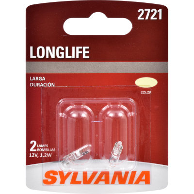
When I left off last, I had the new 250*F limit temperature innards swapped out, and that half of the gauge re-installed into the gauge. We were entering the home stretch. I focused on the bulbs next. There are 4: one each for illuminating the two gauges and one each for the 2 new idiot lights (Alt and Oil). Now, I don't have the light wired at the alternator, but I figured if I could get the gauge-end ready, it would be one fewer thing to fiddle with later. The illumination lights are simple push-and-twist 1.2W bulbs like the others in the bus dash. In fact, they are the exact same bulb. The idiot lights, however, are not like those, nor are they the same size. The alternator bulb is bigger, and the oil pressure light is an odd spade style. As luck would have it, back when I replaced the thermostat panel bulb in Flash, I had to buy a 2-pack of bulbs. That bulb (Sylvania 2721) was a match for the oil pressure bulb socket. Kismet!

Final Gauge Prep - Wiring
With the bulbs set, I shifted to the wiring. There are 4 signal wires (oil temp, oil pressure, oil warning and alt warning). For these, I simply stripped the wire ends. They already have disconnects at the gauge so I could disconnect them later when I pull the dashpod. The other wires (1 ground, 2 illumination and 2 switched 12V) needed a different treatment. In the interest of keeping the dashpod remove-able, I wired the 2 switched 12V source wires into a single male disconnect. I did the same for the 2 illumination wires. To the ground, I attached a female disconnect. Before I moved out to the bus, I fiddled with the gauge to make sure it was straight up/down.

In the Bus
warming up
The dashpod re-mounts similar to how it came out: slide it under the steering wheel from the center, near the stick shift, face down. Rotate the guts towards the hole. With the combo gauge in the third hole, this is a little harder, but not by much. Now, the hard part begins. I started with the illumination wire that was in the bus, cutting the end off that goes on the passenger-side end of the dashpod. I spliced in another wire with a female disconnect on the end as well as that original wire that I had just cut off. This gave an illumination signal that the combo gauge could plug into. Then, I started plugging in all the things that were there before... the grounds, fuel gauge, turn signals, and the low beam / hi beam and, of course, the illumination bulbs. Before I took any more steps, I tested things by turning the key to run, and flipping various switches to see the bulbs light up. Satisfied I had done no harm, I shifted to the new gauge wiring.

I started by inserting one of those "chair" disconnect splitters into one of the dashpod grounds and then connecting the ground wire from the combo-gauge. I then used my wire color map from my last post, heat-shrink splicing the gauge signal wires to the cable wires. Then, I plugged in the illumination male:female. Last, I sourced switched 12V with a covered female disconnect, and plugged in the male from the gauge. I thought about wiring it into the black switched circuit that powers the fuel gauge and the turn signals, but couldn't get my head around how to do it with one of those chair disconnect splitters without risking an accidental grounding. I wanted to minimize the wire cuts too. Last, I could have just put disconnects on the ends of the colored wires rather than splice into the original gauge wires; I just didn't. I still might.

thermostat just opening
The location of the new gauge interrupts the wire-flow for the brake warning light. I will need to extend those wires, or change the warning light location. Since we are still semi-restricted for CoViD-19, I won't be driving any great distance terribly soon, so I have time to resolve it. I found it interesting how much tension was on these wires, though; curious that there was no wiggle room on them. That was true when I went to remove the dashpod at the start of all this as well. Looking back, it was an issue when I went trying to figure out what was up with the fuel gauge years ago. In fact, removing the dashpod this time involved moving the wires one by one through the hole, while placing considerable tension on the wire, so I wouldn't mess up the wires during removal.

Unrelated, the couple of hours I spent in the bus getting the dashpod wired and installed I also test-ran the little heater with the new Afterburner thermostat. Once I had the temperature probe in a spot where it was not up against the outside wall, the thermostat held the interior temperature at a fairly static 70*F. Considering the wind and rain outside, it was really luxurious. Imagine how different the experience is compared to lying in the street gutter trying to get an alternator swapped out in front of that old Lake Oswego house.... in a late fall rainstorm. We've come a long way, Hapy.

Testing
after thermostat opened
With the wiring complete, I slid the dashpod into the hole. I found that the washers that are helping to hold the combo gauge to the dashpod will hang-up on the hole if you are not careful when you remove the dashpod. I will think about how to construct something to hold the gauge on better. Anyway, once roughed into place, the 4 Phillips screws will get it into the right position. Once locked down, I re-tested the system by flipping the key to run. The gauges lifted off of their bottom position just like they did on the kitchen table during the tests. This told me that the round-trip for the 2 circuits was good. Then, I turned on the lights and I could see the gauges illuminated. The oil warning light popped on, but the Alt light did not. This was all as I expected. Next, a test fire of the engine, and maybe a little cul-de-sac parade to get the gauges to move. First, of course, thread the speedo cable into the back of the speedometer.

Because of continued limp-mode issues, I ran my engine-running tests in my driveway. That made the picture-taking possible, though. The gauges respond as I would have expected. The oil pressure starts high when the engine is first started and then settles down once the engine is warm. The oil temp warms faster than the coolant. When I rev the engine up and down, the oil temp climbs and then settles. My last test was to check under the bus for fresh oil spots. There were none. You can see from the pictures what the coolant temperature is (number in lower left corner of UltraGauge).

With that, the oil system gauging is complete. I am not sure what's next. I have a cable for re-wiring the front-to-back stuff, and otherwise I'm just about running out of parts for projects. I do have some coolant hose and a stretch of aluminum pipe, though, so maybe I'll get after some part of the defroster. Of course, some day I'll have to get back to paint-prepping Zed, the 1979 280ZX. I'll figure it out when I get to the garage. Thanks, as always for following along--

Tuesday, May 19, 2020

Oil Pressure and Temperature (Part 5)

When I left off last time, I had a Porche combination gauge fitted to to the bus dashpod in the previously blank third-hole. I had wrangled the stock oil pressure sensor out of the oil filter housing and back into a VDO "T". Into the other side of that "T" I threaded the big dual-pole oil pressure sensor. Last, I removed a M10x1 plug near the oil pressure sensor spot and threaded in a sensor designed to capture water temperatures, topping at 150* (250*F). Today's post continues this saga with a detour into swapping out the temperature gauge innards with new guts from a new VDO gauge.

Wiring Rear
I started with the next obvious thing: wiring up the sensors in the engine bay. First was estimating where to cut the cable. I threaded it through the cable holder on the oil filter and then gave myself about a foot more. With a knife, I whittled the cable casing back to the cable holder. Then, I followed the color chart, starting with the black wire to the temperature sensor. This sensor is less than 4 inches from the cable holder, so while this was easy on the brain, it required some stretching and finger dexterity to cut, strip, attach a disconnect and heat-seal the connection. Once done, I cut the housing on the dis-connect so it could slip onto the stud on the end of the sensor. For the oil pressure related wires, I did not have ring disconnects. So, I will revisit those later, after the CoVid lockdown ends. In the meantime, I simply placed the stripped wires (red and blue for the warning light and gauge respectively) and threaded the cap down on the posts. This will work for testing purposes, but with the shaking that comes from a diesel plus the shaking of driving, one or both will fall off eventually, so I will need to apply the ring terminals.

I left the rest of the cable alone. Back when I was still suffering temperature issues, I removed the engine cover. I decided this was a great time to re-install it. So, with a couple M6 bolts and washers, the cover went back on.

More Gauge Fun
cut line on new gauge
temp gauge removed
The longer I thought about the suitability of the oil-temperature gauge in the combination cluster, the less enthusiastic I became about installing it without trying to do something about it. So, I decided I would hack-up a water temperature gauge and swap the innards with the innards of the combo gauge. My plan was for it to continue to look like the original gauge, but the top of the range would be 250*F, aligning with the sensor. This might have the opposite effect of giving me an "in the red zone" appearance when we're still down in the 230*F range. I think I can live with that, so long as the gauge gives shows a clear difference between 210*F (normal) and 235*F (my believed top end of normal).

So, how do we swap the innards? It starts with removing the temperature section from the combination gauge. It is held on with small slotted screws. Once removed, the unit pops right out. I had an extra new-old-stock (NOS), new-in-box (NIB) temperature unit I got off eBay before I got the combination gauge. I figured I would use that as my transplant target so I can revert back to the original later. I found a few differences between the original gauge innards and the new ones. I will highlight those differences as I work through this.

New VDO Gauge Destruction
old innards top
new innards bottom
At a high level, I followed the Dave Barton PDF process where you cut the housing in half to get to the inner workings of the new gauge. I found that a standard screwdriver was 1/4" thick, so I used that to mark where to cut. I threaded the collar up to that point and then traced around the gauge housing, using the collar as a guide. I taped over the gauge lens with blue painters tape and the cut the line with my hacksaw. As directed in the instructions, I cut just enough to break through and then rotate the gauge housing to extend the gap around it. The top part lifted off right where the gauge face meets the housing. Perfect instructions; nice job Mr. Barton. I also used the salad-fork method to remove the needle, using sparing force so the needle slowly lifted off the little pin. I encourage taking great care on this step.

With the needle off, I removed the small slotted screws on either side and then removed the gauge face. Then, I moved to the flip-side. With a 7mm socket, I removed the nut on the post. The tabs hold the gauge innards in by friction. So, I put the mounting collar on backwards, so I could stand the gauge on its (now missing) face, with the tabs pointing upwards. With a framing hammer, I gently encouraged the gauge innards down by tapping on the tabs and the bolt-post. If you do this take care that the pin the needle sits in does not get crushed or bent or in anyway really touched. It did not take much force to get the innards to move. I held the hammer about 4 inches from the head and tapped.

Old VDO Gauge Mount Destruction
gauge mounting plate
I started with the same process as I had done with the new VDO: salad fork on the needle. This was not as clean a process as it was with the new one. In fact, I would discourage anyone from trying to remove the needle this way if you intend to reuse the needle or the innards. In my case, the needle was damaged, and I was unable to tell how the original needle was connected to the pin. I resolved to using the new VDO needle and kept going. I removed the 2 slotted screws holding the gauge meter / face on. Underneath was a thin piece of dried up wax paper. I carefully separated that from the gauge innards.

With the gauge face torn down, I switched to the mounting side. The old gauge separates from the metal plate fairly easily. With a 7mm socket, remove the nut from the central post/bolt. With a slotted screwdriver, encourage the innards to pull away from the metal plate. It is held purely by friction.

Re-Assembly Preparation
testing old and new together
Now, we have a small pile of parts. From the new VDO innards, the tabs need to be removed from the rest of it. These simply slide out. Now, look at the 2 innards. They look very similar in some ways, but have one major difference on the not-gauge-face side. The inputs are 90* offset. If you look at the old metal mounting plate, you will see that the 4 holes around the central-post/bolt hole are 2 different sizes. The old gauge innards' holes line up with the smaller set and the new gauge innards line up with the larger set. The plastic thing that holds the tabs for the older model has 2 plastic nubs that line up with the larger holes. Those nubs hold the plastic holder and the innards stationary. If you were to cut them off, the gauge would not sit still, and could ground against the metal plate. I hadn't pieced this together when I cut them off in an attempt to get the new innards to mount. I would recommend instead that you expand the smaller set of holes so they are the same diameter as the larger set: so all 4 are the same size. Then, the plastic holder can go in in either orientation. If you hastily cut off the plastic nubs, like I did, you can solve by locating a pair on small plastic finishing tabs from one of those assemble-at-home pieces of furniture. With a little whittling, it can be formed to hold the innards in place. I suggest altering the mounting plate instead.

Re-Assembly
approximately 175*F
comparing top temp
modified on the right
However you solved for the attachment of the plastic bit to the metal plate, slide the new VDO innards onto the 2 posts. There are 2 ways the gauge innards can fit, but only one that actually works. So, when you do this, consider the orientation of the gauge so that the gauge sweep will be on the correct side. Press together firmly. Making sure the ground tab is on the bolt, thread on the 7mm nut and tighten with the socket. I considered the orientation of the new innards on the old plate and marked which side was for the signal (S) and with was for power (+) before I moved on.

If you intended to create your own gauge face, or paste on an aftermarket one, now is the time to do that. I would really like to have markings to show where important temperatures are, but I also like the simplicity of the stock gauge, so I left it alone.

To the gauge face side, I set the wax paper and then the old gauge face. I used the 2 slotted bolts from the new gauge to attach. Last, carefully press on the needle. Once it is all together, it fits back into the combination gauge housing just as easily as it was removed. If you are using the needle from the new gauge, you will need to insert a small washer between the mounting plate and the combo-gauge for each mounting bolt or the needle will hang-up on the contoured plastic near the rear (front is front) of the gauge housing. Using the 4 slotted bolts it was held on with before, mount the plate to the cluster threading each bolt through a small washer. Re-attach the wires.

Setting the Gauge Range
gauge re-installed into dashpod
As you can see from the pictures, I took the opportunity to test the new and old innards with various temperatures. First, I applied an open flame to the sensor to determine the top temperature. I then checked to see where the needles of the 2 different gauges sit when I put the sensor in boiling water. This took some doing since the "kitchen" table is 10 steps or so from kitchen-proper. I would boil some water in a small cup in the microwave and then dash over to test it. As a result, I think the picture on the above right is for around 175*F. If you consider how much gauge is left above the needle for the new innards, and that the top temp is 250*F, I will have a wide band for the temperatures we care about: 190*F to 230*F.

Well, that's an awful lot for this week. All that's left is installing it into the bus. I have to do some wire disconnects, but I don't expect it will be terribly dramatic. Now that I see the gauge in it's final form, I would absolutely recommend bus-pilots who still have their original air-cooled engine to think about installing one of these combo gauges. The original temp range is designed for the air-cooled hot oil, and it looks really good, in my humble opinion. Knowing that the new gauge innards can be swapped in eases my old concerns about long-term support as well. Just get a new VDO gauge (less than $40US today) when one of these fails, and do what I just did.

Thanks, as always for following along. Not sure what I'll work on, much less post on next. I guess I'll figure it out when I paw through my parts and incomplete projects. Stay safe and be well-

Tuesday, May 12, 2020

Oil Pressure and Temperature (Part 4)

This really has been a ton of fun. We have a Porsche combination gauge mounted to the rear of my removed-from-bus dashboard. We have tested the VDO sensors against it and everything seems to line up. So, today we shift to installation.

Cable, Not Wires
inside belly pan
Rather than run another whole set of individual wires, increasing the spaghetti under the bus, I went a different route. In the TDI retrospective (See TDI install retrospective: Secondary Electrical), I mentioned a cable company. Shortly after that, I decided that I would do this gauge thing and use a cable to send the signals from the engine bay to the dashboard. I figured that I had the 3 for the oil system (temp, oil pressure gauge and oil pressure idiot light). I also want to know when the coolant is low and when the electrical system is tanking, like a normal car. So, I got a 6-wire cable, leaving one open for future expansion. Similar to most of the other stuff on this project, I ordered the cable in January before things started getting CoVid-interesting.

Snake-y
harness pops out here 
I want this install to be as clean as I can make it. So, I figured I would route the cable along the same route as the original main harness. Finding where it pops out inside the front of the cab of the bus isn't very easy: it is under the windshield-washer tank. This is much more obvious from underneath, hidden inside the center belly-pan between the main rails. I drilled a matching 11/16" hole an inch or so to the driver-side of the main harness pass-through. From inside the center belly-pan section, I pushed it up through that hole, inside the bus. I then took it from the inside, along the same path as the main harness over towards the fuse box, over the ventilation tubes and up behind where the dashpod sits. I gave myself an extra foot of cable so there wouldn't be stress on it later.

Sending the cable rear-ward was the easy part. From the center belly-pan, I threaded the cable from behind the front axle along the same route as the main harness, meeting it where it emerges from the steel pipe it travels to the rear of the bus. It ran along the main harness pipe, through a small pass-through in the rear cross-beam and back towards the starter. It passes right into the engine bay where the fuel does. I coiled the extra cable there. I had ordered 30' so I had more than enough to run it exactly where I wanted it. I cut off the excess, leaving almost 10 feet of cable, so the total need was just over 20 feet. For my future self, here is the wire color -to- purpose mapping:

Circuit Color Purpose
1 Black Oil Temperature Gauge
2 Red Oil Warning Light
3 Blue Oil Pressure Gauge
4 Orange Coolant Warning Light
5 Yellow Alternator Warning Light
6 Brown open

Pressure Sensors
splitter and stock sensor in
The TDI computer already has an oil pressure signal. It comes out of the oil filter housing. I decided that if that location was good enough for the computer, it was more than good enough for my gauge. So with a 1" spanner (that was the closest I had to the required), I knocked the stock oil pressure sensor free and applied the splitter (VDO 240 850). In order to get the splitter to point the right direction (away from the oil level tube), I added a washer between the splitter and the oil filter housing. If you do this, you may need to do the same. I put the original pressure sensor into the end and the new dual sensor into the split off the side. The dual sensor has a 17mm nut close to the threads, and tightening it can only be done from below, about 30* at a time. Fun.

Temperature Sensor Stuck?
Between the insertion of the original pressure sensor and the new dual-sensor, I went after the temperature sensor. Why? I realized that once I had the dual pressure sensor in-place, I would have my access and vision blocked by it. The plug in the oil filter housing was on fairly snug, but a pop with a ratchet holding a Torx socket did the trick. I don't remember which size; my apologies for not writing it down. Once free, oil seeped out of the hole, even though I had drained the oil before I started with the pressure sensor. No matter. It just made a mess. I first tried with the longer temp sensor (VDO 323 423), but found that it hung up on something inside the housing. I was barely able to get it back out again, and after looking at the sensor after I removed it I concluded that it was not a good idea to use that sensor here. I put a picture of it down below on the right.

Temperature Sensor, Take 2
temp sensor in
I cleared the hole, and checked for depth with a small screwdriver. It seemed like the sensor should have fit, but there is no doubting the compressed look of that sensor. So, grateful I had the shorter, but lower max temp sensor, I considered the impact. Consider that this is not an air-cooled engine, whereas the Porsche combo-gauge came from one. Also, the oil and coolant exchange temperatures, cooling the hotter oil as they do and that cooler oil is what is passing through this part of the housing on it's way back to the engine. I did a quick survey of posts about oil temperatures of TDI's and even the guys who run 'em hard say their temps don't get above 230*F. In fact, most of the folks out there pose that temps above 250*F would be cooking their engines.... and these folks have a sensor in this location, so the plan is holding, so far.

them bumps aint right
So.... I decided that this sensor is probably fine, especially for the short run, while I figure out if this is the long-term solution. Key to this thinking, is to remember that the gauge is to help identify patterns and trends. Also, to remember that this is the temperature as it is re-entering the engine. So, this will be a delayed signal of a climbing temperature event. In fact, it could be masked if the coolant is effectively pulling heat out of the oil. Concluding that I'd come this far and that there was not a better port to test temperature anyway, I continued. The shorter (250*F / 120*C max) sensor threaded right in with no trouble. I lightly torqued the sensors, filled the engine with oil and called it a day.

Wait a Minute...
One nagging thought I have about this is the numbering, or lack thereof, and the red zone on the Porsche combination gauge are completely out of alignment with what I would be concerned about as I drive a TDI. These numbers ("normal" between 194*F and 248*F) are way to broad. AND, regardless of which sender I use, the red zone starts outside the top end of it (at 302*F?). So, I may need to change that gauge at some point if it is really going to be useful long term. I mean, honestly, if normal is around 210 and getting too hot is 230, I will not easily see the difference on that gauge.

Well, that's it for today. All that remains is everything else. I will work on getting the engine-compartment end of the wiring done next. Then, I'll see about getting the dashpod wired and re-installed. Depending on how exciting and time-consuming those are, it could be one or two more posts before I have oil instrumentation.

Thanks, as always, for following along. Be safe, be patient, and if you can, patronize your favorite restaurants with a go order. Now more than ever, you can vote with your wallet for the businesses you want to survive. Personally, Amazon doesn't need my money; Discount Import Parts (now only on the east side) and the local mom-and-pop grocery do.

Tuesday, May 5, 2020

Oil Pressure and Temperature (Part 3)

Hapy cinco-de-Mayo. My last post ended with some testing of the Porsche combination gauge with the modern VDO sensors. I'll pick up where I left off.

Where Were We?
Porsche combo gauge
After I wrote all of those posts about the TDI install, I realized that the little UltraGauge does not show my oil temperature or pressure. I can see the coolant temperature, though. When we drive up a long grade, we can see the coolant temp climb, and I wondered if the oil temperature was leading that charge upward, dumping heat into the oil:coolant temperature exchanger. So, I started collecting sensors to compliment the gauges I had lying around from back when I had the original air-cooled engine and thought that having an effectively oil-cooled engine without a gauge about oil was just silly. That's especially true when that engine was 5 meters away. In my usual fashion, I can't just run wires from sensors up to the dash and stick a couple gauges in back of my windscreen and call it good. Oh no. That would just be too easy. Instead, I got this notion that a combination gauge from a 70's-era Porsche could fit into the 3rd hole in a VW bus dashpod. I was right. But, does it work with the new VDO sensors? Why, yes it does.

Simple Initial Testing
I did some very simple tests of the sensor-to-gauge circuit in my last post. All I did was demonstrate that the gauge would respond to 12V, and if I had a sensor hooked up, the gauge would lift slightly off the bottom post. This is no casual "who cares" moment, in my opinion. Most important, this indicated to me that the big circular thing that I had shipped halfway around the world had operational gauges. But, would they respond correctly to real-world input from modern VDO sensors?

Temperature
water still steaming, needle at 9:00
Testing the viability of the oil temperature circuit was fairly easy, once I had the circuits set up again. While Boo loves me, I still had to tear down the tests for dinner. So, things needed to be set up again. This time, I included a small glass cup and a meat thermometer. Into the cup I set the sensor, wrapped with a grounding wire with a sender wire on the end. With the circuits powered by a big auto battery, I poured boiling water into the cup. The gauge moved from pointing down to 9 o'clock (correct for water boiling-point) which should be around 210*F. I thought I could confirm the test with the meat thermometer, but instead I found that the meat thermometer was not correct. How fun! In subsequent tests, I discovered that the probe on the meat thermometer needed far more surface area to reach the correct temperature reading. So, rather than triangulate on the proof that 9 o'clock means 210*F, I learned that my meat thermometer reads cool unless at least an inch of it is inside the target. Good to know for future baking. Anyway, this test passed.

Pressure
decoding the no-number gauge
Testing the pressure was not as fulfilling as testing temperature. For temp, we know the boiling point of water so if the gauge doesn't rise to halfway, then we would know that the sensor is on a different resistance gradient than the gauge. That would have been a real bummer. For pressure, I needed to depend on my Mity-Vac. The Mity-Vac has already proven its worth of the years as I have tried to bleed brakes and pull fuel through lines after running the tank empty (I know; bad owner). It also has a pressure setting though. With the circuits wired up, I set to it. I keep a short stretch of fuel line in my Mity-Vac kit, and that fuel line is the perfect size for the threads of the pressure sensor. I threaded one end onto the sensor and put a basic auto-adapter from the Mity-Vac kit in the other end. To that, I connected one of the short clear lines and then the Mity-Vac. This set up allowed me to send a pressure signal to the sensor. I jammed the grounding wire between the end of the fuel line and the sensor housing on the threads (establishing a viable ground) using that friction to hold the wire in place.

around 15 psi and around 1 BAR
Once everything was powered, I simply applied pressure with the Mity-Vac and watched the needle rise off the post. Translating "Druck Pressure" to PSI is a brief exercise in understanding German. Druck is effectively barometric or BAR and 1 bar = 14.7 pounds per square inch. So, to confirm the gauge is operating correctly, I needed to get "Druck" = 1 when I had just shy of 15 pound of pressure on the Mity-Vac. That succeeded: the needle on the gauge climbed to 1 and then slowly dropped as the pressure was slowly released, matching the needle drop on the Mity-Vac. I would have liked to have proven the mid-range of the gauge, but the Mity-Vac and my cobbled-together plumbing couldn't handle more than 15 pounds of pressure. I thought about getting my air compressor involved, but concluded that the test was already successful.

Conclusions
So, what did this tell us? That sensors bought today will correctly align with a gauge pulled from an old Porsche. We demonstrated earlier that the gauge would fit in the spare or "third" hole. I think we have a winner and I'm beside myself with excitement about it. I will clean everything up, replace some bulbs, run a wire bundle, and road-test everything, etc. when I have some time outside with Hapy. You can see in the pictures on this post taken during the tests that the gauge now sits nicely centered in the hole. I think it looks fantastic, but it's my bus, so its my choice. Knowing that I will have visibility into the lubrication system, and can start analyzing whether the oil temps are leading the temperature increases on long climbs is pretty exciting.. for me anyway. If my theory is proven, I can start looking into improving oil temperature management so climbing hills or mountains eventually have a much reduced impact on engine temperature. First, we need to see the data.

Thanks, as always, for following along. More next time-

Tuesday, April 28, 2020

Oil Pressure and Temperature (Part 2)

In my last post about adding gauges, I suggested 6 possible alternatives. Today, I focus on the viability of option 5: fitting a Porsche combination gauge into the spare hole in the original bus dash pod. I do want to stress that I bought pretty much everything for this project before the end of January, before we knew what this CoVid-19 thing was about. The only exception is the oil temperature sensor. I had purchased the wrong one (English threads not metric) long ago so I needed to get one that would actually fit. On with the post...

Porsche Combo Gauge
blank held up by napkin-holder
First, we start with the question I've been dying to find the answer to: will a combination gauge from a Porsche fit well enough into the third hole on the bus dash to provide oil temp and pressure information? The short answer, I think, is "yes". I'll pause for a second to let that sink in. Yes, that gauge will fit. But, will it look good and do we need to do anything to the dash or the gauge or both to make it fit? Ay, there's the rub. In this case, quite literally... there's a rub. As in, the left-most edge of the combo gauge rubs against the large plastic column in which lies the speedometer. Could it get wedged in good enough? Sort of, but it would look pretty janky. So, could we shave off some of the outer edge of the combo-gauge to make it fit? Maybe. Alternatively, we cut a small section out of the plastic column, and have the combo gauge nestle into the small section. Either way, something needs to be damaged to further the investigation.

almost exactly 4" diameter
the original blank 3-5/8"
So, what's to do? Well, it turns out, my dash-pod, dash board or whatever you want to call the plastic thing that is held on with 4 screws, is cracked. In fact, there is a break running from the bottom edge of one of the climate control sliders all the way through the bottom of the dash-pod. And, the upper left corner is broken off. Cosmetically, it really should be replaced, but it does hold to the dash, and hold the gauges well enough. When I contrast it against the nearly flawless Porsche combo gauge, it seems rather obvious to me which one should be sacrificed to learn how to make it fit... or if it can fit: the cracked and flawed dash.

Before I start pulling out the dash, it would be wise to take a bunch of measurements. I took pictures of them so others can see how close everything is before I touch anything. This includes a test fitting in the cab of the bus. The pictures are strewn across this posting.

Pull the DashPod
combo gauge with glass
from blank on top of it
The dashpod is held on with 4 long Phillips screws. Remove them and stow them safely. Then, reach behind the dash and un-thread the speedometer cable from the speedometer. If you have the plastic tips on your climate control levers, remove them. Now, you can lift and tilt (top downwards) the dashpod so you can get to the wires behind. I can't stress this enough: do NOT just start pulling wires. Identify each one and label it with a toe-tag, a piece of folded over tape, whatever it takes so you can correctly put it back in at the other end of this exercise. Move slowly, be patient. The slower you go now, the more you will appreciate that you took the time at the other end. Once all of the wires have been individually labelled and removed from the back of the dashpod, you can remove it all the way by sliding it towards the center of the bus.

Measure, Check, Measure, Check then Cut
Even though this dashpod is cracked and will be replaced, I have no idea when I could get a replacement. Worldwide commerce is slowing to a crawl, my favorite parts places have been sending notices that they are shutting doors until further notice, etc. So, even though I expect to replace this dash, it could be months before I find a viable replacement. So, I will treat this exercise as if this is the only dashpod in earth.


test fit cockpit side
test fit from "above"
The picture on the right, here, shows where the interference points are. First, at the bottom of the photo you can see that the black ring around the Porsche combination gauge hits the side of the speedometer section before it can fully settle into place. This uneven look can be seen through the rear (front-is-front) of the dashpods in the picture on the left. It may not be obvious, but the oil pressure gauge is slightly less visible than the oil temperature gauge. The two idiot lights should be in the exact left-to-right center of the circle, but they are offset to the right. What cannot be easily seen from any picture is that the edge of the gauge hangs up on the little plastic tang between the threaded hole for the screw and the edge of the gauge hole. I started with those: I cut a shallow channel in-between with a hacksaw.

hole cut in speedo side
trimmed backing
Once I could get the gauge to settle in, I could mark where to cut into the speedometer slot. I covered the area with blue painter tape and marked up ideas with a sharpie. The hole ended up less than an inch from gauge top to gauge bottom and less than 1/2" in depth. It is oriented just below the edge of the outer gauge ring so the combination gauge can slot in. Ultimately, the gauge does not need much space, but it needed a little.

Last, the metal backing plate on the original dashpod needs a trim. It is not as obvious in the picture, but that slight overhang is enough to knock the combination gauge off-center. I marked the short (about an inch long) stretch that needed to be removed along the edge. With tin-snips, I cut that section out and then refined it with a file until the gauges could nestle together. Now, the backing plate threads back on without pressure and the combination gauge sets perfectly centered.

Gauge Wire Identification
labeling wires
If you are thinking of doing this, I strongly suggest that you verify the combination gauge you acquired still works before you grab a saw. I found this kind of fun. The gauge that I was shipped was removed from a late 70's Porsche and then the wires were cut. This is important because I would have had much more research to do had the seller pulled all the wires off. Now, there was a strange green over-spray on most of the wires, so my identification instead was based on what they were plugged into. Similar to the wires removed from the old dash on removal, I labeled these wires as well. There were 2 circuits of particular interest: brown and blue with green dashes. These were the ground and switched 12V respectively. These 2 circuits wired multiple things together, and in the case of the blue/green wire, it had 2 open ends. I think that is to prevent one failing gauge to eliminate the viability of the other. Once these were identified, the signal wires for the various gauges and idiot lights were easy to identify. I removed the gauge lights, after I demonstrated that the ground wires were also grounding those light sockets.

Validating the Gauge
testing oil temp gauge
Now for the fun part: testing the gauges. I grabbed an extra deep cycle battery I had in my garage, and set it on a grub-towel on my kitchen table. My wife loves me. To the positive side of the battery, I connected one blade of a 3-amp bladed fuse. To the negative side, I connected a 16ga blue wire and connected the other side to the ground wire from the gauge. I took a long 16ga yellow test wire which had a female disconnect on one end and bare wire on the other. The disconnect end fit properly onto the open blade on the fuse. I touched the wire to the 12V switched and the gauge clicked, sending the oil pressure gauge to the top. I figured this could be a bad thing, but, undeterred, I removed the wire from the fuse blade and went looking for my senders. I figure this behavior could be a way to signal the driver that there is no longer any signal coming from the oil pressure sender, since I did put the power on the oil-pressure switched 12V side.

combo-to-speedo "front"
I started with the oil temperature, after that odd reaction the oil pressure gauge had to power applied. To simulate installation, I ran another ground wire from the pre-existing blue one around the threads of the sensor. I then ran a jumper from the sensor signal to the temp gauge input. When I applied 12V to the switched circuit, the temperature needle moved off of the bottom post. It wasn't much, but that told me it was reading something. Considering that a success, I did the same thing with the oil pressure sensor. This time, instead of leaping to the top of the gauge, the needle lifted just a hair off the bottom post. Again, I took that to mean success.

I am concluding that the modern VDO sensors will activate the original VDO gauges. I need to conduct further tests, but this post has already gotten really long. I'll post on those tests next time. And, I'll post what the gauge looks like after all the trimming.

Thanks, as always, for following along. I must admit, if you are looking for a can't-leave-home project, this one has been a lot of fun. Please stay safe, and more next time-