Showing posts with label electrical. Show all posts

Tuesday, January 9, 2024

Furnace Finished

Today's post covers the final steps of completing the furnace in the NewOldHouse. In my last post, we had cut the hole for the intake and lined it with venting. Our no-longer-an-HVAC-guy electrician was coming over to test the system so I needed to solve a couple of things first. Like the exhaust venting.

Exhausted
operational furnace
When I disassembled the furnace last summer, I saved all of the exhaust venting. I figured I could reuse all of it and but whatever pieces I needed after that. When I did my test fit to confirm the angle (minimum is 1/4" per foot or 1" per 4 feet, I did 1" per 3 feet so better than minimum), I determined that I had more than enough pieces, but did not end-to-end assemble it. These double-walled vents are built to twist-lock and they only assemble one way, indicated by the arrow on the sticker on the side. They are kind of like big-boy Tinkertoys. The sections which can turn are an engineering marvel. They can be twisted into all kinds of off-set shapes or simple angles to get the venting to go where you need it to. My needs were simple, however. From the top of the furnace, I turned it 45* towards the chimney, ran a straight segment and then another 45* angle to head straight into the chimney clear-out hole and the liner contained within. I had retained the collar that threads onto the liner and rests in the brick and I had retained the connector at the end of the vent that abuts the collar, and it tightened down with a set screw. I had expected a couple of hours, and assembly of the chimney was less than an hour.

Using stainless steel pipe-hanger strapping, I suspended the chimney from the floor joists in 3 spots, all closer to the chimney than the furnace. I recalled from my angle testing that I needed the exhaust to enter the chimney near the highest point in the hole. So, I started there, pressing the vent up against the hole, and then worked towards the furnace from there. I used screws instead of nails so the straps could not work their way loose from vibration. Before crawling out claiming victory, I grabbed the cloth webbed strapping that I used to suspend the HVAC and supported the gas line from the floor in a similar fashion. Like the exhaust vent, I do not want the gas line to shake itself loose, potentially creating a leak. I chose to use the fabric webbing instead of the stainless because I thought steel-on-steel could either create a spark or slowly cut into the pipe. Cloth don't cut. Content, I contacted our electrician to test things.

Furnace Active
suspending the vent
Our electrician connected the thermostat to the control wire (which was just run out through the big hole in the floor) to test the system. He knew the state of the gas line, the electrical, etc, so I wanted him to run the test. Besides, I wanted a final review of the work too. The review was quick and positive, so he started a test.... shazam (not boom) we have central heat. While the cold air side of the furnace is just an open plenum reaching into the crawlspace, the test was successful. We ran the system for a bit while he checked for leaks and CO. Everything came back perfect, so we just let the furnace run and bring the temperature of the house up from 58*F to 68*F (14.5C to 20C). The following weekend, I returned to the cold air intake.

Return to the Return
With the furnace operational, I could get back to the intake with a little bit of time flexibility. I had the start of the intake from the floor side and I had the plenum jutting out from the intake side of the furnace. I just needed to connect them. I started with what I thought would be the hardest part: the sides from the plenum to the intake. In retrospect, I probably should have started with the floor of the floor-side to keep it square, but it's done now so who cares. Because the furnace is not 100% square to the house, the sides were not exactly the same length. I cut them the same though, so the south side is a little longer, jutting into the floor-side box by an inch or so. Regardless, the installs for the 2 sides were the same: I set the plenum side into the S-clamp, screwed in 2 sheet metal screws and then attached the other end with another pair of sheet metal screws. I shifted to the top and bottoms next.

Because the floor-side is not aligned with the plenum, the top and bottom were parallelogram shaped, with the ends measuring 20" and the sides at a angle around 45*. Again, because the sides were not exactly the same length, one cardboard template did not suffice. In the interest of conserving materials, the top was completed with multiple smaller sections and then seam-taped. The bottom, however, is one shaped piece added after the floor of the rectangle intake was in place.

Last, I got to the rectangle at the bottom of the intake box I built earlier. For this "floor", I cut another piece of sheeting 23 inches long by 16 inches wide and cut 1/2" notches out of each corner. 3 edges were then bent 90*, leaving the edge facing the furnace flat. I set the floor in from below, sealing the seams with tape, before shifting to the bottom of the intake-to-plenum connector.
 
Filtered
I had intended to get clever with brackets and such to hold the filter in place. I abandoned that simply because I ran out of give-a-shit by now and simply wanted filtered air. Since the south-side ran long into the airbox, that provided material to hold the upper corner of the filter. Using a filter to guide the shaping, I bent the overhang into a tang to hold the filter. The other corners simply stay put, and the 16 x 20 opening is perfectly covered with the filter.

where we started
We have been running the furnace since the filter was added and the air in the house is steadily getting less dusty. After all the work that's been done around here, the dust has been considerable. We have run a small portable filter, but it has not been as effective.

Well, that's the end of this epic effort. For a timeline, the furnace was disassembled in August and moved in September, the chimney repaired and lined in early October. The crawlspace patio was dug out, graveled and patio-blocked in late October; a stand attached and the furnace secured in early November. Air distribution was disassembled, cleaned, reassembled and insulated from mid November to early December. Everything else was crammed into the following 2 weeks. This job was quoted to me for $10kUS. If I paid myself $100US per hour, I still would have paid the HVAC company more for this.
 
This effort took place around a music festival, a family wedding, multiple holidays, kitchen planning, prepping and seeding a lawn, gigs, jams, love and life, and of course, my band (shameless plug: Sunkicks) recording, tracking and mixing an EP (release date 2024-Feb-2). Life is full. I expect there will be more construction posts, but Hapy needs some work done so I expect there will be a post or 2 on that, once I get to it. Thanks for following along-

Thursday, December 28, 2023

Dashing Thru the Smoke

After returning Hapy to service, I have not driven him much. As has been true for most of the time we have been together, he doesn't have heat. So it's like driving in an ice fishing shed... which probably brings some appeal to some folks, but it's not my favorite. Still, if I had to get somewhere and I could get there without using freeways, I would and have drive(n) Hapy. Why not freeways? This time of year, as I am sure you have noticed, drivers are especially distracted and others are driving specially, uh... nasty. This old bus needs more braking space than modern cars but other drivers don't always recognize that. When you add those factors together, it is tough sledding in the bus. Add in wet or slick roads and it gets scary. Regular roads are bad enough, but freeway speeds are too scary in the winter for me and the bus. With this backdrop, I start today's post.

Smoked Again
can you spot the loose wire?
A few years ago, on the return drive from 4Peaks, we were greeted with smoke billowing out from under the dash (See 4Peaks 2018 - Road Report). Somehow the ignition sub-harness had fried, leaving us stranded, riding home on a flatbed again. There's a song lyric in there somewhere. Anyway, I fixed that once and then again in a not-to-my-best-liking way with now 2 keys to operate the bus: one to unlock the steering and one to start/run the engine. This is working well enough so I leave it alone.

The other night, I had to drive out to Hillsboro for a final recording session with the band I'm playing in (shameless plug: Sunkicks), and Boo had not returned from work. So, I pressed Hapy into service. With the new starter and better glow-plugs, he fired right up and hummed like he was ready for some fun. It was damp out, so the lack of heat meant drying the inside of the windscreen with a towel, but for the ride out, it only needed that one wipe down. Even the driver door closed without too much trouble. It was like Hapy was really trying his best to show he was a real car and could be used reliably. We stopped for some home repair parts at the big box home repair store and he started right up afterwards. Again, "I'm a real car".

After the recording session concluded, the temperature had continued to drop, while the moisture held steady so the interior glass was quite foggy. Hapy fired right up and I flipped on the running lights while I refamiliarized myself with the controls in the dark. I thought I had the switch for the fans in my hand, but it was actually the headlight control... I turned hard it to the right (the fan control switch has always been a little resistant), and rather than turn on the fans, I caused something to ground, causing a wire to release it's smoke. When I saw the smoke, I turned the switch back left (anti-clockwise) but the damage had been done. All that was left was to figure out how widespread it was, and to apologize to Hapy; this wasn't his fault, it was all mine. The smoke was pretty bad though, considering the windows were closed, the bus wasn't moving and the fan wasn't on. The next day, my throat was still sore from it. When I opened the driver window, it must have looked like a scene from Fast Times at Ridgemont High with the billowing smoke rolling out.

dripping blue
Starting with the positive... the engine was still running. The cooling fans were on and could be turned on and off. The defogger (doesn't defrost, hardly de-fogs) fan could be turned on and off. As to the negative, the driving lights were out, I think the tail lights were out and there was an annoying buzzer like a seatbelt warning was on. When I flipped the turn signal or hazards, the front lights flashed correctly and the buzzing went away. I was still sitting, idling in front of my bandmate's house, so I decided that I would just drive home and deal with it later.

The drive home was quite uneventful other than the constant buzz noise and concern that drivers behind me could not see us nor tell when we were braking. When I got home, the engine and fans shut off without issue. It was too late and too dark to diagnose, but my hunch was that it's the wire that sends a signal to the running lights.

Wire Still a Puzzler
A few days later, when I could go out to the bus in daylight, I went out and removed the headlight switch from the dash. I could see one of the wires had become detached, but I was unable to see any truly fried wires. Puzzled, I plugged the wire into the open pin on the back of the switch, and tried the lights. Yep, headlights still turn on, dash lights still turn on.... running lights turn on. All of them, including the tail lights. So, I pulled on the hazard switch. Dash directionals flash, front directionals flash, rear directionals flash. At this point, I don't know what's fried, but the engine starts and runs, the cooling fans fire, the dash lights, switches and gauges work and all the lights work. In the middle picture, just above, there's a light blue orb thing on the lower left side of the image. That is a blue drip that I cannot account for, but I think something melted and that's the result. Neat.

I think it is time for me to determine which of the original circuits no longer need to be served and at the very least remove the fuses. After the cleanup I did in the back for running the engine, I think it would be wise to plan to do something very similar up front. I mean, in the end, the only things the "main" fuse box is running now are the dash, and the lights. That's like, 4 fuses tops? Regardless, this exercise should lead me to the smoked wire and reduce the electrical gremlins.

Furnace Update
furnace control board
Our electrician is semi-retired. He used to run a HVAC company and has installed literally hundreds of furnaces before focusing on general residential electrical instead. Now, as he is slowly divesting of his electrical business, he has observed my work on our furnace. In a fit of holiday fever (he swore off furnace work years ago), he popped by for a couple of hours, got the gas line hooked up and leak tested as well as the 110V electrical feed completed, with a worker shut-off switch. He even got most of the exhaust venting put in. He hit a wall when he was unable to connect the control cable because the access screws are hidden behind a panel that you can't get to once the first piece of exhaust venting is attached to the furnace. That's some poor design.

Still, I saw the furnace project as 7 big individual efforts: demo/move/mount, conditioned air distribution, cold air return, gas, electric, exhaust vent and the thermostat/control cable. I had completed the first 2. He knocked down 2 more (gas and electric) and set me up to get the next 2: thermostat control and exhaust vent. Once I have that done, he will confirm things, and test the system. Then, I just need to get the cold air to pull from inside the house and we have a complete system. For testing purposes, I may simply smack a filter on the plenum.

Since I started this thread, I caught a cold, celebrated Christmas and installed the thermostat control cable. As I indicated, I had to remove the exhaust venting all the way to the firebox before I could remove the panel which covers the control board. I ran a new wire from beneath the furnace (where the old one entered) and connected the control wires. Before putting everything back together, I took the opportunity to spray the snot out of the control board with a can of computer-cleaning compressed air. I figured that panel won't be coming off anytime soon, so may as well get the board as clean as I can. After that, it was simple replacing that which was removed, re-using the same fasteners.

That's about where things are today. Hapy appears operational, and I will be test driving him here in the next couple of days. The furnace is almost ready to test. I need to complete the assembly of the exhaust vent and properly suspend it from the floor to retain the correct exit angle, but I think that is a couple of hours effort at most.

Thanks as always, for following along. Have a peaceful, pleasant, hapy new year-

Tuesday, April 5, 2022

Ceiling Wiring Rough In

With the interior of Hapy (1972 VW camperbus) pulled apart for noise control, it was a perfect opportunity to improve some of my earlier wiring decisions. Today's post covers the changes for the wiring that runs in the ceiling. There will be more posts on other parts of the electrical system later.

AWG
I think the first thing to consider when it comes to wiring, is what gauge wire to use. Most of my runs will be less than 5 meters, and very few, if any, of them will require even 10 amps. With this in mind, we consult the chart, and see that 14 gauge AWG (American Wiring Gauge) wiring would meet the need. I rounded up to 12ga and I bought a bundle. This bundle was 12 separate colored wires, each 25 feet long. Most of the wires will be feeding lamps, which draw, like, 1 amp. So, even if one run actually runs the full 25 feet, I am not terribly concerned about the wire health. In fact, I could add more lighting sources or an additional appliance (USB charger, eg) without really jeopardizing the wire health. Similar to car wiring, I set a color so I would know from looking at each end what it was for. The prior wiring had some joint bits in the middle so it might have started one color (most of the wires were red because I had a lot of it), but may have changed in the middle somewhere. That is an impossible state to trace, and I would have deserved a "DPO" label had I left things that way. With the new color scheme, I can be sure I have the right wire in hand. When combined with a fuse chart, following, fixing and effectively owning the wiring will be much easier.
 
I call out "AWG" because there are many vendors on the interwebs who will say their wire is "12 gauge", but not all gauges are alike. Their 12 gauge might be the AWG equivalent of 14 or even 16 AWG. One other consideration: copper coated aluminum wire is not the same thing as solely copper wire. Use aluminum, and/or a too-thin gauge and your vehicle will have a serious fire hazard. I encourage buying the right gauge or thicker and only use pure copper. It costs more, but the peace of mind is worth it.

What Where
I have added electrical stuff all over the place over the years in a thoroughly hap-hazard way. I considered each of them, plus I want to add some things. I have been wanting to improve the lighting for quite a while. We had the original dome light between the seat-backs, but it really doesn't provide enough light into the cab to be useful. So, it really doesn't get used. The light in the pop-top is great, and we use it fairly often when we are set up to camp. We also have the 1979 Westy 2-way light, but when I installed it, I put it where the old 1972 interior light was because it covered the hole in the wood headliner. This placed it off-center of the window which is really only an issue aesthetically. Similar to the pop-top light, it gets regular use when camping. There is no light further back into the sleeping area, and there is no light near the sliding door. With the re-wire, I intend to address all of these things.

To replace/improve the cab lighting, I will install a new dome light closer to the front of the cab. To create some lighting in the sleeping area, I will install a switchable light fixture on the rear ceiling. This light will also double as a light-source for the engine bay. Last, the 1979 Westy 2-way light will move a little further forward for aesthetics. In it's old location, it cast a shadow in front of the fridge cabinet. In the new location, the floor in front of that cabinet will be well-lit, without losing lighting into the fridge cabinet.

Last, the original dome light is getting moved to the ceiling near the front of the sliding door. So, when you open the slider, there is a low-intensity light we can flip on. This will help us getting in/out of the bus when it's super dark out. This switch has 2 positions (I'm calling them switch 1 and 2) originally designed so you could switch it from door operated to off to manually operated and back. In my implementation, switch 1 will turn on the original dome light as well as the dome lights I have mounted in the cab and in the sleeping area. No, the switch was not originally designed to do this, so I am modifying it. I'll post on that later. Switch 2 will only turn on the light by the slider. I thought there would be times when lighting up the entire bus from one switch might be useful.

The circuits, or should I say 12V consumers, I am considering from front to rear. I'm using letters so I don't pre-dispose myself on fuse numbering:
wire hole from above
a -* (grey) cab 12V accessory plug
b -* (purple) new cab dome light
c -  stereo <- will probably leave as-is or run under the floor
d -  amplifier for stereo - not wired yet, would probably follow stereo wire
e -* (white) original dome light switch 1
f -* (pink) original dome light switch 2<- will share pop-top light wire
g -* (pink) pop-top light
h -* (blue) 2-stage westy light
i -  furnace
j -  12V accessory plug by slider door
k -* (green) sleeping area dome light
l -* (orange) sleeping area USB charger ports - to be figured out

*: ceiling wired (wire color)
 
In the past, I had 3 wires running through the ceiling, but it was a total hack. I sent the wire bundle inside the Baltic Birch drop ceiling to the rear driver corner where it basically just dropped down along the inner wall, behind the rear-most window to the floor. From there, it ran forward to the fuse box under the rock-n-roll bed. This worked, but it looked pretty bad and the wires ran probably 5 meters longer than a direct path would take. And, I would catch the wires when loading/unloading gear. With the drop ceiling removed, I could see where the original VW/Westfalia wiring had been run along the top edge where the side wall meets the ceiling and it led me to my improved solution.

Implementing
original dome-light mount

The rear side of the B-pillar (directly behind the front doors) is hollow. In the top edge where stock wiring runs, there is a factory hole from the edge into the B-pillar. This is probably intended to route a sunroof drain or something. I used it to route the wires from the ceiling down along the front edge of the middle window and into the dead space under the window usually hidden by a door/body card. From there, the wire bundle runs rearward and around the old fridge cabinet to the fuse-box under the rock-n-roll bed. This path is considerably shorter, which reduces the opportunity for a wire to short as well as reduces the drop in amperage between the battery and the appliance simply because a shorter wire experiences less loss. I ran the wires one at a time, from below upward. I threaded the first wire by chasing bailing wire down from above first. To that wire, I duct-taped my first wire. Once it passed through the hole, I duct-taped the next wire to the first, and sent it up and through. I repeated versions of this until all 7 wires had passed through. I am not sure there is still room for another wire, if I need to send another, like, for the ambient temperature sensor for the furnace thermostat.

One point worth highlighting: all of the wires are intended to serve a single consumer except the dome lights. The pink wire will support the pop-top light and the original dome light when only that light is turned on, which has moved above the slider. I moved it because the most frequent need for light is when we enter that door, so having a switched light right there will be very useful. Why share? Neither light will draw much, and even if they are both on at the same time, the draw will be well below the limit for the size wire. The same goes for the other position (white wire), since those dome lights draw so little. Besides, that B-pillar pass-thru hole was getting crowded and the number of isolated wires is probably already overkill. When I think of how many fuses there are for the entire electrical system for Oliver (1978 MGB), this plan really feels like over kill.

At this point, I have not yet tied the wiring into the fuse box. Since I will be addressing the fuse box, luxury battery and, maybe, the old fridge circuitry later on, simply having the wires snaked from their termination points was sufficient. Let's call this the "electrical rough-in".

Well, that's it for today. This took me an entire weekend day just to get this far, though I also removed all of the old luxury wiring and that takes a little time too. I accept that I move slow and quality... well, snaking wires... takes time. Thanks, as always, for following along-

Tuesday, December 15, 2020

Chasing the Hapy Electrical Gremlins (part 3)

Continuing on our journey through the darkness of the wiring rat's nest.
 
Shouldn't Have Cut That
not quite "before",
dashpod already pulled
I'll just jump right into the interesting part. Well, mostly. I started in the engine compartment and removed the wiring related to the coolant heater first: the relay box, the wires down to the glow plugs, etc. That much was great. Then, I moved on to looking at some of the wiring above, and as the bold-faced line implies, I cut something I would best not have.
 
Reflect back to the last time I clowned around on this wiring, I dug deep into the fuse-box. I started by pulling the fuses for circuits Hap doesn't need. Circuit by circuit, I cut that unnecessary wiring by referencing fuse sockets where the fuses had been pulled. That plan worked great. Lots of extra wiring got removed, and the engine still ran. I still had the sporadic not-limp-mode, and the occasional Hapy-don't-wanna-start issues, but they both seemed improved. Well, this time around, I got into the fusebox and saw a few wires that did not appear to have a partner on the other side of the fuse. So, I figured I just missed them the first time, and cut them. Well, that was wrong. Their "missing partner" was actually a common-line always-hot (circuit 30 in VW-speak) that was kind of hidden from view. Well, I didn't see them anyway. The wires I cut are for powering "engine control" circuits, of course. So, kinda important. Ugh.

Fuse Box Smaller
don't actually need
any of these relays
Once I realized that the wires I cut were critical, I needed a new plan. A while back, I bought a small relay box thing off eBay that has 6 relay slots and 6 fuse sockets. Once it arrived, I looked at how many fuses were in the donor fuse box and how many sockets were in that smaller box and the math did not add up. That was all before I did the clear out I mentioned above. After that, I was down to 7 fuses, and one of them was for the OBDII plug that I don't actually use. So, I think the fuse socket numbers may work. As for the relays, I only need 2 of the donor relays: the infamous 109 (main power) and old 180 (glow plugs). All the other ones can go, which leaves me 4 slots for other things, like the "RUN" and "START" trigger relays I have connecting the ignition from the front to the electrical from the donor. Neat. I didn't mean to change the fuse box and the relay plastic holder thing, but when I cut those two engine control wires the die was cast.

Label, Label, Cut
smarter way to remove
extra wiring
So, into the darkness we go. I started with the more obvious wires, like the thin little wires on the 180 (glow plug) relay. Then, I moved on to the T10 plugs. There are 5 (Blue, White, Black, Orange and Brown) 10-pin plugs in the mix of all that rat-nest. I unplugged them, and started dissecting by labeling either side of the cut, describing what is on the other side, and cutting. This picture on the right here explains the wire coming from the ignition switch position 86s as an example of how I dealt wit the wire-snarl.

While that sounds like quick work, I have moved slowly, researching each wire first, to make sure I don't have another "engine control" mishap. And, I want to do more than just label where it went; I want to know what it does first. This is a lot like a jigsaw puzzle where the more you do, the faster it goes until you eventually have all of the wires you intend to cut labelled and cut apart. I am almost done, which means the next post on wiring should include some building back up.

Diagramming
One last thing I have been doing, is crafting my own wiring diagram. I started by scanned the wiring diagram for the early ALH engine (80-pin ECU) from the Bentley. There are 13 pages. I am examining each circuit across the diagram and editing the image of the page to reflect what my circuitry will look like. I am retaining the original circuit numbering, etc. but adding the number of the fuse that I am using in the new fuse box to the documentation. Perhaps more importantly, I am erasing the wire references to things that I no longer have, like the coolant warming glow-plug stuff. My thinking is that this way someone who knows the original wiring (looking at you, Justin) can understand the diagram just as well as I do. This diagram will replace the diagrams in the 3-ring binder, since the 2 sets in there are both for later ALH models, so they are informative, but not exactly 100% representative. Between the cold and the dark, the diagramming effort helps me feel like I am moving forward while also creating clarity around the work.

My CoViD-19 Plea
I take a 2 mile walk pretty much every day to shake off the cabin fever and to get some exercise. Every day, I see 20-30 people also out taking walks, riding bikes or taking a run as well. That's great except I can count on one hand the number of people I encounter with a mask on at all (even worn wrong). The other day, I counted 3 people out of 28. Seriously. Our tiny state is consistently seeing over 1200 new cases a day, which is alarming when you consider our "summer peak" was 430 cases a day. Please keep your masks on, its not a political statement, it's not a chin-strap and it doesn't work unless it covers your nose and mouth. It's to protect others from you, not the other way around. We don't know if you have the virus or not, and quite frankly, if you're wandering around without a mask, and hanging around with others who don't have masks, then even if you had a test today... you don't know either. Just because you're outside doesn't mean you can run/walk/bike right past other people a-huffin and a-puffin (and sometimes a-coffin) without a mask. We are all tired of this, but that doesn't change anything about the importance of respecting it, and each other --

Tuesday, December 1, 2020

Chasing the Hapy Electrical Gremlins (part 2)

Today continues where I left off with Hapy. Last, I had pulled a cable from the rear to the front, through small openings in the frame. I wired up the accelerator pedal plug into the new cable, as well as the ignition switch. Today, we take the next few steps.

Looking Up at 40F (4C)
Yes, it is still cold. It is December, after all. Now that Thanksgiving is behind us, the holiday music can come out in full force. Meanwhile, I'm dreaming of a not-rat's-nest wiring set up. Though, I suppose, a white Christmas would be pretty great too. We start with getting the wiring up front completely tidied up. I wrapped the exposed wires from the cable with 1/2" plastic wire wrap so it remains one cable almost all the way to the ignition switch. I split off the 6 wires for the accelerator pedal from the main bundle in front of the hand brake (front is front), and wrapped that in another plastic wrap. I ran that bundle behind the accelerator pedal support down to the pedal assembly. I then fed the excess cable down through the floor, leaving a little slack in the cable, but only just a little. The work in the cab is basically done for now.

Underneath
At this point, I slid under the front end and started sending cable back towards the rear. I was only able to get about midway before the original wire clump started to become a problem. See, I reused many of the same pass-throughs that I had used 10 years ago, and pushing the cable back against these wires was really not happening. So, recognizing that the old wires are no longer needed, I removed them. Unfortunately, they were taped to the 4-wire bundle for the brake switch, so I needed to remove that bundle as well. I wasn't using that circuit anyway: it only serves to notify the ECU that the brake has been pressed so turn off cruise control. I am obviously not using cruise control, so all of those wires go. I cleared wires all the way back to the spare-tire well, and confirmed the wire colors on the accelerator pedal circuit: they match. So, while the plug changed after the 1998 New Beetle TDI implementation, the wire colors didn't. Neat.

Lower Rat Nest Tear Down
Original outlet flange
Way back when I first did the swap, I had a Vanagon rear seat heater sitting on the accessory battery tray. That heater blocked from view how bad the wiring snarl was un the engine bay. Once the heater was removed this past Summer, it could have been obvious... if I'd looked. I did at this point in this rewire, and chose to start the cleanup right there. Hidden behind the heater were the relays and other associated wiring for the coolant glow plugs. For those not in-the-know, the manual transmission TDI's delivered with an aluminum coolant outlet flange. That flange had 3 glow plugs to warm the coolant. This flange was on this engine, but the coolant outlet sticks out the wrong side. In the bus, it sticks into the fuel tank. So, I swapped it out for the plastic coolant outlet flange that routes to the sides. Anyway, all that extra wiring and relay box were just sitting there. Were. They have been removed now. I moved a couple of ground wires that were in the middle of everything and then took all of the other wiring and pushed it up through the hole into the spare tire well. The cables that remain in the engine compartment are mostly against the compartment ceiling now. I didn't do much more, because I want the wiring up above to dictate how much more I do.

Research Again
It has been 10 years since I really looked at this wiring. Fortunately, TheSamba contributor AndyBees sent me a tome of wiring knowledge back then, and since I did not meaningfully stray from his work it will very much help me now. I barely scratched the surface of this documentation when I first did this install, though I did keep it in a 3-ring binder, with the other bus books in Hapy. 10 years ago, my goal was to just get it working and then I planned to circle-back and improve / clean it up. Well, after years of wrestling with the coolant (first leaks, then overheating) and then needing a break from the bus (hence, Oliver, the 1978 MGB), I'm only now getting to this. Based on a few hours of study, I expect I will be able to significantly reduce the remaining wiring. For example, I still have relays and wiring related to the radiator fan controls, even though I have those fans on a dashboard switch. And, of course, I will not be doing cruise control. There will be other discoveries as I go.

This is as far as I've gotten. My next steps are to start eliminating wiring related to functionality I am not going to retain (cruise control, etc). Since Hapy is outside/carported, this may take a while as I wait for nicer (read: warmer) days. We usually get a 50F/10C-degree day here and there. Since Hapy is blocking the garage bay where Oliver is parked, I may get my wrenching fix with some little projects on him when the weather is too cold to play with Hapy. Time, or more like weather, will tell. Thanks, as always for following along. Please stay isolated, and wear your mask / wash your hands when you can't.

Tuesday, November 24, 2020

Chasing the Hapy Electrical Gremlins (part 1)

In the Summer of 2019, we barely made it home at the end of the Dog Days 333 (See parts 1 and 2). Hapy decided to just not start on command anymore. He was dropping into that modified limp mode and it was happening not just when he was cold, but pretty much at random. I promised him that I would fix it as we sat idling in a Dundee convenience store parking lot while C was in getting us drinks. Today's post starts that "fix it" journey. Before I begin, for my US readers, Hapy ThxGiving. For CoViD's sake, please stay home.

One Last Time
Hapy parked in tarmac spot
Hapy's usual home
After I finished the priming of all the Zed body panels (See Zed Prime), I moved them into the garage. This freed a covered one-car parking space. I had initially planned to put Nemo back in there and get after his wheel bearings. I decided instead that with the CoViD-19 numbers climbing to all-time highs, maybe it was okay if I didn't have a car that could take me too terribly far. Nemo can get me to the corner store and back; that's plenty until I can get the wheel bearings done.. once I confirm that they are the source of the noise, and it isn't just loud tires. So, I switched it up, and I am instead jumping into the Hapy electrical. I could have gone after this stuff at any point during the nice warm summer. That just wouldn't have been consistent with all the other work that's been done on this beast, so of course instead I chose some of the coldest days this year to do it.

First, I had to get Hapy into the spot. He is usually parked on a tarmac strip at the curve of our driveway so we can see him out our bedroom window. Yeah, we're weird. For any other car, moving it would be a simple effort of start, drive forward, reverse into the spot. Once I got the other cars out of the way, it was his turn, and just like so many times before, he just didn't want to start. I turned the key to start and nothing happened. Sigh. So, I tried to push him. Nope. There's a little dip in the tarmac that he would roll back into. I had to pull him onto the concrete with a trucker's chain around his front sway bar at one end (his front tow hook was pancaked by the prior owner) and around Nemo's front end on the other end. Fun. While I was trying to figure out how I was going to push him back into the covered spot, I lamented out loud to Hapy "why can't you just start one more time?". His response: he started. Of course; good boy. So, I backed him into the covered spot, and turned off the key.

Running Cable
In the TDI retrospective about secondary electrical, I mentioned replacing the single wires I originally installed 10 years ago with a cable. Well, I bought 30 feet (~10m) of 12-wire 16ga cable for this job when I bought cable for the additional gauge (see Oil Pressure and Temperature Part 4). It is not quite as thick as my ring finger as a sealed cable, and it has a nice thick jacket on it. I figured that the computer and rat's nest wiring is on the driver (left) side, as are the accelerator pedal and ignition switch. So, running the cable along the driver side made more sense than running it along the other side. Turned out, I thought the same thing 10 years ago, as the old wire bundle ran that way. I started from the rear, threading the cable through the bottom of the spare tire well and down into the engine compartment. From there, I ran it through manufactured holes in the frame over the rear suspension, along the inside of the mid-section frame rail to the cross member near the new heater location. I pressed the cable through a square hole in the cross-member, under the brake booster and then through another square hole into the area covered by the front belly pan. I had bored a large (~1/2 inch diameter) hole at the very front over the Summer when I routed the heater fan control cable through. I had planned to reuse that hole for this cable, and it fit with very little trouble. I pushed and pulled about 5 feet of cable up through that hole so I could stand alongside the driver seat to do the wiring bits.

Wire Front First
The 12-wire bundle is more than I was really ready for. The accelerator pedal needs 6 of them. The start and run signals account for 2 more and the OBDII signal is the last. The other wires will be used in the future for things like a speed sensor and a glow plug light. Like the extra wire in the cable I strung for the oil temp and pressure for a low coolant warning, I'll get to those later. For posterity (and my own personal reference later), these are the circuits for the 12-wire cable. I will update this as I make changes or discover mistakes:

circuit wire color purpose
1 Red Accelerator Pedal 1
2 Yellow
Accelerator Pedal 2
3 Orange Accelerator Pedal 3
4 Brown Accelerator Pedal 4
5 Blue Accelerator Pedal 5
6 Black Accelerator Pedal 6
7 Red/Black Ignition - START
8 Blue/Black Speed Sensor
9 Orange/Black OBD-II
10 Yellow/Black Ignition - RUN
11 Brown/Black Glow Plug signal
12 Black/Red OPEN

I started with the ignition, splicing into the existing "RUN" circuit with the new signal wire. I figure the existing stuff (like lights) need power too, so the existing wire will simply feed old circuit #15. For the "START" signal, I just ran the new wire. The old starter signal was pretty batty, but it proved the TDI install was viable. Recall, it ran from the ignition down the old wire to right near the starter where it was spliced into a new wire that ran around the engine compartment to the spare tire hole through a relay to the computer, which then signaled TDI-donor relay to fire the starter... thru a new wire to the starter solenoid. There's like 20' (7m) of excessive and old wiring that I can eliminate. Then, I moved to the accelerator pedal.

Now, recall that I had to swap out the original round-plug accelerator pedal plug with a newer-model flat one after the old fly-by-wire pedal started to short out. I took a picture to help me identify which wire is which at the other end, but because the plug was changed, I expect the wire colors were as well, so when I cut the old wires off, I left about 1/2 inch of flat-plug wire on there so I can compare with the picture (here on the right) when I get to the rear-end wiring.

EDIT: I have updated the picture on the right here and the wiring reference above to reflect the actual circuit numbers in the wiring diagrams to avoid any confusion. Originally, the numbers ran the wrong direction relative to the official wiring schematics.

Even without the change, it was important to consider placement of the cable and the things that were going to be wired into it when I made my cuts to the wires. The ignition, speed sensor, etc are all at the dash where the accelerator is at the right foot. I made sure there was about 3 feet (1m) of cable between the ignition and the accelerator pedal cuts so there is room for cable routing. Also, it was important to pre-route the cable as much as I could so we didn't end up with the cable running in front of the steering column or goofy some other way.

Next
I admit, that doesn't sound like much. I moved the bus, ran some cable and did the wiring at the front end. Still, in sub 40*F (4C) it was a feat getting that much done without going numb. The weather around here is decidedly cold. I accept that I will not be able to get things done on Hapy very quickly, but with him out of the rain, at least it is not completely miserable. Just cold. If I can stand the cold, I will finish up the wire cable in the front by wrapping it with some plastic wrap, and pressing the excess cable back into the belly pan. Then, I'll push/pull the excess back to the rear so I have room to wire up the controls back there, probably leaving me close to 3m of leftover cable. There is a great deal of electrical housekeeping that I have not done back there. I think this is the right time to clean all that up, removing the unnecessary, trimming and mounting, etc so it is nice and clean. And, or course, our sporadic modified limp mode will no longer appear. It's all about staying warm enough to take small steps forward and eventually the wiring will be done. Then, I'll switch to diagnosing Nemo's rear bearings again.

Thanks, as always, for following along. Posts may appear more slowly as my work slows down. I'm still working on it (and staying CoViD safe, of course).

Tuesday, June 9, 2020

Hapy Gets Solar

Last summer at the Newberry Event, I met a couple who were driving a pickup with a camper set up down the way from me. We got to talking about this and that as happens at music festivals. Conversation turned to camp set-ups and after a walk-thru of Hapy, they showed me their camper. I had seen newer camper-styles before, but I was really taken by their tiny solar panel. Today's post covers my transition from covet to install for Hapy.
Zamp Solar
I'll start with the panel that the Newberry Event couple had. It was a small, like, 1 foot square, portable panel (like this one - USP1005). It had an extending foot so you could prop it up independently, and had all of the conversion electronics attached to it. All you needed to do was run the supplied cable to your battery and clip it to the posts. Shazam, you have a trickle charge running to your battery. This all seemed to good to be true, so I took pictures of it to research later. They explained that they only camp in central Oregon, where the sun is seemingly ever-present, so a smaller panel completely suits their needs. I figured that we camp on the fog-socked Oregon coast as well as central Oregon, the Willamette Valley, etc so maybe we could use a larger one.

solar port
I did some research. I found that Zamp Solar is a small company based in Bend, Oregon. The reviews were great, and everything is manufactured here, so a purchase from them directly benefits the central Oregon economy. So, once my annual bonus arrived, I bought us one with the 1/3 I set aside for "fun" stuff. For the curious, the other 2/3 are split across saving for the future and paying off the past. It is a model I learned from some money-manager types 20 years ago. The thinking is that you're going to spend a little on stupid stuff anyway, so budget for it with 1/3 of your win-fall so you don't blow it all. It also creates some savings and eliminates some debt. Anyway, so I bought a larger one (USP1002). I also got an extension cable and a solar port. I probably could have gotten the wire harness, but I didn't realize they had it until after I had ordered a different install cable.

Install
controller
Like I said above, adding a solar panel to your luxury (or main) battery doesn't need to be complicated. I could just set up the panel and run the cable in through the slider, under the rock-n-roll bed to the battery. In all honesty, if I need to top-off the main battery, I will run a cable through the open engine hatch and alligator-clip to the posts. Since 99% of the battery usage when we are parked is consuming from the luxury battery, I wanted something a little cleaner.

To start, I soldered a 10 gauge red-black cable to the solar port (red to red, black to black, of course) and then heat-shrinked the connections. Now that I had a plug with 20' of cable attached, I could consider where to install it. I had thought about a few locations: inside the rear driver tire well, and under the belly pan on the passenger side. I resolved to putting it just behind the driver in the driver-side pan. I figured that if we were going to camp in a sunny spot, we will park so that the slider is on the shady side, so a port on the (non-slider) driver side made the most sense.

The backside of the solar port is rather thick, requiring a hole saw. Once bored, I threaded the bare-wire end of the cable up through the hole. I have an old hole in the floor of the bus where the '79 kitchen used to be so I pulled it the cable through by putting my arm into that hole. I ran the wire up out of that hole (I'll repair the larger hole one day) and then along the bottom of the old fridge cabinet where the furnace (see the Parking Heater series 1, 2, 3, 4 and 5) now lives.

From the front outer edge, the cable bends around and inside that cabinet, and then runs along the outer edge before turning towards the center of the bus at the rear, exiting where the power wire for the heater exits. The cable runs the same path around the rear edge of the base of the rock-n-roll bed to the luxury battery. At this point, I added a ring terminal on each cable.

With the wiring route defined, I returned to the belly pan. I pressed the solar port into the hole, and drilled a pilot hole for a metal screw. I oriented the port so the cap ran fore to aft with the little hinge facing the front of the bus. This seemed the best for debris flying around under there while driving. Once that first hole was screwed in, the solar port was fixed, so I could easily pop the other 3 holes and thread in corresponding screws.

Testing
DrivewayFest 2020
The ring terminals slid easily onto the luxury battery extra posts. I nutted them down, and then pulled out the solar panel. It ships with a thick semi-stiff zippered case to keep the glass safe. It unzips easily, and removes by the pull of the handle. The panel folds in half, held with a simple twist clasp. Once released, the hinges are stiff, so it doesn't flop open. Instead, you need to choose to open it. Inside are all of the controls, the 15' of cable and the flip-down feet. I set the panel in a sunny spot, and the controller started flashing me status that was basically: no battery connected, but able to charge. I connected the extension cable to the attached 15' and then connected the other end to the solar port. These cable only mate one way, so this is super simple. I walked around to the panel, and toggled through the controller screen. According to the panel, I was getting 13.6V, pushing amps (peaked just below 5A, just under 2A when cloudy), and charging the battery. I felt the wires inside the bus to make sure there was no temperature at all (I used the same gauge wire so there shouldn't have been) and there wasn't.

We set up the bus for what Boo and I referred to as DrivewayFest 2020, and left the panel running all weekend. We rolled music and spent the better part of 2 days lounging by the bus. With the solar panel installed and the furnace finished, we are now 100% ready for 4Peaks.... 2021.

Since that first test, I have set up the solar panel pretty much any time I'm in the driveway working on the cars or the yard, powering the stereo so we have tunes for the work. The battery charges up quickly and then the panel suspends pushing amps until it registers a need. This panel requires no input from me once it is set up. Perfect. I'd rather use my brain effort on other things. I highly recommend Zamp Solar; I do not get anything from that endorsement. I just like them.

Thanks as always, for following along.

Tuesday, January 21, 2020

TDI install retrospective: ECU, dashpod and Sensors

Continuing, or should I say completing, the process of back-documenting what I did to put a TDI engine into an old (1972) air-cooled VW bus. Today I cover whatever is left of the install that I didn't already cover. I had intended to focus this post on the ECU, dashpod and sensors, but most of that stuff was covered the last time.

ECU
ECU image nicked from eBay
Like any modern car, the ECU is the brain of the outfit. It's rather small, for what it does, measuring around an inch thick and around 4 x 6 inches rectangular. There are 2 large rectangular plugs that slide and then lock in. One of them is for the harness that goes to the engine. The other does everything else. The engine harness is the more important of the two, but only just barely. I was able to leave that harness almost completely untouched. I just unwound some tape here and there, but otherwise, it routed like the stock TDI implementation. I left the AC compressor plug dangling where the AC compressor would go, but everything else plugs in. Because of the ECU location in the spare tire well, the harness did not need to get extended at all.

The other (non-engine) harness gets interesting. This is where the majority of your sleuthing will take place. Many of the wires go to the fuse box, and many of those fuses are not needed for our implementation. I chose to leave the wires from the ECU to fusebox alone. Instead, I pulled the fuses for the unused circuits and then removed the wire from the other side. This left less of a mess than had I left everything there, but also reduced the risk of removing something I had to put back... Which happened. Other wires go to the dashpod or the relay blocks. I can't really advise much more on this other than to take care as you decide whether a circuit is needed for your implementation or not before you cut it out. Kind of like that "measure twice, cut once" axiom.

Dashpod
TDI Beetle dashpod
I took measurements, and early-on thought about how I could retrofit a TDI dashpod into the bus dashboard. The VW Beetle dashpod is a single mostly-circular (shy of 270* of a 360* circle) face with a thick surround. It could not fit without some modifications to either the dashpod or the bus dashboard or both. I also own a Jetta of the same vintage and took measurements of that dashpod. I probably could have fit that, but then I would have had to re-think a few things, starting with the speed sensor. More importantly, the ECU and TDI fusebox were in the spare tire well 10 feet or more behind the driver seat. In order to get all of the signals to the dashpod, I would need to extend 30+ tiny wires and hope for no signal loss. Instead, I left the wires alone and buried the dashpod in the spare tire well. The engine will not operate without the dashpod wired in, by the way.

FuseBox and Relays
fuse box image nicked from "PopScreen"
As you work your way through the circuits you don't need, eventually you will work your way to the relays. You don't need many of them. Of course, you need the 109 power relay and the glow-plug relay, but as you remove the things you don't need (cooling system pre-warming glow plug circuit, for example), the support stuff falls off along the way. I have both the fusebox and the remaining relays, still in their respective relay holders, living in the spare tire well.

As I mentioned in the secondary electrical post, I will be re-visiting the wiring in the spare tire well as part of my seasonal readiness this Spring. I would like to re-run the wires from the front-to-back using a single cable as well, making the wiring seem more purposeful.

Idiot Lights
I mentioned that the original bus has 2 warning lights (well, 3 if you include the brake warning light). One says your engine is toast and the other says your electrical is fried. Not very useful, but they're better than nothing. The TDI has a few things worth warning you about too. First is a Check Engine Light (CEL), sourced from pin 24, it gets voltage when a code is thrown. Second is the glow-plug light. This will tell you when the engine is ready to start when it's cold. It will also flash at you when certain error conditions occur. This second reason makes the case to have something. Next is the coolant light. This lets you know when you're low on coolant and on the TDI cluster it flashes for some error conditions. Again, good to have. Last of interest are your charging system and oil pressure, just like the old bus had.

If you look back through the blog, you will not find any posts about this. Why? Well.. truth be told, I didn't do any of these. I run the UltraGauge and that alerts me of any code being thrown, so I don't need a CEL independently. I don't run the bus when it is cold, yet, so I don't need a glow plug light yet. When I do, I will tie into the glowplug circuit to light when it is energized. That's a cheap way of getting there. Others have tied into pin 40. For the coolant level warning, I will tie directly into the 2-prong sensor in the coolant bottle. Frankly, I probably should have done that a long time ago. The charging system could be a simple relay that sends a signal when the difference between the battery posts is below 12V. Alternatively, you can create a "real" alternator light by sending switched 12V to one side of a 12V bulb and the other side to the "exciter" terminal on the alternator (labelled D+ or L). The oil pressure is actually complicated because the TDI cluster determines whether the oil pressure is low for the engine speed. If you really want an independent oil pressure message, it might be worth getting an after market gauge. I haven't decided whether I want that or not. I like the simple dash I have now, though the UltraGause does not include oil pressure. So, this is a continuing risk, for now.

I hope these retrospectives were useful. I realize I neglected to re-iterate the deep details that appeared in the original posts. That seemed excessive. Instead, I focused on the big-picture things that worked, expecting interested readers to leverage the search function in the blog or to follow the links when I did it for you.

Prior related posts:
Preparation
Fuel System
Physical Mounting
Vacuum System
Air, Intercooler and Exhaust
Primary Electrical
Cooling
Secondary Electrical

Now that these retrospectives have been completed, I expect my postings to drop off for a while. I have a number of projects all starting up at once, so while I will be generating content, it will be a while before any of them reach a point of post-worthiness, much less align on the weekly cadence I've been on for the last 2 years.

As always, thanks for following along, and I'll get back to posting when there's something complete enough to write about. Peace, Love and Smiles-

Tuesday, December 24, 2019

TDI install retrospective: Primary Electrical

Continuing the process of back-documenting what I did to put a TDI engine into an old (1972) air-cooled VW bus. Today I cover the Primary Electrical. It probably makes sense to start with what do I define as "primary"? To me, this is the battery / alternator / starter relationship. To be fair, the engine won't start if only these pieces have been solved, but I needed to cut this up, and this was how I thought of it when I did the original work. Before I begin, Hapy Christmas.

Battery
Of all of the electrical parts, this was the easiest part, as you probably assumed. Simply put, get a battery rated for your engine. Consider that the battery tray is definitely long and wide enough for a large battery, but there isn't much headroom. Some of the batteries are fairly tall, and you will need to put the battery-top fuse box on top of it. The usual battery is a group 94R, and though I have read of folks using group 44, I would encourage you to use the biggest battery you can. The 94R fits. Using the donor positive battery cable (you got that, right?), wire up the battery-top fuse box and run the main line to the alternator and starter. I had to extend the run to the starter, but I was able to reuse the run to the alternator without cutting it. I re-used the bus-original ground cable, grounding against the block behind the oil cooler as well as against the body. Once you have confirmed your runs, I strongly suggest you disconnect one or both from the battery.

Alternator and Belt
Use the alternator that's already on the donor engine. This seems obvious, but you may be tempted to upgrade the alternator. This could fall into the "while the hood's open" trap of changing so many things you can't figure out why it doesn't work. So, pick your initial upgrades carefully. The larger alternator does fit right in, and with the access hatch, or even with out it, getting to the alternator on the TDI is way easier than getting to it on the old air-cooled engine.

Taken from the original post about the belt (All Work and No Play...) the correct belt to run the alternator when you don't have power steering nor air conditioning is GoodYear (part number 4060295) - 29.5" effective length. It pops right on, held snug with a tensioner that can be eased with a 5/8" crescent wrench on the exposed nut. Thread on the cable from the battery and plug in the plug from the engine loom, if it had become detached.

Starter
starter adapter
The original bus starter will not start this engine. There's no point in trying. Sell it instead. If you didn't get the donor starter, these can be expensive. I was very fortunate, and Justin gave me one that was making noise, but still worked. I have since had to replace it (the noise foretold it's weakening, and it eventually broke). Now, the TDI starter will start the engine, but it will not fit into the starter hole in the bell-housing. Remember the starter adapter I mentioned in the preparation post (See TDI install retrospective: Preparation)? They are from Westy Ventures (buy here). When I bought mine, they did not have one that fit the 002. So, I got the one for the automatic which was closest thing they had and trimmed away aluminum with a Dremel until it seated properly. Basically, I would dab some grease on the adapter and test fit. Where the grease had smeared off, it was hitting the bell-housing, so I'd trim a little bit. Wash-rinse-repeat until the adapter sits flush. Then bolt it up and then bolt on the starter.

Primary Wiring
With the alternator on and wired and the starter on, we're ready for the final piece: wiring up the ignition control. This took a considerable amount of time and research and the help of AndyBees. There are so many posts back in 2009-2010 as I wrestled through this, I couldn't possibly post all of the links.

First, we had the clutch pedal lockout. This was jumpered around at relay #3 (185 printed on it) so the starter will engage regardless of the clutch pedal position. Because of the weird nature of the wiring, it seems like other things could also prevent starting, like an open door or something. This is why we jumpered the circuit rather than fake a pedal switch. Oddly enough, I used the lack of this switch to move the bus around the driveway with the starter once. I don't recommend it, but in a pinch....

The computer needed to know when the key was in the "run" position to trigger switched circuits. I ran a wire from the fuse-box at front of the bus from a switched circuit back to the spare tire well where all the wires and the computer for the TDI reside. I had this wire trigger a standard relay to send 12V to the TDI ignition switch. After we suffered the ignition fire (See 4Peaks 2018 - Road Report), I moved the "switched signal" to come directly from the ignition switch circuit rather than piggy-back off of a random switched circuit as I had it before.

Out of respect for all of AndyBees' work and because he asked, I'm not going to post a picture of the ignition switch diagram. I will stress the importance of sending always-on power into both of the #30 female clips in the switch. This just needs to be signal-strength thin wires, sourced from a fused, always-on circuit. I am sure that if you asked (on TDIClub) he would bend over backwards to help you.

Last, we want to notify the computer that the switch was moved to the "start" position. I extended the original trigger wire from around the starter back to the engine bay, along the firewall to the passenger side and then up to spare tire well. This was also wired into a relay similar to the "run" circuit. Because of the manner of the TDI ignition switch, the "run" circuit needs to be energized when the key is in start position as well or the engine won't start. Since the bus is not wired that way, I wired a one-way diode (like this) from the start signal to the run signal to remedy: regardless of bus switch position (run or start), 12V is going into the "run" position of the TDI ignition. Then, from the other side of the TDI ignition, I traced the starter signal wire and extended it to the trigger plug on the starter.

Lots of text there, but basically, I extended the wires from the bus key back to the computer sitting in the spare tire well by using some bus wiring, some new wiring, a couple of relays and the TDI ignition. I have revisited the spaghetti of wires in the spare tire well before, and I intend to do another round to really tighten it up, but the wiring design as described above works, and has supported the TDI-in-bus for almost 10 years with an annual disconnect/reconnect cycle for the wires to relays and donor ignition switch.


Prior related posts:
Preparation
Fuel System
Physical Mounting
Vacuum System
Air, Inter-cooler and Exhaust

Next related posts:
Cooling
Secondary Electrical
ECU, dashpod and Sensors

Tuesday, March 26, 2019

MGB Charging System fun

Brief post today about an electrical breakdown deja vu but this time it's Oliver ('78 MGB), not Hapy ('72 VW).

Charging System Basics
Most cars have a relatively simple "primary" electrical system. There's the battery which holds lots of stored power for starting the engine and regulating the secondary power usage. That part is obvious. Wired into that battery are the starter and the alternator (or generator in older cars). These are motors for opposite functions. One, the starter, eats the most power while the other generates power. Connecting these together are wires and the ignition switch. Seriously, that's pretty much it for the charging system. There could be a voltage regulator (VR) between the alternator and the battery, but oftentimes these are integrated into the alternator so you don't need to worry about them independently. The VR is separate on the original '72 bus, mounted on the right side of the firewall in the engine compartment. There are lots of other things connected into the electrical system, of course, but for today I'm focusing on getting the the battery to charge.

And We're Talking about this Why?
from 123ignitionusa
Back when I had the MGB looked at by the local British car experts, they indicated that the charging system was sickly. I swapped out the battery. I still found myself charging the battery up an awful lot so I bought and installed an alternator upgrade (now at 105 amps). Neat. You can find them here. But the little car still died on the side of the road a couple of weeks ago, with an electrical failure. After our adventure coming home from Furthur in 2013 (See Tale of Two Trips) I knew what an electrical failure looked like. Lights dim, wipers slow down, fans slow down and then the engine starts to miss. Soon, it won't keep running and you're gliding to a stop on the shoulder. If there is one. The last tip: the hazard lights don't work. Which is especially great when you break down in an exit lane where there is no shoulder / break down lane. Like here: (45°28'37.3"N 122°47'25.8"W).

Fortunately, it was mid-afternoon on a Friday, so the traffic wasn't too bad. I got AAA on the phone and stood behind the little orange car in the sprinkling rain waving cars around me. While waiting for the truck, an ambulance pulled up behind me. One of the guys helped me push the car some of the way up the ramp. At the intersection, a couple of guys hopped out of a car and helped push the rest of the way up the ramp and around the corner to where I could turn onto Allen Blvd and coast downhill. I came to a stop around the corner on King and Lee where Oliver was loaded onto a flatbed.

Root Cause
LM 11009 (BA7s)
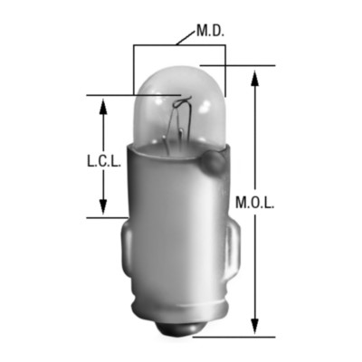
bayonet bulb
In my list of items included in the charging system, I failed to mention one last thing: the charging system failure light (labelled "Ignition"). This seemingly innocuous light bulb does more than just tell you when your charging system is fried. Of course, it does that and it is able to do that because of this other purpose. It provides a light 12v current to the alternator through a means other than the thick battery-direct cable. When that 12v meets another 12v coming from the alternator, no light. When the 12v meets ground, the light illuminates. Cool. This small 12v signal also initializes the magnetic field in the alternator so it can generate electricity. Without this little signal, there is no field, so no power generation, eventual system failure while you're trying to exit OR217. Neat. So, at some point after learning that my charging system was sickly, that little bulb died. Did I need a new battery? Maybe, the old one wasn't too old, but it was a discount brand. Did I need a new alternator? Probably, it was original and had the rust on it to prove it. Besides, 105 amps is far better than the 43 amps you get from the original or direct replacements.

top: blown bulb
bottom: new bulb
So, how do we prove this? Well, first, when you turn the ignition switch to run, you should see that little light. No light? Check the bulb. Assuming you missed that, or just want more proof, start your engine anyway and check the voltage at the battery while running the engine above 2000 rpm. If you're not seeing around 14v, you're not charging. Replacing the bulb is inexpensive ($2.50US per bulb at NAPA), though hard to get to. I was able to access it from under the left side of the dash by running my left hand up along the steering shaft, behind the tachometer. The bulb and harness are pressed into the plastic holder, and held in simply by friction. A slight tug on the harness will free it. The wires are kind of short, so getting the bulb down low enough under the dash so you can see and replace may be the hardest part. Well, that and getting the bulb and harness pressed back into place. Since I was up in there, I checked all of the bulbs, one at a time, to make sure I didn't have to get back up under there again any time soon. Fortunately, there was only the one.

Even if the "Ignition" bulb weren't critical to getting a charge, it is wise to run with all of your warning lights working. Gauges are great, but when you're enjoying the scenery or enduring bumper-to-bumper rubber-banding traffic, you may not note your gauges as often. A bright red light on your dash attracts the eye. And, in my case, I don't have a battery / charging gauge to tell me how well my electrical system is. I like the stock look, so I doubt I'll change that, but if I wasn't thinking about it before, I kind of am now.

Anyway, that's it for today. Thanks, as always, for following along.