Showing posts with label vacuum. Show all posts

Tuesday, October 5, 2021

Resolving the Stammer

In the 2 major trips I took this Summer (2021), my road reports focused mostly Hapy's handling, the wind and the traffic or road conditions. I mentioned, sort of in passing, about the engine stumbling or stammering, having an error code thrown, and the occasional blanket of smoke. Today's post covers how I resolved this condition.

I should call out that the last trip of the season (for Hapy's birthday) did not include a code being thrown. He struggled into the headwind on the way there, but cruised with a tailwind on the way back. In neither direction did he throw a code nor dump smoke, but there were bumbles. So, I did this maintenance so the next trip would not be wanting for power.

P1550
Let's start with the code that was getting thrown: P1550. This indicates: Solenoid Valve for Boost Pressure Control (N75) - Control Deviation. in short, the thing that controls the turbo is not behaving consistently. So, the turbo is dumping boost to protect the engine. The result is a loss in power, sometimes a considerable loss. When I first noted the stumbling engine, I assumed it was fuel related. I replaced the clear fuel filter, because it had some stuff in it, but while that may have helped with consistent fuel delivery, it did not meaningfully address the engine stammering.

As I reflect back on the drives, we should have had WAY more power. I just got bigger nozzles and had the computer chipped. We should have been flying down OR-22, limited solely by the completely soft setting on the adjustable shocks. Instead, I was back to climbing hills in 3rd. It didn't register while we were driving, but it is now. Since we were sporadically getting a P1550 code, the turbo was sometimes dumping boost on the ground.... and creating a nice smoke blanket in the process.

Vacuum Lines First
stock hoses
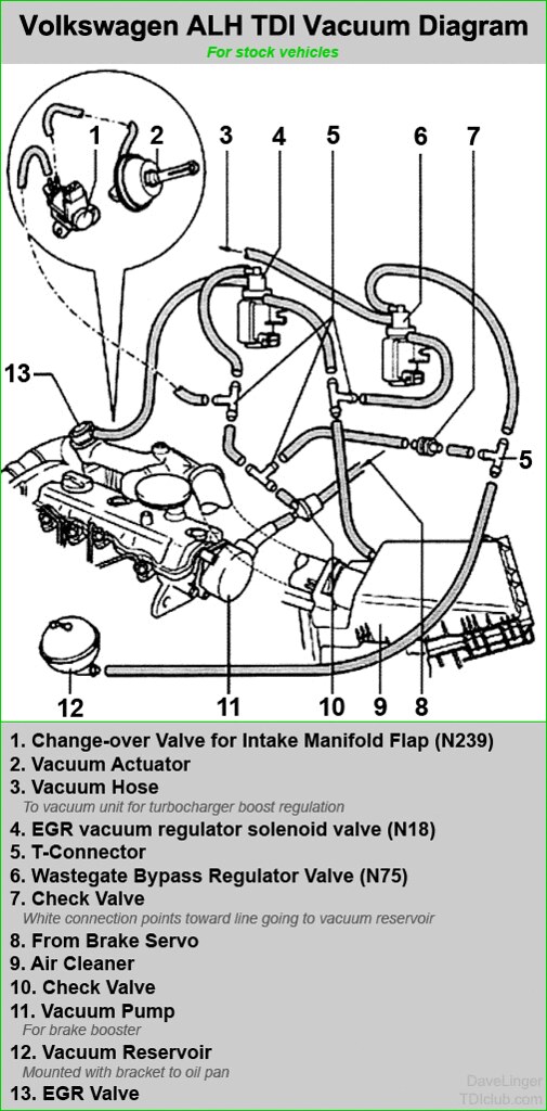
Throwing parts at a problem is one way to solve it. Most people don't like resolving that way, though. When you have vacuum issues, which a P1550 error code usually means, there are some parts you kind of need to throw at it. If you only want to change the one thing that's wrong, you need to check all of the vacuum lines and appliances (turbo wastegate, N75, N18, EGR, ASV, vacuum ball, brake line, etc) and replace the one that is not holding pressure. The least expensive solution is to disconnect and re-connect all of the hoses. Sometimes they work themselves loose, and when you put things back together again, they just work. While cheapest and least guaranteed, this is also the least satisfying path.

If your vacuum lines are over 10 years old, like the ones on Hapy are, then you are due for replacing the lines anyway. Many of Hapy's hoses removed with little effort, almost falling off. Others were brittle and baked on and some others looked like they could have been replaced a couple of years ago. My hoses were following the stock pattern, but the other 2 valves (for Exhaust Gas Recirculation - EGR and Anti-Shudder Valve - ASV) were just blocked off. So, I switched to the simplified version (image below, courtesy of DaveLinger of TDIClub), leaving the unused valves in-place and wired, but without a vacuum source. This should reduce the opportunities for vacuum leaks to appear in the future.

There are kits on the 'net for a couple of meters of 3mm hose and a couple of meters of 5mm hose. The 5mm is for the line from the N75 to the bottom of the turbo and from the N75 to the air cleaner. The rest on Hapy are 3mm, but from looking at the diagram, I would expect that the line from the "T" to the N18 should also be 5mm. All of the lines I removed from Hapy were 3mm: I didn't have any 5mm when I did these 10 years ago. I am sure the VW engineers used the bigger diameter hose for a reason, though, so I installed 5mm hose to/from the N75. Anyway, replace one hose at a time, cutting the old hose off by slicing along the plastic nipple (to avoid breaking it). This will cost, like $30US, in hoses and in about an hour your hoses will be good as new. Possibly better. P1550 possibly fixed.

Brake Booster Line
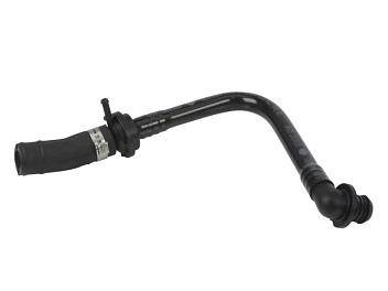
So, you still have a code or lack of power? Next, I would replace that big vacuum line from the vacuum pump to the power brake. These age and crack like the others, but the replacement is not in the hose kits. For another $30US, you can replace this. I was about at this point when I kinda remembered that my brakes were not as responsive, and I had to push harder to get the bus to stop. Sometimes. I had thought it was weight-related and even hit a trucker scale on the way beck from 4Peaks to see if I was especially heavy (4400 pounds, btw). I wasn't. Perhaps I was stopping with only partial vacuum boost or even power boost free. Hoping the power booster on the brake was not the cause, I continued down the path of parts I had on hand. My hose was original, and while there was a little cracking at the vacuum-pump end, it looked pretty good. Still.. you can't tell if a hose is failing by looking at it. Glad I replaced it.

Replace the N75
no EGR, no ASV
Last "inexpensive" thing to look at is the N75. I put quotes around it because it is still $70US. I suppose the vacuum ball or the little grey/white check valve could be the issue and these are fairly inexpensive. If you are still getting the p1550 after all the replacements above and the N75, you may have an issue with the wastegate actuator, or your brake booster. Remember the booster failure on Oliver, the MGB? For reference, here are the links for the finding and the fixing posts. 

Replacing the N75 is usually as easy as replacing the hoses. 3 hoses and a 2-pin plug-on-a-cable connect to it. It is held to the firewall with a couple 10mm bolts. I ordered both the hose kit and the brake booster line as well as a N75 when I attacked this problem. Since my engine is a first-year ALH, the 2-pin plug is different from most others, so the N75 on-market does not direct swap in. The plug needs to be re-wired or the pins pushed out of the old / into the new. I left the N75 in my supply heap and just did the lines. I figured that if I need to cut some wires or play with the pins, I want to be sure that it will actually solve a problem, rather than just create work. I had to remove the air intake to get to the vacuum lines so I cleaned the air filter while it was in-hand.

Test Drive
With the vacuum lines replaced and simplified, I was ready to see if the stammering issue had resolved. Prior to doing this work, I was still driving Hapy around as my "daily" driver (quoted because with the pandemic I don't actually drive everyday. Maybe I should say my "weekly" driver), and I was still getting sporadic stammering issues. So, I figured if I could just drive to my favorite burrito place (Taqueria El Gordo) without a stammer, I'd have solved the problem, and gotten dinner. I say that because it is just far enough away for the stammering to appear. Even if it didn't solve, I would still have a killer burrito. It was on a drive to Gordo's that I could easily re-create the stammer problem within a short trip, so I figured it was a decent test-track.

What's that saying about "the best laid plans"? Well, instead of going to the burrito place, Boo and I drove right past it and out to Cornelius (west of Hillsboro) to see some live music. Hapy suffered no stammering, and he had plenty of power. I didn't really put my foot into it, but he popped off the stop lines well. At no point on the drive there and back did he stammer, nor lay down smoke. I am calling this solved: failing vacuum lines. 

That's it for today. Thanks, as always, for following along-

Tuesday, June 22, 2021

MGB - Brake Booster Replacement

In my last post about Oliver, the 1978 MGB, I mentioned that the brake booster was the cause of a vacuum leak in the engine. This vacuum leak was causing cylinder #1 to run very lean compared to the others. Fortunately, Oliver has not seen much road time, so the engine should be fine. Regardless, today, I cover the fun of removing and then installing a replacement brake booster.

I would like to note that the body work on Zed came to a full stop when the Oregon weather predictably shifted back to cold-wet. For those who don't live here, we experience a wonderful donut-hole of beautiful weather in April/May smack in the middle of the cold-wet. The cold-wet returns for the month of June, usually lasting until Independence Day. So, I entertained myself with other projects, like this, while we waited for the weather to change back. After yesterday's high temps, I suspect the cold-wet is over until October.

Booster in an MGB
We start with where the booster lives in the small engine compartment of the MGB. The brake master cylinder, the clutch master cylinder and the brake booster all live together, attached to one another through the "pedal box": a rectangular steel box just in front of the firewall on the driver side. Closest to the rear is the clutch master cylinder. It is bolted to the back of the box with a lever extending into the box and attaching to the clutch pedal with a pin that is held in with a cotter pin. Attached to the front of the pedal box is the brake booster, with 4 1/2" nuts. This has a lever passing rearward, attaching to the brake pedal with a similar pin-with-a-pin design. To the front of the booster, the master cylinder is attached (2 nuts either 7/16" or 1/2"). Into the master cylinder a rod is passed from the brake booster.

You can imagine the brake action then: pedal is depressed which leverages against the clevis pin to press the lever into the brake booster. The brake booster converts some engine vacuum into more braking force which is then applied through the rod to the master cylinder.

Booster OUT OF an MGB
booster out
The Bentley manual has a step-by-step instruction for removing the brake booster, but I found the instructions to fall down. It started with removing the cover on the pedal box. I agree with that. It then described removing the clips for the brake lines leading to the master cylinder within the engine compartment. I agree with that. Then, it instructed to remove the bolts holding the brake master cylinder to the front of the booster. I also agree with that. At this point, the brake master cylinder can be slid forward off the booster-rod. By doing it this way, no air is introduced into the brake system. I likey.

Then, the instructions said to remove the cotter pin holding the clevis pin for the brake pedal to the leaver on the brake booster. This is not possible for anyone with adult male (and probably female) fingers for width and no one with child fingers for how deep you need to go. The gap between the side of the box and the partition which runs front-to-rear is not wide enough for fingers. I tried long needle nose pliers, but I concluded that even if I got the cotter pin free, and got the clevis pin off, I would not be able to re-install this way. So, I started my own path from here.

My plan was to remove the pedal box with the brake booster still attached and remove the booster from the pedal on my bench. Unlike the brake cotter pin, the partition is much wider on the clutch side, so my average-thickness fingers were able to remove both the cotter and clevis pins without too much difficulty. So, with the pedal disconnected, we remove the clutch master cylinder from the box by removing the 2 bolt/nut combinations that attach it from the rear.  Once removed, the clutch master  cylinder can be pushed rearwards out of the way. Next, we focus on the pedal pox. There are 2 bolts from the top, along the outer edge of the box nearest the centerline of the car. There are 3 bolts from inside the driver footwell going up. Last, there are 2 bolts from behind the dash running forward. Once all 7 bolts are out, the box is only held in place by gravity and the seal. Some light upward pressure on the brake booster and the unit pops free. Getting the unit out of the car took some wrestling, but I think this was more difficult because I could not see where the pedals were dangling. I found that by rotating the unit 90* clockwise helped the pedals to make it through the hole. had I read my old post about removing the pedal box (See MGB - Master Cylinders (Part 1)) or the post about the install afterwards (See MGB - Master Cylinders (Part 3)), I would have known to loosen the bolt fastening the clutch pedal so it dangled a little bit more. This would have made the removal much less of a muscle effort.

pedal box upside down on
workbench with old booster
Once the pedal box was out, it was a simple matter to remove the cotter pin and clevis pin between the brake pedal and the brake booster.... from the underside. I removed the remaining nuts on the brake booster, and started the install by performing the steps in the opposite order: attach the brake booster to the front of the pedal box. Thread the clevis pin through the lever and pedal, minding to include the washer before re-inserting the cotter pin.

Booster Back In MGB
With the unit in the same relative state of assembly as it was in when it was removed, I returned to Oliver to install it. I approached the install in the same manner as it was removed: rotated 90* so the booster was pointing across the engine. The pedals didn't fit, but with some rotating of the box and squeezing the pedals together, I could get them to fall through. Then, I wiggled and rotated the box, checking for cables wires and tubes from getting underneath until it settled in place. I decided that I would do the hardest first, so I did the clutch pedal/master first. I bolted the clutch master cylinder to the rear, after wiggling it around to fit, setting the lever alongside the clutch pedal. Then, I attached the pedal with the clevis pin and cotter pin. I found there was more play that I expected at this joint point, and concluded that I got the clevis pins backwards between the brake and clutch. Food for thought if you are doing this: the longer clevis pin is for the brake.

new booster in
With the clutch master cylinder tied in, I added the brake master cylinder to the front. This is much easier to get to. Once fitted, I started fitting the pedal box to the body. Because of the brake and clutch hard-lines, the pedal box is reluctant to move. I found that putting the 2 bolts through from the dash forward into the rear-most part of the pedal box allowed me to move the box into position. Once the bolt holes along the inside edge (2 of them, one 1/2" one 7/16") aligned, I set those 2 through. Last, I got back on my back inside the driver footwell and sent the last 3 7/16" bolts through the outer edge of the pedal box.

Brake Booster Hose
With the new booster on the pedal box and the pedal box in the car, all that remained was connecting the vacuum hose. I had oriented the booster upside down from the original so the vacuum nipple is on top, rather than below. I did this because of the significant heat source below the booster (exhaust) that is less present above. Also, the hose is much shorter and straighter from intake manifold bung to brake booster nipple. Wanting to avoid any possible issues with the original one-way valve on the intake manifold, I replaced it as well.

Re-Tune and Jetting
Because the old booster was creating a vacuum problem, I re-did the ColorTune tuning steps. Similar to the first time, I tuned using cylinders 1 and 3 but achieved a nice blue in both banks this time. I did swap out the idle jets (50F9 jets), but in order to find blue, I had the idle mixture screws further out than 2 full turns. I will drive Oliver around a little bit, but I think I may need to go up to 55F9 jets if the instructions in the SK Racing manual are to be followed. I noticed that the SK Racing product page describes the "pilot jet" in the carb set-ups they are selling today as 55. Assuming this is the idle fuel size, that's more support for trying 55F9 idle jets.

Since these SK Racing carbs are so similar to the side-draft Weber, here's another tuning link I found specifically for Weber. Notice how that article indicates the starting spot for the idle mixture screw is 2.5 turns out? That is about where mine are now. Curious. One last link, again on the much more plentiful Weber DCOE, but this time about some recommended jet sizes. It recommends the 50F9 idle jets for a late B like I just put in, so honestly, at this point, it will come down to a road test.

under the jet cover plate
Swapping out jets in this carb is seriously one of the easiest things I think I have ever done on a car. There is a cover plate on the top of the carb which is held in place with a slotted bolt. Once the cover is removed, the 4 jets (one idle per side and one main per side) are held in with slotted jet holders. The idle jets are the ones further from the engine / closer to the air filter. The holder threads out, and the jet is held in the holder basically with friction. The old jet slides out, the new jet pops in and you thread everything back together again.

The engine tune did not meaningfully change after the re-jet, so I concluded that the air-fuel mixture from the old jet was virtually the same. So either I removed a pair of 50F9 jets only to put in new ones or the old ones were a similar enough combination that they provided the same air-fuel at idle. At least I know what they are now.

All that is left is a drive... but wait! I didn't hook up the brake light switch. Well, I did, and after a few days of head-scratching trying to get the lights to illuminate, I realized that I had plugged it in wrong. The source 12V arrives in a dual plug, and the signal to the brakes departs through a single plug. I had thought the single plug was from the old carb-preheater, so I had failed to send either side of the switch to the brakes. Instead, I simply wired both sides of the switch to the 12V supply. Hahaha. Simple fix. Once the cars were shuffled so Oliver could get out past the herd, I did a longer test-loop. It did not take long to get the engine to normal operating temperature and he ran great. There was a slight stumble (bog) from dead stop, indicating that he was still a little lean. So, once back in the garage, I turned the idle screws about 1/8 a turn more rich. When I rev'd him from idle, I could not note a bog so I figure he is fairly close to tuned now. More road testing will confirm, and I expect I will fiddle with these screws as weather and altitude factor.

Thanks, as always, for following along-

Tuesday, June 8, 2021

MGB - Finding Vacuum Leak

Following my last post about Oliver (the 1978 MGB) when I got his timing square, I knew I needed to get his carb tuned. Today's post covers those efforts. This continued in parallel with the body work on Zed (until the weather turned, when Zed work stopped). These spring days, when the sun doesn't go down until 9PM creates LOTS of play-on-cars time. Love it.

A-typical Carb
We start with the most basic learning: what kind of carb is this? When I bought this car, the prior owner had been executing some improvements. For the most part, I can't complain about any of them... except the hack-job on the exhaust. Honestly, he could have been just making do until he had the cabbage to do what I did. Anyway, one of the improvements was to eliminate the stock dual Skinner Union (SU) carbs and swap in a side-draft carb. This isn't your standard Weber DCOE, though. Instead, the prior owner went with a SK Racing carb. The SK Racing (now known as OER Racing) side draft carb was (according to Dog283) one of the best engineered side draft carbs built, just as carburetors were falling out of favor for the new computer-assisted fuel injection systems. Dog283 continued "(the SKRacing side draft) combine(s) the best of the the Mikuni Solex PHH, the Weber DCOE and the Dellorto DHLA". That's a fairly strong statement. Unfortunately, the implementation on Oliver had fallen out of tune, so our MGB was not getting the lofty results this statement describes.

We start with looking for, and ultimately finding, a shop manual for the SK Racing side draft carb. If you have one of these carbs and need a copy of this manual, I'll happily share it. Near the back of it are the set-up steps detailed in the image of the page on the right. Basically, set the idle speed screw so it is just barely touching the tang, thread the idle adjustment screws all the way in until they just barely seat and then rotate them back out 1 full turn. Start the engine and get it to normal operating temperature. Then, tune the adjustment screws first until the engine runs smoothly, then set the idle speed. I did that, but I still got sporadic backfires when I rev'd the engine. I was starting to think that all that ignition work was for nothing.

Exhaust Leak Checks
Before I started investing time in the carb, I figured it would be a good idea to see if there were any leaks in my exhaust which could account for the backfiring. There were. To test, I started by cleaning out my shop-vac (washed out with a hose) and grabbing a squirt bottle of soapy water. I thrust the exhaust end of my now-clean shop-vac up the tail pipe and turned it on. This created backpressure through the exhaust. The tail pipe was not completely blocked so lots of air rushed right back out, but there was enough pressure to execute my test. I started up front, in the engine compartment and shot soapy water on the mate-point between the header and the head. No bubbles. I then got under the car and hit every joint, and found some bubbles. I concluded that I created leaks when I added in the catalytic converter. I turned off the shop-vac, loosened the joints, slid the pipes apart and applied some copper exhaust gasket maker and then re-connected the pipes. I nutted them back down and re-checked with the shop-vac. Things looked fixed (no bubbles at all but one joint where there were very very few), so I moved on to tuning, expecting my backfire issues had been identified and resolved.

Gunson ColorTune
Back when I was doing the other work on Oliver, I kind of expected difficulty with getting the carb to adjust. So, before I finished getting the ignition installed, I ordered a Gunson ColorTune. These things are pretty neat, but not terribly useful, I suspect, for the computer-controlled fuel injected systems. The kit includes a looking-glass spark plug, a lead, a tube with a mirror and a brush. I only needed the glass spark plug and the lead. The looking-glass has a solid-center where the spark is produced, with a ring of glass around it. The glass ring is then encircled with threaded metal so it can be threaded into an engine. The tube with a mirror is for spark plug holes that are hard to see. To use the kit, you remove one spark plug and thread the looking-glass plug in it's place. You connect the spark plug lead to the end of the lead from the kit, which is threaded onto the glass plug. Then, you start the engine and look at the color of the combustion in the chamber through the glass. If the color is orange or red, your mixture is too rich. You want the color to be "Bunson blue" = the color of a Bunson burner, from, like science class. The images on the right, here, help lead you to a good tuning. Notice that light blue or white-ish is not on here. If you are in the white-zone (Airplane, the movie reference here), your tune is too lean.

I was unable to get cylinders 1 and 2 anything better than a very light blue even after adjusting the idle mixture out past 1-1/2 turns. Cylinders 3/4 did not do much better. Based on the manual, I believe the idle jets may be too small, so I ordered a pair of 50F9 jets ($7US each). If I am correct, the current idle jets are 45's and this change will allow idle-mixture within 1-1/2 turns of fully seated to sit in the Bunson-blue color.

Still, I kept going, wanting to get the tune as good as I could. While looking through the glass I increased the fuel mixture incrementally, but the misses and backfires persisted. I could see the backfiring through the glass in cylinder 1, and concluded there had to be a leak somewhere. I also figured that backfires within a cylinder that has a glass plug was probably not a good idea. I had already looked on the exhaust side for leaks, so that left the intake.

Intake Vacuum Leak Checks
There are not many places where a leak could appear in the intake: the mating point at the head, the mating point with the carb, the carb itself and the brake booster. With the engine running, I carefully sprayed some WD-40 onto the various mate points. If there had been a vacuum leak, the vapor would have been drawn into the engine and the RPM would have bumped in response. Spraying something flammable onto a hot engine is dangerous. I strongly urge you to keep a fire extinguisher handy if you do this. In my case, the engine did not change and nothing caught fire.

So, I shut everything off and considered the brake booster. I removed the hose from the check valve, which is threaded into the intake manifold heading to cylinders 1 and 2. I checked the vacuum of the brake booster through that hose with the MityVac. It would not hold vacuum. I removed the check valve and cleaned the valve and the intake manifold where they met. Then, I put some copper gasket maker on the threads of the check valve and threaded it back in. I figured if that was the leak, I just solved it. I jabbed the hose back onto the check valve and hose-clamped it tight. Then, I eliminated the brake booster by threading a bolt into the end of the hose which had previously been attached to the booster, and started the engine. Oliver ran great! I could rev him up and down without any backfires demonstrating that the brake booster was my vacuum leak.
check valve in foreground,
intake in background

I wanted to prove it for sure, so I hooked the booster hose back up to the brake booster and started the engine again. I rev'd the engine up and down... the back fired returned. I pinched the vacuum hose with a pair of pliers and I could hear the engine RPM's settle. Neat. Rev rev rev... no back fires. Remove the pliers, RPM increases... rev, rev, rev... backfires.

Fortunately, these brake boosters are being manufactured now. I didn't realize these were not available until recently, so as much as I would like to self-blame for not replacing the booster when I replaced the brake and clutch master cylinders, it wasn't available then and they are fairly expensive now (~$200US). As of today, they are not available through Moss yet. I had to go through another vendor (EnglishParts.com, they're lovely). I concluded that any carb tuning I had done would need to be redone once the brake booster swap was completed. 

That's it for today. I will install and post about the brake booster when it arrives from the MidWest. Thanks, as always, for following along-

Tuesday, December 17, 2019

Nemo Rides Again

Returning to the Nemo work, today we button everything back up and test things. In the first of these 3 posts (See Sadist Engineering), we diagnosed and removed the head. In the second (See Nemo Head Install), we took the head to a shop, had it tested and decked and then installed it back onto the engine. So, we start with the head and engine back together again, and torqued down.

Intake and Turbo
With the head on, next came connecting the turbo: slip a new gasket between, then slide the other 2 bolts through. I held the turbo from below and got those 2 bolts to thread in by hand. Once I was able to get them tightening down with a spanner, I could get the bolt closest to the head through to the turbo and finger-thread in. Tighten to spec. The intake was a bear to remove, but it was actually kind of easy to install (with a new gasket). I did not need to replace that one bolt, either. In fact, upon inspection, I couldn't easily distinguish it from the others. I was able to get them all snugged down tight. Torque spec was lower than I expected (like 20 pounds or something), so these were on too tight when I removed them.

Timing Belt
The last big/hard piece was the timing belt. Luke had really cleaned the head, so there weren't any paint-markings on the gear on the cam sprocket when I got it back. So, getting the belt in the exact same spot threatened to not be the simple case I had expected. I did know, though, that the engine hadn't moved and the head was at TDC, so I just needed to get the belt perfect-tight on the left side (front-is-front) and make sure I did not shift the engine timing when the belt was tightened. It turned out that I was smarter than I thought, and had put the head cam mark on the belt where the timing dimple appears on the gear. So, the alignment was actually a snap. That's one to grow on: mark the belt based on the timing mark and the shop can't erase them on you. I was able to re-use the belt tensioner (belt was replaced less than 20K ago) by slowly re-compressing it in a vice and sliding a paperclip into the hole to hold it compressed during install. Put on the tensioner roller, put on the tensioner verify everything is right and pull the pin. There are much better instructions with the belt kit than I could provide in this space. Regardless, once the belt is on, it is recommended to rotate the engine one full rotation by the crank and then verify that the timing marks are still spot-on. I apologize for not taking any pictures along the way, here. I got going and kinda forgot to.

Accessory Belts
After the timing belt is on, the lower timing belt cover is added and then the lower crank pulley. At this point, I put on the accessory belts, and the belt tensioner for the longer serpentine belt.

Hoses
With the timing belt and corresponding covers on, the hoses were next. Since I did not swap any hoses, and I removed as few ends as I possibly could, the hoses flopped back to where they were, and it was rather simple to plug hoses onto nipples. Getting the evil outlet flange on, though, was it's typical challenge. I used 10mm bolts instead of the Allen-keyed bolts and found them much easier to start and torque. I consider this an upgrade. Before I switched from cooling stuff, I mounted the overflow bottle.

Vacuum
Once everything else was in place, the vacuum lines just flopped into place. I didn't expect that, but I had only disconnected a few of them. I needed to find one that simply disappeared: the line from the intake manifold to the fuel pressure release. This is only about 4 inches long, and I had thought that maybe it wasn't on there when I started tearing things down. Turned out, I simply dropped it and found it on the tarmac after we moved the car. By then, I had put on a fresh hose.

Electrical
Re-installing the spark plugs was next for me. I could have done this earlier, but I got to it now, when I needed something that didn't require me to be bent over because my back was starting to flare up. So, I gap'd the plugs (.028) and installed them. Then, I plugged in the coil packs, bolted down the related grounds and verified everything I could reach was plugged in. I noted a few that could only be solved once the front end was re-attached, but that was becoming a very short list.

Front End Assembly
test ready
And just like that, I was ready to put the front cowl / radiator support back on. This would have been much easier with a helper, but I started with the passenger side, getting one of the upper bolts by the fender loosely threaded in. Then, I repeated the driver side. Now, I could arrange the large steel bar which runs behind / below the radiator and the lower mounting points of the cowl. Held in place with my knee, I set first the passenger side, then the driver side bumper supports with a single bolt. Bouncing from one side to the other, I threaded in the other bolts, and then tightened them down.

With the front end mounted, I could complete the hose connections to the radiator and confirm the route of the charged air. I swung the A/C condenser around and mounted it to the radiator and then added the large front inter-cooler. I plumbed the large pipes for the inter-cooler, and then checked for missing connections and not-plugged-in things. I plugged in the horns. I mounted the headlights and plugged them in. I found and plugged in a small green plug below the radiator and the sensor just above the lower radiator outlet. Or is it an inlet?

Test
I had run out of time and daylight to do anything else, but I knew the next step was to fill the system with water and test fire it. I wanted full daylight for that, and a night to sleep on it so I could come back and inspect with fresh eyes. The next morning, it passed visual tests and T dropped by for the test start. I filled the system with plain water.. yes, I know that's not a good thing to do long-term. This was simply to see if it started. I figured if it didn't I would be draining the system to fix it and didn't want to waste good coolant for that. We hooked up the battery and turned the key. Vroom-vroom.

We let the car sit and idle while the temperature came up. There were no drips so I ran my gloved fingers around the various coolant components. The gloves came back without moisture, so we took it for a spin. We drove for 15 or 20 minutes and watched the engine temperature rise and fall as we pushed it and let off. When we returned, we backed Nemo back into the service parking spot and let it idle again. No drips, no coolant loss. And, the temperature sat still.

Road Ready
We turned off the engine and did our little happy dance. The next day, I drained the coolant system and filled it 50/50 with G40 coolant and water. Once the system was burped of air bubbles, it was ready for T to take back home.

So, that's pretty much it for Nemo. I replaced a couple of fuses for the tail-lights, and the registration has expired, but otherwise, the car is ready. T collected the car, drove home to Eugene without incident and has driven it on errands and fun-runs multiple times since. We'll call that a win. Thanks, as always, for following along-
Tuesday, November 26, 2019

TDI install retrospective: Vacuum System

Continuing the process of back-documenting what I did to put a TDI engine into an old (1972) air-cooled VW bus. Today's post is all about the vacuum system. It is super short, because there really wasn't much to it. Before I start, Hapy ThanksGiving and White Friday to my US readers.

Bus Needs
The TDI has a few things that require vacuum, and the bus has one: the brake booster. The original engine supplied vacuum from the manifold through a pipe that runs along the driver side to the brake booster underneath and behind the driver seat (under the bus). Fortunately, 30 years of engineering marvels later, the brake booster in the modern car is supported by a very similar vacuum. It is so similar, in fact, I just needed to plumb the brake booster outlet on the vacuum pump to that pipe and that need was solved. Power brakes? Check.

TDI Needs
from TDIClub
The TDI engine has it's own needs. The turbo needs a signal to dump boost. That actuator is vacuum powered. The EGR is vacuum signaled as well. Each of these have a different valve triggered by a signal from the computer (the N75 and N18 respectively). Since I pulled my EGR equipment, I simply blocked the signal line leaving the N18 and left everything else in tact. I mounted the control valves to the floor support that runs just to the inside of the spare tire well. The system needs the vacuum ball, the pump, of course, a bunch of T fittings and a source of clean air. I source the clean air from the main air intake. I will get to the air system later, but simply put, I took an old air-flow metering (MAF) housing and replaced the sensor with a simple vacuum nipple. This air flow metering housing was the same size as the rest of the fresh air intake, so it was just one of the components that were strung together after the air filter.

I spent a great deal of time drawing and diagramming before I did this. Ultimately, that was unnecessary; I was working from fear. So many systems work the other way: air pressure, water pressure.. the direction of the media is the same as the force, so when you look at a vacuum diagram, its all upside down. Air goes one way, the force of the air used to open and close things goes the opposite direction. Basic vacuum versus pressure, like the switch on your MityVac. It is the media (air) leaving that is the force, not it arriving.

With that perspective, I could made a plan. Ultimately, all I was doing was changing the lengths of the hoses, so this turned out to be pretty easy. I set the pieces out and started replacing lines with new vacuum hose. In many cases, I cut a different length than what was originally in-place because my placement required it. I retained all pieces of the system with the sole exception of the EGR (which I may re-introduce). The hose that would have gone to the EGR was simply terminated with a cap.

Prior related posts:
Preparation
Fuel System
Physical Mounting

Next related posts:
Air, Intercooler and Exhaust
Primary Electrical
Cooling
Secondary Electrical
ECU, dashpod and Sensors

Sunday, March 10, 2013

Couldn't Stand the Weather

Car stuff today.  Brief?  Is it ever?.  Complains about no garage?  No, actually.  I have to remind myself that owning cars that are over 10 years old with more than 150k miles on them requires owner responsibility.  In that spirit, no complaints; just doing.

Silence Canyon at the pull-out.
Note the snow line in the trees
Cold Shot
While I was getting Flash back from Johnny, he pointed out that the he (Flash) still didn't want to start first thing in the morning.  I thought it had something to do with the vacuum lines.  So, I spent the beautiful Saturday afternoon re-running the vacuum lines.  Some folks may not see that as a perfect Saturday, but it was in the low 60's (F), sunny and the birds were out.  I have evidence of that last part on the side of Flash, but I digress.  Some of the vacuum lines were original.  Yikes.  Most seemed okay, but I replaced them anyway.  I needed about 8 feet of 3mm and 7 feet of 5mm line to do the job.  I have a few extra feet of the 3mm after over-buying.  Anyway, the cold-start trouble persists, so I'll be hitting the interweb (read:TDIClub) for clues.  No codes, no smoke (except on that cold start) and Flash runs fantastically otherwise.

Couldn't Stand the Weather
Sunday (today) was a day for the bus, and a change in the weather.  I mean that both ways.  The clouds rolled back in, dropping spittle-rain this morning.  After running T over to a youth group meeting in Flash, I decided I'd give the bus a go for the pick-up trip.  Remember, that I hadn't taken a test drive to verify whether I'd actually fixed the leak, but I felt pretty confident that I'd nailed it.  He started on the first try.  No real hesitations, but he was chilly.  The drive over was an exercise in getting the gears all slippery.  Shifting was stiff and he wanted to pop out of second.  I sat with the engine running in the parking lot while waiting for T to appear.  He was out of sight, but apparently heard the rumbly rumbly and tore around the corner, beaming.  e knew exactly what I was driving.  As we pulled out of the parking lot, he asked, "how's he driving?".  I responded with driving the bus like I stole him (well, as much as you can with a microbus).  "Zippy," T said.  At this point, the engine temp finally got high enough to trigger the thermostat and allow coolant to really move through the flange and into the radiator.  The temp climbed to 196* and crawled back down.  It see-sawed from 188* to 194* from then on during the drive home.  We stopped to look at the house we had tried to short-sale purchase last Summer.  We saw a puddle forming under the bus and knew then that the "fix" wasn't.  Back to the condo we went, a little dejected after such a promising start.

germane to nothing, it's a Nutria 
When the House is a-Rockin' Don't Bother Knockin'
As we pulled into the parking lot of the condo complex, I noticed the neighbor walking towards our parking spot.  Now, this neighbor isn't one of the condo folks.  He lives in a house that shares the property line.  In front of his house are parked many cars (some volksies).  They split and sell firewood.  They build and sell picnic tables.  There are always one or two folks out front, and a radio is always playing alternative radio.  Modern hippies?  Maybe.  Anyway, one of the guys who live there walked over and asked if we (T & I) could solve a debate.  Apparently, they heard me drive off, and that sparked a whole debate about whether it had a diesel in it or if it was just tuned crazy.  Big smile.  I pushed back the matress and the engine hatch I cut and watched is eyes bug-out.  LOL.  Made my day. Apparently, he and a bunch of folks he knows are mechanics and they specialize on VW's.... mostly the older ones, but they work at a shop I know if (omitted to protect everybody).  I encouraged any one of them to stop on by if they wanna see the crazy TDI-powered microbus.  I added, "if they wanna elp figure out the coolant leak, I live right there (pointing)".  :-D  I'm no dummy, and I'm tired of trying to isolate the leak.

That's it for today.  I'll revisit the leak next weekend.  Hopefully, I'll have a few extra pairs of hands around, even if they're just there to talk and point and drink beers.  To avoid the questions, I spotted that Nutria in the picture on my way into work as I passed a water hazard / green space.  If you've never seen one before, it was big, like a 16" long body plus a nearly 10" tail, nibbling on the grass.  Sometimes Mother Nature is just plain weird.


Sunday, February 24, 2013

What Ever Happened to the Courtesy Wave?

I'll be brief today.  I've been working some crazy hours, and I haven't had my usual sled for almost three weeks, so its been a bit of an awful February.  Here we go...

Flash Returns
So, I got my car back from the mechanic that my wife usually uses.  Her family goes to him, and with Justin unavailable, I thought I'd try him.  In my last post, I lamented all the stuff I had to pay for, but he gave me a fair deal.  Unfortunately, when I got the car back, the turbo doesn't turn on anymore.  I think its a simple case of a vacuum line failing or the N75 going bad.  It just seemed peculiar to me that the turbo was working fine when Flash went into the shop, but now (many dollars later), I still have to do something on it.  Grr...

Traffic Patterns
Over the years, I've driven lots of miles.  From following the Dead around parts of the country, to delivering pizzas to basic commuting, I've driven many miles.  I'll make jokes about how I learned to drive in NY, and that meant you only needed 2 fingers: a middle one to communicate visually and one for the horn.  There's a spark of truth in that, though.  There is a whole means of communicating through your horn that many drivers don't understand.  There's the "hey buddy" short toot, the "wake up" long blast and the repeated medium-length "you're an idiot" honks.  All I hear anymore are the one-shot medium length "I'm pissed because I think you invaded my personal space" honks.  Boo.  Learn more.

Hand Waving
Take away the middle-finger-for-communicating joke, and there are many ways to communicate with just hand gestures.  We "palms up" to show no-harm-meant and wave someone in front of us with varied degrees of condescension: the holier-than-thou single waft over the wheel, the frantic I'm-in-a-big-hurry waving, even a frowny faced one-wave come-hither.  They all effectively say the same thing: I'm letting you in, but I really don't have to.  What has all but disappeared, though, is the response once they have gotten in front: the in-front-of-the-cabin-rear-view-mirror big-arm wave of thanks.  This is perhaps the biggest indication of traffic politeness decay.  When traffic merges, and you slide into a spot that barely fits, you big-arm wave.  Most drivers will give you about 2 seconds to do so before they retort with tailgating, headlight flashes or the poorly-spoken "you're an idiot" medium length honk.  Please make the extra effort and help calm everybody down.  Its not a race...

That's about it for today.  I think I found the true source of the leak on the bus a couple of weeks ago.  I'll post on that individually later.  Thanks for following along...

Tuesday, October 12, 2010

Won't Get Fueled Again

In my last post, I said I finally figured out what was going on with my fuel system. I'll explain that today, though I won't have pictures of the fix as I'm still waiting for a part. Also, the vacuum system is finally finished, marking one more completed subsystem. Queue the Who: "Yeah!"

Fuel Me Once, Shame On, Shame On Me
So, I tested and re-tested trying to get fuel to travel through the lines up to the injection pump. I determined that if I put a one-way valve into the vent / return line from the filter to the tank, fuel would travel up the feed line. This was true, so I put a valve in, and I was able to get the engine to run once I primed the lines. The problem is, once the engine shuts off, and the operation sits for a while, the Injection Pump loses its prime. Huh? Wha' Happen'd?

Fuel Me Twice, Um... Uh... Won't Get Fueled Again
The fuel slowly trickles back into the tank via the feed line. I hit TDIClub, and found that the stock TDI placement has a one-way valve at the tank to prevent a loss of prime. Dumbly, I took the one-way valve from the return line and put it into the feed line. Well, this didn't work, since the return line was now plling air again. Grr... ordered another one-way valve. It'll arrive i na couple of days, and I'll slap it into place and re-prime the lines.

Fresh Air, Sucka
The last bit I completed was getting the vacuum system all sealed up. I had a posting a while back that traced the vacuum system. At that time, I didn't have the turbo line in, nor the filtered air tap. I completed the turbo line when I got the intake work done a couple of months ago, but it wasn't until this past weekend that I got the filtered air tap done. In the bits and pieces that make up my filter -to- intake, I have an AMSOIL air filter connected to a MAF body. This MAF body is connected to a short flexi-hose which connects to a second MAF body. This second body has the actual sensor in it. This real MAF is connected to a rubber 135* switchback sleeve which connects to the stock intake. The first MAF body has a diamond-shaped blockoff plate on it, and it is into this block-off plate that the vacuum nipple was inserted. The vacuum line fit easily, and is routed behind the filter -to- intake chain I just described. I don't have a good picture of this (it is under the rear cabinet), but it fits well, even with the wiring mess in that corner of the engine compartment.

I'll touch on my efforts with the heat later on. Thanks for following along-

Sunday, August 29, 2010

... and we're back

I may have mentioned in my last post that I was going to be traveling for a bit, so I wouldn't be getting much done on the bus. We've returned from our 10-day visit to Milwaukee, Wisconsin with many memories, experiences and additional pounds around the middle. I'll touch on different aspects of our trip over the next few posts while I get back to work, and back to getting the bus running. This time, I'll focus on frozen custard while my taste comparisons are still fresh.

Frozen Custard
When I think of Milwaukee, the first thing I think of (after the smiling, loving faces of my wife's family) is the frozen custard. Folks in the Pacific North West don't have access to this special cold treat, and I have had a hard time explaining it. The closest I've come is this: think of the step from sherbet to ice cream, now take that same step in depth and creamy-ness and you're in custard. Very rich, very creamy, very yummy.
There are many different variants of frozen custard, and it seems to differ regionally. For example, Illinois custard isn't quite as rich, and is more "ice cream -like", according to a custard vendor I've had the opportunity to talk to Even within the city of Milwaukee, though, there are definite differences. We tried 4 different vendors, but did not coordinate a taste-off of all of them in the same place at the same time. The next time we go, though, we definitely will. Maybe there will be a few additional contestants too. :)

Kopps
Kopps is the hands-down best frozen custard experience. They have 2 daily flavors (like mint chip or strawberry), and the usual vanilla and chocolate. I take my taste comparisons seriously, so I'll only rate them based on the chocolate/vanilla. Kopps chocolate is the creamiest and richest, and flat-out tastiest. Their vanilla is good, but not as good as Leon's vanilla. They have a nice water feature around which you and other patrons can sit to enjoy a giant burger, fries, onion rings or just a custard. 4 stars.

Leon's
Leon's takes a close second to Kopps for their custard, but 3rd in ambiance behind Gillie's. Leon's vanilla is probably the best of the bunch, but their chocolate was over-chocolated. It almost had a Nestle-Quik thing happening to it. Maybe the kids like that better, but I like a nice balance. Leon's is the location that was the basis for "Big Al's" on the TV show Happy Days, so it deserves a nod for that. There is no seating, and the parking runs almost right into the order windows, making safety a question for the patrons (especially children who run all over the place once the word "custard" is uttered). I didn't try their sandwiches, but T had a sloppy-joe from them and liked it. "not as good as Kopps," he says.

Gillie's
Gillies chocolate was better than Leon's, but not quite as good as Kopps. Their vanilla was better than Kopps, but not quite as good as Leon's, so they fall into third. They have seating and a nice parking situation, though. I didn't try the food from the grille, and we didn't have their custard fresh - we picked it up on our way home, popped it into the freezer and ate it the next day. It held up well, but I think it may have affected our enjoyment. Custard is always best fresh :) Gillie's is the "original" custard stand Milwaukee, and their patronage has definitely held up. We were there around 9:30 on a Thursday evening, and they were hoppin'.

Culver's
Culver's was definitely the worst. It was not much better than Dairy Queen, so it really wasn't custard. The food was mediocre and the service was lack-luster. We visited the Culver's in the Delles, so the service should have been extrodinary (the Delles being a major tourism spot in central Wisconsin). Still, we left disappointed.

We visited those 4 stores at least once during our 10 days in Wisconsin. Of them, we repeatedly visited Kopps, trying their daily flavors as well as burgers, onion rings, fries, malted shakes, etc. We really couldn't say enough good things about Kopps. The service is great, the choices favorable and the outdoor dining area the best of the 4.

That's all for this one. I wrote this on the plane home, so I haven't been able to work on the bus yet. I plan to get the wiring to the starter first and then R&R the starter. I figure if I can get the starter to spin from the driver's seat, then the R&R should be easy. Doing it the other way seems harder to test. I'll be spending my Sunday worknig on this stuff, and may have new info by the time this is posted.
More next time -

--Added--
The starter wiring has been resolved, and the starter has been removed and re-installed. I have the air intake and filter installed, so all that remains on that bit is the vacuum nipple (which I need to get from the store). I will be attempting my first engine start after I post this. The next post will include pictures / explanation of the air filter, and more detail on what I did this morning.

Wednesday, August 11, 2010

Code Free

My friend (and TDI Mechanical Guru) Justin visited last night, and we made some progress on the VAG-COM codes. We had a minor discovery with the accelerator pedal controller as well, but overall, it was a very positive few hours. That "red ball" project has moved on, and work has settled a bit. We'll see how long that lasts....

Code Free
Justin arrived before I got home from work, ready to get the bus running. He confirmed that seeing the mileage on the dashpod was a significant step, and was able to get his VAG-COM reading application on his laptop to communicate with the engine computer. He brought a 99.5 Jetta harness with him - the complete harness for the entire car. We picked through the harness and noted a single 2-plug connector that hooked the smaller engine harness with the other engine-ish harness. Connecting this did not relieve any codes, but it reminded us of the research I mentioned in the last post about all of the codes appearing on elements contained within that same harness. We took his 99.5 harness and hooked it into my engine, leaving the glow-plugs disconnected, to test this theory. VAG-COM was unable to find any error codes / faults. For the time being, I'll be leaving the 99.5 harness in-place and removing my 98 harness. I'll find the bad connectivity wire and fix it off-line. Meanwhile, this resolution brought us to the edge of being able to start the engine.

Clutch Pedal switch
For some reason that I really don't understand, VW included a switch on the clutch pedal to prevent anyone from being able to start their car with the clutch out. I suppose there were complaints about this, or maybe this is one of those Ralph Nader safety things, but I think its pretty stupid. Accidentally trying to start it in gear has its own notification system: that uncomfortable lurch followed by not starting. Anyway, this switch needs to be depressed to allow the starter to get the signal to start. In the early TDI (ALH model), the switch runs through the comfort system, which I tore out. The only signal that matters, though, is a single signal from that system to the #3 relay (number 185 printed on the top) which is the starter lockout relay. That relay takes start-switched power (50b) and routes it to the starter solenoid when 12V are applied to the relay switch from the comfort system wire. Since the send-side of the relay only has 12V when the ignition is turned to "start", the relay, the comfort system, and the clutch pedal switch are not needed... in my application. We jumpered across the relay, and got around the clutch switch problem.

Still NOT Starter-ing
After we got around the clutch pedal switch, the starter still wouldn't turn. To rule out a bad starter, we sent a test wire directly from the solenoid to the battery and proved that the motor turned. Unfortunately, we discovered that the spacer that I introduced between the adapter and the starter caused the teeth on the starter to fail to reach the flywheel. I will be removing the starter, removing the spacer and re-installing the starter. Figure 30 minutes, but unfortunate that it stood in the way. Also, this indicated that the wire running from the relay to the starter solenoid had a break in it. I will need to cut up the wiring zip-ties and find the continuity break. Since there are 2 splices, it shouldn't take long to find which splice failed.

Throttled
Our last discovery was that the direct connection of the bus accelerator pedal to the throttle switch was pre-loading the throttle signal. This means that even without a foot on the pedal, the computer thought we were trying to be at about 35% (not 0%). This is because the old pedal needs some kind of pull from the old carburetor to keep the pedal upright. I will add some space between the throttle switch and the pedal and add a return spring to provide that pressure. That shouldn't take me very long, once I find a return spring.

That's it for today. There was a lot of progress, and the outlook is very bright. I won't be able to put much time in over the next few weeks for travel reasons, but I know what I have in front of me. First, fix the starter signal, R&R the starter and prove the starter can turn the motor. Then, fix the accelerator pedal bit. Once I have that, I'll re-focus on the air cleaner (AMSOIL) and air-source for the vacuum and then look for the break in the engine harness so I can give Justin's back to him. As always, thanks for following along and enjoy the rest of your summer-

TDI-FEST: Portland, OR Labor Day Weekend

Sunday, February 28, 2010

Hal returns

I'd thought I was going to get a bunch done this weekend, but it just didn't work out that way. Friday was mostly lost to work and messing around with my welder. Saturday was lost to pulling ivy, and the sore muscles that follows.

Today, the weather was beautiful, and I only had a few commitments. Between running kids around, taking the dog to the park and going to a lacrosse parents meeting (and watching the Olympic hockey gold medal game on tv), my day was quickly consumed, though. My wife returned from her weekend at the Oregon Coast with a late birthday present for me: one of them big red tool chest things. So, of course, I spent a bunch of time messing around with that. It's an oldie that was made in America (by Kennedy), and with a little graphite on the slides, it works very nicely again. As you can see by the over whelming clutter behind it in this picture, I needed this very badly. We hope this is the beginning of a much better organized sub-single car garage where we keep just about everything that is used outside.

Turbo to inter-cooler
Between errands, I put together the solution for getting the charged air from the turbo to the inter-cooler. Using the hose that came with the engine, I simply cut it in half and connected it with a 2" stretch of 1-1/4" pipe. At the inter-cooler end, I'm using a copper step-up.

Enter Hal
After getting some tools stowed, Hal arrived. This was the first time I've seen Hal since before Christmas, so we had quite a bit of catching up to do. We ran through the progress I'd made, and he generally agreed with my decisions. It was nice to have another set of eyes look it over. We decided to punt on the dog-bone mount until we get the engine running, and we'll determine if its needed then. Also, he won't be doing the exhaust work. If we find a better muffler, then, great. Regardless, the routing of the exhaust will be done by an exhaust guy. We set the order of work for the next couple of weeks:

cooling system
1- get the 90* bends at the radiator
2- integrate bleeder in the "lower" hose
3- fabricate bracket for the overflow bottle, install bottle
4- finish running hoses

Intake
1- complete inter-cooler to intake charged air line
2- find and incorporate an air cleaner

Vacuum
1- run vac line to the turbo waste gate
2- run vac line to new air cleaner

Electrical
1- plug in everything I can in the engine compartment
2- accelerator pedal install
3- next.... detail the rest of the electrical work needed, and revisit this list.

That should get me through the next couple of weeks. If I can get that much done, I'll just have the electrical system to do. That list isn't that imposing, so I'm optimistic. Hal will be involved for the accelerator pedal install. More next time....

pictures:
top - new tool storage birthday present (yeay!)
middle - turbo to inter-cooler charge air line
bottom - charge air line installed

Monday, September 28, 2009

Roll ready

No, not ready to roll in the 'under its own power' sense. But, Hapy is now set up enough for me to roll him off of the main driveway (where the rainwater pools) up a slight incline to a cement pad next to the garage. Sure, from the outside this sounds like a "shrug" of a post, but it is significant:

I won't lose the Winter.

Pushing Water Uphill
If you aren't familiar with Northwestern Winters, then you really haven't experienced incessant rain. I've lived in other parts of the country and when they see steady rain, it lasts for a couple/few days and everyone starts getting antcy. Here in the Great Pacific NorthWest, 2 or 3 days of steady rain could happen during the Summer drought. Steady rain here is up to 30 straight days of measurable precipitation. So, getting the bus where it won't sit where the water collects is a big deal. Next to the garage will be well drained, on the lee side of the prevailing rain direction, under a tent thing, closer to the tools, light and power in the garage, and last: a portable heater will actually warm the work-space.

Progress
I got a lot done on Sunday, and Hal nearly finished out the rear mount. Starting with his work, he was able to get the rear mount adjusted into place, and the final set of bolt holes set. The rear support bar was then removed for paint. We decided that the tower (hollow box) could be further supported / cross-membered by welding a plate onto the rear (FIF) of the tower. As I consider how that will look, I'll have to think up something interesting to paint there. Maybe a smiling sun or something non-commercially iconic. Hal also got the fuel filter bracket mounted to the right side of the engine compartment using a little bracket extension he fab'ed. We talked about integrating the fuel return line, but we didn't hit on a solution.

On my side, I did the little things under the bus to get it ready to move. This included getting the shift linkage and CV joints (axles) re-connected to transaxle. Though that sounds very little, it took me a couple of hours because the shifter and transaxle hadn't seen each other in, like, 2 years. I got a bunch of other things done before Hal arrived, like removing the masking on the turbo and reinstalling it with new gaskets. I got the vacuum ball installed (with original bracket), plumbed into vacuum system and the vacuum pump plumbed in. I still have to integrate the power brake booster, but that should be relatively straightforward. There's a picture here showing how it tucks nicely under the westy cabinet on the left side of the engine compartment.

Last, I got the water flange in. This took a little more modification, unfortunately. I had to cut off the bib on the bottom of the flange as it hits the floor of the fuel tank bay. I tried cutting just part of it off, but there really wasn't space for a hose to connect once I got it down to where the flange would fit. There was maybe 1/4", and that included that thick ring right where the flange and the bib meet. I figure I can run a short section of rubber hose to a metal line that has a bib threaded into it. I can only think of one drawback to this: the original location was at the intersection of the cabin heat circuit return and the radiator return. This would expose the oil:heat thing to the cooling benefits of both systems. My bib solution would only expose the oil:heat thing to the cooling benefits of the radiator. I'm not sure if this matters, but its worth noting.

Next up:
connecting clutch cable, shooting the paint on the support bar, installing the starter. After that, there's primary electrical, the cooling system, etc.

Pictures:
top - distance from fuel tank to vacuum pump. Its just over 2-1/2".
botom - vacuum system. air cleaner, waste-gate still need to be tied in.

Friday, September 25, 2009

Fuel Tank solved

Progress! I have a fuel tank in the bus and the engine has been re-installed. Hapy is ready for Hal's welding work to resume on Sunday, and I'm able to move off of the fuel system for a while and focus on some other things.

Tank modification design
After proving that the below-deck boat tank wouldn't git in the fuel tank bay, I went looking for other alternatives. I heard and tried suggestions ranging from putting the boat tank under the rock-n-roll bed to hammering the original tank. I had marks on the tank from where the vacuum pump hit during install attempts and I had marked where the water flange was hitting the horizontal seam. I extended out from those end points a few inches to provide room for coolant lines and drew vertical lines on the tank. At the top, I measured a 45* angle towards the center for 5" and then drew a straight line across the top (parallel to the rear lip of the tank) for the top cut. This extra space would provide room for the vacuum pump for sure, but it also provides space for my hand to go in front of the pump and/or flange if I need to fix something later. The pictures should help illustrate this. Please contact me if you want/need more detailed measurements.

Finding a Welder
After exhausting what I felt were all other options, I found and hired a welder off of craigslist. I wasn't sure Hal wanted the work with the exploding fumes potential. Brad (the CL guy) has done other automotive welding and fabrication and wasn't at all concerned about welding on my tank. The finished job is exactly what I wanted, right down to the vent line included in the new material. I was very stoked.

Painted and Ready
I thoguht about running some Bondo onto the seams to smooth them out, but I figured I'd probably just dork it up somehow and they would eventually become rust spots instead. So, I just shot the rear of the tank with Eastwood's Tank Tone. I re-mounted the fuel level sender, soldered a ground lead with a couple of eyehooks, and it was ready for install.


Fuel Tank Install
Actually getting the tank in and out of a bus with a TDI in the engine compartment isn't brain-hard, but its body-hard. The engine needs to be lowered all the way to the ground. Then, the vacuum pump needs to be removed as it interferes with the tank install. Then, put your bus jack into the right-side (passenger) rear jack mount and raise the bus to the highest the BusDepot jack will go. The tank will slide in through the rear engine hatch from the right side, glide over the top of the engine and get rotated into the fuel tank bay. The fuel fill line took some muscling, but the vent lines were easy. Mount the ground wire to the body and then the hold down straps. I did not wire-in the level sender lead because I'm not sure how that will integrate into the main wiring. That should be easy to reach, especially now that the front edge of the tank is a few inches closer to the sender.

Engine In
Once the tank was in place, it was time to get the engine back in. Now, I still have to tighten down the fuel tank hold down straps, but getting the engine in was a bear. A few posts ago, I mentioned that I wasn't careful enough on my jack adapter alignment, so the engine came down a little crooked. This made the re-install almost as bad as the first time without the adapter. I finally got the rear transaxle bolts in though - driver side first. Now, we're ready to finish out the engine mounts come Sunday.

What's Next
I expect Hal around 5 on Sunday. With the shortening of the days, we won't have much time, but I'm optimistic that he'll be able to get the rear mount finished on Sunday. We still have the dog-bone to integrate, but there may not be enough time before darkness falls. While he works on the rear mount, I'll be getting the starter back in, and the vacuum ball installed. If time allows, I'll get the exhaust manifold/turbo re-installed and tie-in the waste-gate actuator into the vacuum system (as well as the vacuum pump). If I still have time, I'll start working on the induction side of the engine. I don't have enough detail to work on the radiator stuff yet.

I'll post after Sunday's work is done.

Monday, September 21, 2009

maintaining inertia

It's been an interesting week, but aren't they all. My concerns about available time once school started were well-warranted as I really didnt' get much wrench-time. Considering all the interrupts, tangents and distractions, I'm calling this week a win just because I was able to maintain some project inertia. I'll post more on the fuel tank solution later this week, but I touch on what's happening with the most recent twist. I have a small bit on the oil cooler and on prepping the turbo for re-install to finish out today's post. Of course, I added a picture of Mike navigating us South in sepia tones and a shot out the window along the Columbia River.

Tank Update
I was able to solicit and aggregate opinions on the diesel fuel tank under the rear seat. Now, it seems everyone agrees there's nothing legally wrong with putting the tank there, we all seem to feel the same visceral discomfort when we imagine children sitting a-top the bench during a crash. I spent time Sunday undoing everything I had done to get the WestMarine tank under the bench. Honestly, that WestMarine tank would serve very well as a water tank, and if they don't accept it as a return that's what I'll use it for. 12 gallons of water might be handy when we're off-grid camping somewhere. Regardless, I got the Westy interior back to where it was, put a bunch of accumulated tools and parts away and got to a place where Hal and I could work again.

Oil Cooler
Unfortunately, Hal hit a scheduling snag and couldn't join me, so, I redirected onto buttoning the "engine holes" back up. This consisted of cleaning the oil:water heat exchanger and remounting it. As an aside, I did some research on this "oil cooler" and it seems the TDIClub folks are very keen on this bit of equipment. This brings the oil and coolant temperatures nearly equal, so keeping the engine as a whole at "normal operating temperature" (NOT) is realized. Once external oil coolers are introduced, it is harder to reach and remain at that point, so the decision to scope-out the external cooler turns out to be a good one. The key is getting adequate cooling for the coolant via the radiator. Now, if I can figure out a way to use that external cooler to cool the transaxle oil, that would be great.

Turbo
I tightened down the intake and the vacuum pump and I set to work on the exhaust / turbo. This large unit had considerable surface rust on the iron parts, so I hit it with rust converter. The turbo and the waste-gate actuator looked pretty good, so I just cleaned them with a simple cleanser. Last, I masked off the iron so I could shoot it with some engine block / exhaust manifold paint. It will look better, but I really hope this will stop the rust. Just trying to follow the simple Navy rule: if it don't move paint it.

This week, I'll be focused on the fuel tank again. As I said above, I'll post on that once it is in place. Regardless, I would like very much to have the engine back in so Hal can resume his work next Sunday. Even though we're supposed to hit an unseasonably hot 90* today, the rainy season should open in less than a month, so the pressure is on.