Showing posts with label radiator. Show all posts

Tuesday, April 11, 2023

Hapy Lives Again

For the first time in maybe 8 months, I have a car-repair-based update. I got Hapy running again, so today's post covers that.

Flatbed Again
At some point, I would love to go back through all my pictures of Hapy, so I could identify how many times he has ridden on a flat bed home. I know he got a lift home from a few of the Eugene trips, many of the 4Peaks Festivals, and his most recent was the 500 feet from our old house to NewOldHouse. At no point have we ever questioned whether Hapy is "worth it". Hapy is a family member; we just do what needs doing. So, a few weeks ago when Hapy wouldn't start, he got towed to NewOldHouse (See Four-Wheeled Friends to NewOldHouse) and was dropped off alongside the attached garage. That was not his designated spot, however, so our friend John and I used many meters of chain to move him into position with a come-along. We wrapped a soft strap around a decent-sized apple tree at one end and another one around Hapy's front sway-bar (Hapy's front tow-hook was pancaked before he came to us, so I removed it). In between, we ran chain between the tree and the come-along in front of Hapy. In about 20 minutes we had Hapy on the tarped area with his tires sitting on the patio blocks beneath.

No Start Diagnosis
I started my consideration of the no-start issue without preconceived notions about cause. While intuition might be accurate, it can also send you down an unnecessary path. Still, I ordered a replacement rebuilt Bosch starter (from AutoHausAZ.com) so I would have it on-hand in case the starter proved to be part of the problem. The day after we left the old house for the last time, I headed out to Hapy with his ignition key. I wanted to refresh my memory of the sound when I turn the key. It was a metal-on-metal grinding. If you get a rur-rur-rur noise or no noises at all, it might be your battery needing a charge. The metal-on-metal indicated that the gear on the starter was not engaging with the gears on the flywheeel -or- the engine was seized and it was engaging, but unable to turn the engine. Our wet-crappy winter has been well documented, but we have not had deep-cold that would have foiled the anti-freeze, causing the block to fracture, though. There could have been other reasons for the engine to lock up, but I did not want to entertain those thoughts just yet. So, I ruled out the engine-broken possibility for the moment and looked at other things: namely, the starter was not engaging.

To look at the starter, I had to slide under the bus. Over the years, I have worked on Hapy out in the elements for practically the entire time I've owned him. Most of the time, he was parked on concrete or tarmac, so sliding underneath was a quick slide on a sheet of cardboard. Now, like a period of time in Lake Oswego, he is parked over dirt. In Lake Oswego, it was a dished out mud puddle, marking the absolute low for working conditions. Here, the ground is uneven and lumpy, with a rise just forward of the main crossbeam. With the rear anti-sway bar now installed, the space to access the starter was more difficult that some other times. Of course, with the tarp, rain can pool. To remedy, I swept the puddles off with a broom. So goes. One day, a garage, but at this point, I am looking forward to just a simple concrete pad.

Starter Not Engaging
which would you use?
Once I got under the bus, I figured there could be 2 possible reasons for the starter not engaging: starter bad OR starter not aligning (or both). Before I went hunting for tools, I tried to give the starter a wiggle and it shifted fairly easily by hand. So, of course, the starter would not engage: the starter would get triggered and the torque of trying to grab the flywheel would bump the starter, preventing the teeth from meshing. Because the TDI starter does not natively fit the 002 bellhousing, I purchased and then customized an adapter designed for a Vanagon. The starter was firmly attached to the adapter, but the adapter had loosened from the bellhousing. I hoped simply tightening the adapter would fix the issue, so I went hunting in the ToolShed for the Allen sockets and a matching ratchet.

In this moment, I really missed my black tool cabinet and was reminded of so many of my earlier efforts spending considerable time looking for tools. There was one effort back then where I dumped my toolbox contents on the driveway so I could find tools faster. I found myself growing frustrated with the current state and then embraced one of Boo's teachings: combat the frustration with gratitude. "How's that," you ask. I recognized that I was experiencing a true 1st-world problem and perhaps I could be grateful that I have so many things, I cannot find what I need. I could be grateful to have a dry locked space to keep my tools and parts so they don't get lost or stolen. I could be grateful for even having a vehicle to work on. Last, I do not need this vehicle to get to a job in the morning or get my kids from somewhere, adding stress; Hapy could sit like this for weeks and it would have no material impact on my life. The fact that he was broken down in my new yard rather than along a roadside somewhere was reason enough to be grateful.

Feeling re-centered, I found the #8 Allen (that fit the mounting bolts) and tried to tighten the adapter. The next attempt to start also resulted in the grind, but the engine turned a little bit. This told me 3 things: the engine was fine, the starter might still be the problem and the adapter may still be the root issue.

Starter Swapped
Before I went any further, I disconnected the battery positive cable from the battery with a 10mm socket. Then, with a pocket full of sockets, and corresponding ratchet with long extension, I supine army-crawled back under the bus. The main power cable is held to the front (front is front) of the starter with either a 12mm or 13mm nut. In the image above, you may be able to see that the old one was 13mm, the new one is 12mm. With the power cable disconnected, I unplugged the trigger signal by squeezing and pulling it off the tab. Last, I loosened and then removed the upper and then lower 19mm mounting bolts. With the old starter free, I could consider the adapter plate. I wanted to remove the bolts, put some thread-lock on and re-install. I was unable to find my tube of blue thread-lock, though. Believe me, I tried. Knowing the bolts could eventually work themselves loose again, I simply made sure they were tight. Even after my earlier tightening attempt, the upper adapter bolt had some room to fully seat. The upper starter mounting ear partially blocked that mounting bolt, though, so I really needed to get the starter all the way off before I could torque it down. When the day comes that I return to this with thread-lock, that upper bolt will need it.

I pulled out the rebuilt starter and compared it to the one I had just removed from Hapy. Note the picture above. The one I had removed (top of picture) was not as good a rebuild, at least cosmetically. The black paint was done after it was assembled, and got all over the place. The gear had some chips from the miss-starts and there was rust on the solenoid. Since the replacement in-hand was virtually perfect and cost around $160US (before core deposit), I was inclined to install it. Since I had to put a starter in at this point anyway, I put in the new one: main mounting bolts first (19mm), then the main power cable (12mm) and then the trigger wire (clip clicks in).

Hapy Starts and Runs Again
I put the main positive battery cable back in place and tightened it down (10mm). With hope in my heart, I jumped into the front seat and turn the key to "run". All of the expected lights came on, but I wondered if I had run the battery down with my prior start attempts. I turned the key to start, and Hapy fired right up, settling into an idle fairly quickly. I let him run for a few minutes to charge the battery back up before shutting him off.

I wanted to take Hapy for a drive but we have had considerable rain since I moved Hapy over to NewOldHouse. In fact, it rained while I was diagnosing and swapping the starter. The reality is that between Hapy's rear bumper and the street lies 20 meters of long grass in squishy soft earth. Simply put, I didn't want to get stuck. Well, the next day, Boo had ToyoTruck loaded with steel recycling and ran out of time to get the load to the recycler. I had to get to Hillsboro, so I took Hapy. As has become his norm, he fired up and drove great. We reversed over the soft earth without really making an indentation into the grass so my concerns may not have been warranted. Considering how badly that same ground got torn up by ToyoTruck, I love these Destination A/T Firestone tires (See Hammered Rims Part 3) on Hapy even more.

Because I have the luxury battery still in off-season mode (disconnected to retain the charge), the trip to Hillsboro was radio-less, but fun. His throttle responded well and the noise-killer I had installed last year really cuts down on the low-frequency noise. Because there were so many posts on and during the noise-reduction, I'll list them out below instead of putting them in-line like I usually do. There are leaks around the front doors, creating a pair of whistles, but overall the noise level is significantly reduced. As has been his behavior for as long as I can remember, the drive home was highlighted by something going wrong. This time it was a fail causing the cooling fans to stop. His temperature did not climb above 190*F, though. I had expected one of the wires had shaken loose on my spirited drive home, but after checking things with the multi-meter I found that wasn't the case. The main power run from the battery-top fuse to the relay was not sending juice all the way to the relay. Why? I had spliced a 4-inch section of wire at the end of one long wire and that splice had failed: I had voltage at the splice, but not at the female wire connector 4 inches later. I redid the connection with a new female connector and without the 4-inch section. The fans operate again. This serves as more evidence that using one single wire (of the right gauge) rather than splicing wires is better for longer term operability / maintainability.

That's it for today. I expect to return to unpacking/nesting or kitchen demo. While I was driving Hapy, I realized how much camping gear I had stowed in him. He is kind of a rolling shed, so I may unpack him a little bit so he can be a more viable, load-carrying-capable daily-driver... once I figure out where to put the gear. More first world problems, for which I can be grateful-

Thanks, as always, for following along-
 
Noise Deadening posts:
Hapy Noises (Part 1) - discussed materials 
Hapy Noises (Part 2) - more material discussion plus db level readings
Noise Control Update - applying the Constrained Layered Dampener (CLD)
Noise Control Continues - rear and mid interior deadened
Hapy Cab Gets Quiet - the cab gets the noise deadening treatment

Tuesday, July 20, 2021

Shade Tree with Gramps

Today's post is about some efforts on cars that are not mine, around the cycles of applying Bondo, sanding it down, applying a guide coat of sand-able primer and repeating. This is all so I can get the panels as smooth and flat as I can before I get into the paint. Recall, I am still waiting for the body kit, so I am in a holding pattern anyway.

Shade Tree
I have mentioned in passing a few times that one of more of the kids we know will drop by to work on their cars in our driveway. They are new to car ownership, have few tools and a little experience. Boo and I call it our "Shade Tree" where they or their friends can come to get after some work on a car in a safe place with the tools they need, WiFi and an extra pair of hands. We bought a couple of car port canopies last year, and those serve as the base for this Shade Tree concept. Nearby, we have parked Hapy, and set up like DriveWay Fest: lot couch pulled out, seats strewn about, camping table set up. So, when you need to take a break, there's shade, a comfy seat and a cold beverage.

For me, this is an opportunity to hang out, wrench on some cars and help a friend or two out. If I could, I would do this every day. Fortunately, as the kids get more into their respective cars, this is happening more often.  I have not posted about these moments, but with my time dedicated to the Bondo cycles, I am not generating material... just lots of dust. So, today's post is about a weekend afternoon spent with a couple of kids and their cars.

K2 - Gramps
stock image, not Gramps
K2 got my parent's old Jetta3 when they decided that they should not drive anymore. That was a great decision, and for a base grocery-getter Jetta, Gramps was a pretty good little car. It does not have air conditioning, and it suffers the 2-dot-slow engine (non-turbo), but that should make it easier to work on, since there are fewer parts. Still, those parts which remain can be a PITA. Case-in-point, K2 wanted to do a simple tune-up, replacing the spark plugs. Well, to do that, you need to remove the intake plenum because the sadist engineers at VW located the sparkplugs on the fire-wall side of the engine, underneath the big air intake. To remove the plenum requires considerable flexibility, so this basic maintenance has not been done.

With that backdrop, we learned a couple of weeks ago that Gramps was not running. It turned out that Gramps was running, but he would go from everything-is-fine to suddenly overheating within a few minutes after achieving normal operating temperature (NOT). So, K2 drove Gramps over and pulled him into the front spot in the driveway nearest Hapy. He explained that he was sitting in a drive-thru and steam started billowing out from under the hood. After popping the hood and noticing a new hose clamp near the outlet flange, we learned that shortly before the overheating, he had removed and replaced that clamp. Why that was done was not explained, however, we concluded that maybe it was related.

The symptoms were interesting. Like I said above, the engine would run fine for a while and then water would start bubbling out of the overflow bottle as the engine temp climbed above normal. I felt the hoses. The top hose heading into the radiator was hot. The radiator was not, nor was the lower hose. That indicated water not moving, so I figured that there's either a blockage or the pump isn't working. Once the engine cooled down a little bit, we added water, but the issue repeated. I thought maybe there was an air pocket stemming from the prior hose clamp removal, so we remove the upper hose from the radiator. No water came out. I was able to run 1/2 a gallon of water into the top of the radiator before it was full, so I felt like we were approaching the solution. With the upper hose removed, and the open end held below the top of the radiator, we continued to put water into the over flow bottle, squeezing the hoses by hand to force water through. Eventually, water started to drip out of the upper hose, so we re-connected it. Then, we performed a repeating process of adding water, running the engine to get the bubbles out, turning off the engine, adding water, etc. We discovered very early that the radiator was now getting warm, so the circulation had solved. The fans, however, were still not firing. Still, the car was able to not overheat enough for him to drive it home and on short trips until he had time for another visit and diagnose of why the fans were not coming on.

G - unnamed
sort of what G wants
it to look like
K2's best friend, G, recently bought a late-model Jetta. I don't know the exact year, but it's possibly the newest car among those we have clowned on. A few months ago, I helped him remove his old stock muffler to install a fart-can. He knew then that he would need a cat-back exhaust system to get the sound he wanted. Since that time in the driveway, he got and installed a cat-back system. It has a sporty rumble to it now. On this visit, G wanted to replace his coolant, and do a little customization of the front grille. G had found a step-by-step online where you could cut and fab lower grilles from wire mesh as a replacement for the little slotted-looking vent things. He had built and installed them, but they looked kind of weak. To improve the look, he first removed the front bumper cover. G taped around the little grilles and then shot the grilles and the bumper covers inside the grilles with black spraypaint. We talked about cutting the fog-light supports out, but decided that just shooting black was enough to hide the body color and now he had the option of installing fog lights later. The coolant was fairly straightforward. He loosened the lower hose from the radiator, and drained into a pan. He re-connected the hose and filled the overflow bottle. So simple. These take about 1.5US gallons of 50/50 G12 (or G40) when completely emptied. Since he had not opened up his heater, that coolant did not get drained. So, his refill only used about a gallon. After driving it around, the level didn't drop, so we're confident that he filled it.

Zed
Of course, I continue to perfect Zed's body. I had a mishap with the Bondo where I believe I mis-mixed the hardener in. The symptom: it never fully hardened, and when I sanded on it, the Bondo came off in rubbery strings. I ultimately had to remove all of that layer of Bondo, and start over. Fortunately, I have been mixing smaller and smaller batches, since the areas which need attention are also shrinking. So, much of the areas I fixed that day were quite good. I mentioned at the start that I used a guide-coat. It was after this cycle of Bondo that I did that. I shot a light coat of sand-able automotive primer on top of the areas I had just sanded and then scuffed with 220 grit paper. I found 4 spot that I had not sanded sufficiently and about a dozen small imperfections (dips or gaps) that needed another round of filler. Around helping K2 and G, I sanded down the handful of high spots, vacuumed and re-shot with primer. I will scuff that guide-coat and fill the tiny spots next.

I am starting to wonder if that body kit will arrive after I am past ready for it. I expect I will focus on the hinges and other stuff, as well as shooting primer on the parts that will not be impacted by the kit (like the hood, doors, tailgate).

If you're in the area and need a place to tweak your car, come on by. We'll help as best we can. All we ask is that you lead on your work, the car leaves (but my tools don't) when you do and you check your politics at the curb. So, that's it for this week. Thanks, as always, for following along. 

Tuesday, July 28, 2020

Defrosting - Part 4

After that fun experiment, I really couldn't get myself back to sanding. So, today, I am going to talk through the electrical set up. I will eventually get back to sanding and Bondo, and more sanding and then primer... and more sanding...

12V and Grounding
routing wiring
Unlike my stereo installs, this time I started with the most basic of wiring: B+ (12V supply) and ground. For the supply-side, there was one remaining basic bladed fuse spot in the battery-top fuse location that wasn't already in use. I spliced a 12ga wire into that spot, and ran that wire along the other back-to-front wires along the passenger side. Leaving myself plenty of extra length, I stripped the end.

Then I switched over to the ground side. Again, with a 12ga wire, on one end I added a ring terminal and screwed it into the rear cross-beam where I have the radiator fans grounded. On the other end, I added a female spade connector. With these 2 wires, I tested the heater to make sure the fan would spin at different speeds based on which of the 3 male connectors was given 12V. First, of course, I added a 20A fuse into the bladed fuse spot. I felt this would work, since the heater unit worked before, but again, I probably could have tested this when the heater was freshly out of the bus and on the ground rather than waiting until it was installed, register constructed and installed, etc.

All 3 speeds work. While the fan was running I crawled out from under the bus and checked the air flow at the windscreen. I don't think the lowest speed will really be terribly useful, but the middle and upper speed should be sufficient to clear the screen, I think. Any of them will be better than the squeegee / towel method bus drivers usually use.

Control Wiring
finished view from underneath
Satisfied that the fan will work, I shifted over to how to control the fan. In my shelve of random stuff, I have about 10 meters of trailer wiring. This is a flat cable which contains 4 16ga wires. I felt that 16ga was too thin to carry the current for the middle and upper speed, but should not overheat for the lowest setting. After my findings above about the usefulness of the lowest setting, I'm not sure it will be used much anyway. So, my thought is that I will send 12V from the supply up to the fan switch through one wire and the signal for which speed will pass through the other 3:

Red - 12V
Black - low
White - mid
Green - hi

Similar to the cable I sent front-to-back for the gauges earlier, I sent this cable along the main harness, through the center belly pan and through a new hole I cut next to the other 2. I made sure this hole was fairly large (1/2-inch) so I could send a thicker control cable through that hole later. With the cable hanging on the emergency brake handle, I wired up the rear end. First, I removed about 4 inches of cable jacket so I could work with the wires individually.

To the Green and White wires in the flat cable, I attached female disconnects. I put together a pair of 12ga wires with female disconnects on either end, each wire is about 40 centimeters (15 inches) long. These will go from the relays to the fan for the mid and hi speeds. I put together a pair of 12V supply wires for the relays: each wire is about 10 centimeters (4 inches) long with a female disconnect on one end and a long (1cm) stripped end. The stripped ends were spliced together. These stripped ends were then fed into one end of a larger crimp-splice. Into the other end went the 12V source from the battery as well as the Red wire from the flat cable. I did something similar for the ground side, creating a pair of short wires that were then spliced into the ground for the heater. With all the wiring ready, it was time to plug in the relays.

Relays
these area a matched pair. Mine aren't
I was fortunate to have 2 12V automotive relays in my cache of electrical stuff. While they were both old Radio Shack relays, they were not identical so the pins had different arrangements of pins between them. Of course, my eyesight isn't that of a young man, so each pin was managed carefully. I started with the ground wires going to pin 85 and the signal wire going to pin 86. The 40cm wires connected to pin 87, with the other end going to their respective fan pin. Last, the 12V wires connected to pin 30.

These relays delivered with a mounting hole molded into the plastic housing, like the picture here. Most folks would send a screw through that hole and mount it into the body somewhere. Well, first, I guess I'm not most people and second, getting a drill up under the bus with a flat enough angle to put a hole through the crossbeam, and high enough to keep the wires up out of the air stream was simply not possible. So, instead, I ran a cable tie through, and zipped them up to one of the steel tubes running just under the floor. This held the relays up near the floor. Last, I wrapped the wiring with one of those plastic wire loom things so rather than seeing a bunch of wires hanging around, you only see one black cable.

I tested the relays before I moved on. I did that by simply jumping the 30 with the corresponding pin 86. Once the relay clicked and the fan spun up, I moved on.

Fan Switch
silver on the knob may be too shiny
With the fans all wired, I needed to put in a switch. I did not want to reuse the old vanagon rear heater switch again. I was unable to get it to mount well before, and there are so many viable alternative options out there. I went with a made-in-USA INDAK switch. These have a standard 1/4 inch shaft, but the threaded mounting shaft is slightly thicker than the standard hole in the bus dash. I had to expand the hole with a drill bit to 11mm. On the side that is buried within the dash, there are 5 pins, though I only need 4 of them. The extra one (labeled "C") is for powering a clutch or lighting a bulb to let you know the fan is on. I think we'll be able to figure out if the fan is on without a light. I wrapped that pin with heat shrink so it wouldn't accidentally short out. Of course, when I run the battery down because I forgot that the fan was on the low setting, I'll post about it. Hahaha. I checked the length of the flat cable and then added female disconnects to the 4 wires. Following the table above, I plugged in the switch.

pay no attention to the dangling wires
I ran one more set of tests to make sure the fans spun at the right speed for the various switch settings. Once satisfied, I slid the switch through the hole I had expanded earlier, threaded on the mounting nut, popped on the knob and called the electrical done. Hazah!

So, I guess that's kind of it for the defroster for now. I will improve the sourcing of the input air as well as add a control for the amount of coolant flowing into the heater core, but I don't know when I'll get to that. Frankly, the way I've been avoiding the Zed bodywork, it could start tomorrow. Hahaha...

Thanks, as always, for following along. Stay safe. Please wear your mask covering both your nose and your mouth (seriously people. that much should be obvious). A mask is not a political statement; it is to protect the people around you, whether you or they believe in CoViD-19 or not.

Tuesday, July 21, 2020

Defrosting - experiment

And so it continues. I think, when it comes right down to it, I don't want to do paint prep. Sanding sucks. I see why most people pay others to do this when they can. Ugh. So, I'm dodging it for another day and clowning on Hapy instead. Today, I hacked together something as an air intake for the defroster/heater. This was only an experiment, and a way to kill some time in the Summer sun.

Winter is Wet, Summer is Hot
With some nice weather settling in, I am finding pleasure in doing little things that do not involve getting super dusty from sanding. Or worse, getting super sweaty and then having sand-dust settle onto that sweat. So, instead, I did a semi-worthless effort on the heater/defroster. One of my ongoing concerns for this heater is that when I hit a puddle, the wet will hit the heater air intake and my windscreen will instantly fog up. I figured I could slap something together as an experiment to reduce that risk. So, off to the headed-to-the-dump pile I go.

Dumpster Diving, the Home Game
vent-hole end
The tipping fee at the dump seems to climb every year. They get you for, like $25US just to drive in, so we will usually queue a load and make a run to the dump once a year. This year, that pile includes an array of rusted car parts (big surprise) and a carpet cleaner that fell apart. That carpet cleaner provided me a couple of 1-1/4 inch diameter hoses to use as an air intake. I rinsed them out with the garden hose and let them dry in the sun while I figured out how to connect the hoses between the heater intake and some part of the bus.

Back to the pile. I found some 1-1/4 inch PVC pipe. This pipe fit perfectly inside the hoses, so I had the makings of hose bib's. I cut 4 3-inch lengths, and put the rest back in the dump pile. Why 4? Because I will use the hoses in parallel. Why? Because the air intake side of the Vanagon rear seat heater is designed such that one of the coolant lines runs straight across the intake. Back when I had this unit on the luxury battery tray I had added a flange to attach a 4" dryer vent hose, but I didn't have any dryer vent hose in the dump pile and I wanted to do this experiment with free stuff.

Last, I picked up the original bottom plate for the defroster heat register that I discarded in my last post about this defrost saga. I figured I could cut something up to go against the air intake out of that tin.

Hack, but Free
free supplies
The bus air system originally has a floor vent between the front seats that routes air back to the main cabin. There is a cable-controlled flap that Y's off of the main air pipe into a corregated hose. On Hapy, that hose was falling apart when I bought him, and the cable-controlled flap was rusted shut. So, I removed the hose, tapes off the openings at either end with that fancy metal HVAC tape and didn't think about it again. Until now. I thought I would try to source cabin air from that vent. The vent hole, however, is smaller than the combined 1-1/4 inch bibs. So, I cut a pair PVC pipes on an angle and super-glued the angled sides together so the narrowed end could fit into that vent hole.

On the other end, I cut up the discarded HVAC tin into a 4 inch circle with 2 1-1/4 inch holes in it that aligned with a gap between the coolant line and the edge of the flange. In an effort to just get it together, I attached the PVC pipes with glue and that metal HVAC tape. I do not expect this to last terribly long, but this was just to see if the idea was viable. Besides, this whole experiment was to get me out of sanding... No, that doesn't make sense, but don't throw logic at me. I am justifying why I'm not sanding. Anyway, I slid the hoses over the respective bibs, and now we have a means of testing whether we can motor through a puddle in cold weather and avoid fogging the windshield.

Next Time
inlet side hack
Truth-be-told, I will probably be getting some dryer venting for the house anyway, so I'll just buy a meter more than I need for the house. There is a hole in the driver-side belly pan around which I can attach a flange. I should be able to fit a hose, albeit wedged up and folded by the coolant line, onto the flange on the heater, and connect that to the flange I add to the belly pan. Regardless, this was a fun experiment, and kept my hands and brain busy on an otherwise lazy summer Saturday during the CoVid-19 safer-at-home period.

Thanks for following along. I might do something more constructive next time I avoid sanding. Or, I'll actually do the sanding and my next post will be about an old trip or the threat to humanity currently occupying the white house or maybe (shock!) I'll actually post about sanding. Nah, that would not be interesting reading. Stay safe, stay physically distant and please consider that you wear a mask to protect others regardless of their politics. Or yours.

Tuesday, July 14, 2020

Defrosting - Part 3

I have spent the better part of my free time over the last several weeks sanding and hammering on the Zed. If you do that long enough, eventually you need a break, to focus on something else. Otherwise, you'll lose interest in the job, or maybe working on cars in general, and find yourself taking a few weeks off, like I did last winter when I did the TDI retrospectives. I just didn't feel like working on my cars and the weather was crappy, so motivation was at a premium. Anyway, today's post collects together the bits and pieces of hours I've spent taking a break from the sanding to move one little step forward on Hapy's defroster.

Model First
model from p-side rear
One thing I've learned along the way is to model what you want to build before you built it. With the speakerbox I built for Oliver (the MGB), I built a box out of cardboard first, That allowed me to really understand how it could fit before I started cutting MDF. I did the same thing for the heat register in Hapy when I did the parking heater. So, it should come as no surprise that I built a model of the defroster register with cardboard before starting in on the zinc-coated steel.

This had some aspects that were similar to the parking heater register: I needed to connect a round inlet/outlet with a rectangular inlet/outlet. That is about where the similarity ended, though. The space I had available, and the means of accessing that space made the design of this register quite different.

Piecing It Together
model from d-side rear
I started with a top-plate that matched the 9" wide heater, with 2 partial sides that dropped about 3 inches on each side. This is a simple rectangle with 2 90* bends. For the bottom I tried a trapezoid shape, with a large rectangle in the center, aligning the 9" bottom of the heater with the bottom of the front cross-support bottom. The sides are triangles that bend upwards, overlapping with the 2 sides dropping from the top. These two pieces would be held together with sheet metal screws, and the seams taped with the same contractor-grade metal HVAC tape. This shape is obvious, but it does not route the air towards the round hole. It just compresses the air from a 9" by 6" rectangle to a 9" by 3" rectangle. I figured there would probably be significant air turbulence, reducing the actual air-flow down the pipe to the floor or windscreen.

To reduce the turbulence, and improve the air flow, I added 2 trapezoid-shaped angled sides. Three straight sections were parallel to the heater face and the cross-beam as well as along the top. The one the angled side runs along the bottom from the lower edge of the heater to the lower edge of the cross-beam, just to the side of the round hole. Now, this still wasn't perfect, since the register now ends in a square, around the round hole. I figured this was the best amateur register I could come up with.

Install Planning
nutria and ducks in harmony
Finishing the model took many trips under the bus, fitting and then sliding back out to trim or add material (blue tape). Once I had the piece constructed so I could fit it into place, I needed to figure out how to install it such that I could assemble it in-situ, but could disassemble it and remove it when necessary. Note I didn't say "if"; it's wise to assume that you will need to undo something or you are just making life difficult for your future you.

The top plate was fairly straight forward. It could go in independently, simply by tipping the front (front is front) downward and sliding the rear edge up and over the top of the heater, rotating the front into place and then settling the plate down. The bottom was similarly easy, just offer it up. The challenge was with the angled side-runs.

I had considered pop-riveting the side-runs to the top in-place. This would have been difficult to undo for removal, so I planned on sheet metal screws instead. The side-runs got extra tabs along the top and bottom through which I drilled a pair of holes in each. These holes aligned to holes in the top and bottom so I could screw the side plates first into the top and then into the bottom.

Build and Fit
model to tin
Once I had it all working with a cardboard model, I transferred the lines to the zinc-coated HVAC sheet metal and cut the lines with tin-snips. As could be expected, the lines weren't perfect and some additional fitting was necessary. In fact, I abandoned large parts of the model entirely to get it to fit. First, getting the angled sides to fit in-situ with screws was simply not going to happen. Second, and more important, the cardboard model had flex to it that belied the fit. So, I abandoned the screws and held the sides to the top with that really good metal HVAC tape on both sides. I also used this tape to hold the front of the top section to the cross-beam.

Then, the real fun began. The bottom plate did not fit; at least not on the passenger side. I am not sure how, but the passenger side ended up about 25mm too long. It was just off. Again, I credit the flexibility of the cardboard during the modelling. Boo had asked why I had retained the fuller size of the bottom, stretching all the way across the whole span, when the sides really abbreviated how much I would really need. This is why working in groups is so powerful. Taking her advice, I modeled a new trapezoid-shaped bottom out of cardboard that would fit between the sides, front and back. I transferred to the flashing a cardboard cut up of a new bottom. Again, I used the metal HVAC tape to attach the sides to the bottom as well as the front and back. While this isn't as "perfect", the goal will still be met: air flow from heater/defroster will route into the original air pipe. With careful use of tape, I was able to have only the silver part of the tape visible from the sides.

When I can't take the body-work any longer, I will look into running the wiring and switch for the defroster fan. I'll post when I get to it. I did test the register by running a fused 12V source to the heater unit (and grounding the heater). The register had a couple small leaks that were easily fixed with more metal HVAC tape. That stuff is magical.
Thanks, as always, for following along--

Tuesday, June 23, 2020

Defrosting - Part 2

First, happy belated Summer Solstice. Our annual pilgrimage to Bend for 4Peaks which usually coincides with Summer Solstice and Father's Day was thwarted by CoViD this year. So, we are taking the side-lining as an opportunity to fix or upgrade things on the bus that are just too hard to do in the cold and rain. It seems with every improvement, I discover 2 more opportunities. Today (hopefully) begins the end of the defrost epic. In my last post about the defroster, I provided background. Today, I get started on the plan I described.

Tear Down
While I had disconnected the electrical from the Vanagon rear heater a while back, the coolant lines were still hooked up. So, my first step to removing it was unhooking those hoses. The clamps are easy enough to loosen with a Phillips screwdriver, and I was able to back the hoses off the barbs with a slotted screwdriver. With each one, I quickly moved the hose end into a clean bucket to catch the coolant. Once the lines and the heater were drained, I could extricate the heater unit from the shelf. With all of the wires and cables, this took a few minutes, and the resulting empty shelf doesn't look much better. Quite the contrary, actually, but, it does create a much better space for me to re-arrange the wiring one day. Yeay, more work.

Defroster Placement
valve shown closed
With the Vanagon rear heater in-hand, I could try out some ideas for how to fit it under the bus. The radiator sits just in front of the rear cross-beam, leaving a little over a foot between the front edge and the front cross beam. It is into this small window that the heater will fit. I held it up and thought about my options. If held right-side up with the front edge of the heater parallel to the cross beams, the coolant barbs would be facing rearward on the passenger side and the mounting tabs would be on the bottom. There looked to be enough space in front for a cowling or register to be put so the approximately 9" by 6" rectangular box could winnow down to the 3" diameter circle of the old air channel. The angles would be kind of sharp, but the air flow would be direct.

If the heater unit was turned sideways, the barbs would face the driver side. The air would need to make a hard left and it didn't look like there would be much space. So, I rejected that orientation.

I tried flipping the heater upside down, back in the parallel-to-the-front-beam position. Like this, the barbs were still on the driver side, but facing rearward. Since the coolant lines leaving the engine were also on the driver side, this was preferable. The drawback to this set up is that the bleeder screw is on the bottom, not the top. So, getting the air out of the system could be more difficult. In contrast, though, the mounting tabs were now on the top, so any attachment would be greatly simplified. The simple attachment won the decision. In this orientation, the valve for allowing / preventing coolant into the heater core was also on the driver side, sliding forward and aft for open and closed (respectively).

Defroster Mounting
safety hole drilled
Before I could consider routing coolant and air, the rear heater needed to be attached. The mount holes are exactly 7" apart. So, I found the centerpoint in the air pipe and measured 3-1/2" out from each. I aligned the heater on those lines and pushed it as far rearward as I could before it touched the debris-grill on the radiator. My thought was that the more gentle the angles in the air register, the more easily air would flow into the old pipe. As is, the front of the heater is about 4" back from the front cross-beam. Once the spots were marked, I drilled 2 holes through the floor. Through these holes, I sent a pair of 2" long bolts. From below, I nutted down against the floor with a pair of nuts, then added another pair less than 1/2" from the ends. I slid the heater unit onto the bolts and then nutted it down with another pair of nuts. So, that's bolt head | floor | nut - some space - nut | heater | nut. I put some threadlock on the bolts. Before I added the heater, I set an extra (safety) hole through the mounting tabs. Through this hole I sent a cable-tie, and then looped each side up to the pipe that the transmission shifter runs through. I figured that if the nuts found some way to work themselves free, the cable ties would hold the heater until I discovered and fixed it. Figure, the likelihood of both nuts coming loose and both cable-ties breaking before I realize something's up is fairly remote.

Get Hosed
"defroster unit" installed
From the engine to the Vanagon rear heater / bus defroster is a stretch of a little less than 8 feet. From the prior install, I have 1 meter lengths of 5/8" hose attached to the outlet and inlets, draped into a bucket of shallow coolant. I did a little research and learned that the Vanagon had 5/8" hoses, but there was a section of hose or pipe through the firewall that was only 1/2". There is also a restrictor of some kind that reduces the coolant flow to the rear heater. The theory is that if the rear and front heater units present the same diameter, the coolant will take the shorter path (rear heater), leaving the front of the Vanagon wanting. Well, we don't need the restrictor, but we can use the 1/2" pipe concept. I figure if the original can handle the smaller pipe, and deliver coolant without a pressure issue, we can use the smaller diameter pipe, potentially getting the coolant to the defroster faster. Maybe it will stay that little bit warmer. Ultimately, I had 1/2" pipe and I didn't have 5/8" pipe, so maybe I'm just back-justifying.

pipes in, hoses started
Aaanyway, I cut 2 33" lengths of 1/2" aluminum pipe, wrapped them with pipe insulation and mounted them to the underside of the driver-side belly pan, at least 6" inboard of the diesel heater exhaust. For mounts, I used 1/2" pipe hangers threaded into the bottom of the pan with long Phillips head sheet metal screws. Onto each end of the 1/2" aluminum pipes, I added a short stretch of 1/2" hose, and then a 1/2" -to- 5/8" reducer. At the rear-end (front is front), I attached the 5/8" hoses that were hanging in the bucket, previously used to route coolant from the engine to the heater. At the front end, I ran a stretch of 5/8" from the engine-outlet side to the lower barb, and the upper barb to the engine-inlet side. My thinking was that if there were an air bubble, it would be forced through and back to the engine... or at least down to the bleeder screw. On that, I have been considering how to thread in a short stretch of hose into the bleeder threads in thinking that I could raise the other end above the heater core for bleeding. I haven't pieced that all together yet.

I'll stop here for now. I did fill the system with coolant, opening the various bleeders along the way. I burped out air and then ran the engine for a while trying to get any other air out. We'll see how effective I was. As is, Hapy is drive-able again, with a completely closed cooling system. Next, I need to tackle the register, connecting the heater to the air duct and then wiring up the fan.

As we get deeper into the summer, this project seems less important, but fall feels right around the corner. If we ever get to see live music again, or simply camp in a State Park, having a means of clearing the windscreen hasn't a season here in the Pacific Northwest where the dew point is usually only a few degrees away.

Thanks, as always, for following along. You don't need to believe in CoViD-19 to catch it; you just need to be careless, or be around others who are. Please continue to wear a mask, wash your hands and practice physical distancing for the better health of those around you--

Tuesday, June 16, 2020

Defrosting - Part 1

No, this post isn't about how to remove frosting from a cupcake or the like. Today's post (and, knowing me, the next several) is a return to the seemingly never-ending effort to clear the windscreen on the old VW bus.

Modern Set-Up
It probably makes sense to start at the beginning. Most folks who drive modern cars do not realize how spoiled they are. The engine is sitting right in front of you, and it is water-cooled, providing a great source for warm air. The defroster system has relatively short hoses to move that coolant from the engine to the heater core inside the little plastic chamber (like the one pictured to the right here) below the windscreen. The heater core is controlled with short cables or little motors controlled from the dash, routing air through short channels into the cabin or up onto the windshield. In my more modern cars, I can push a button and fire up the air conditioner (A/C) and speed up the defrost even faster. You probably knew all that, but still it is important to have that context. One last little bit worth mentioning: the source of the outside air is usually right in front of the windshield up on top. This gives the highest probability of fresh air.

Original VW Bus Set-Up
from JBugs of a Beetle but you get
the basic idea
The bus is not at all like the modern car I just described. We start with the obvious: the engine is in the back and it is air-cooled. Back when these buses were new and before owners got their hands on them, the design of the heat/defrost system was relatively simple. The air cooled engine produces lots of heat, especially off the exhaust manifolds. This is a heat source for all cars, frankly, but the German engineers latched onto the exhaust manifolds for the cabin heat source. They did so by wrapping big metal sheets around the exhaust manifolds and called them "heater boxes". Air was driven through these heater boxes by the engine fan when the engine was running fast enough. Alternatively, there was a "booster" blower fan when the engine was not fast enough. The air was forced from the very rear of the bus through these boxes to a pair of controllers (one on each side) that were activated by a cable adjusted on the dashboard with a pair of levers (one lever per cable). From the controllers, corrugated tubes connected to a "Y" joint, then to a long central pipe up the center of the bus to the front. This picture on the right here shows a slightly different story for the Beetle, but the concept is very similar. At the bus driver's right foot there is a lever which directs the air either to the floor register or up to the windshield.

When it was originally constructed, I imagine that it worked quite well. Unfortunately for many bus owners this system is not typically well maintained. Parts are removed for "performance" reasons (heater boxes are often sacrificed), they deteriorate and fall off (corrugated tubes or air hoses from blower fan) or they just fail (cables). Often the various parts of the system do not connect together as well as they did originally, creating gaps. So, by the time a bus reached even 25 years old, many drivers would not get warm air when they manipulate the levers. Personally, the best I ever got was semi-warm oily-smelling damp air drifting thru the vent with zero urgency. Ultimately, my defroster was a squeegee and a towel I kept between the front seats. When it was cold, I would also keep an ice scraper.

There are many posts and threads about how to restore or improve these systems. The best advice is to start at the back and work your way forward, making sure everything is the way it is intended. Replace the seals, adjust the cables, lubricate the moving parts, etc.

Add-on Blowers
Atwood bilge blower
Years ago, I read a piece suggesting the addition of a 12V bilge blower to the mix of parts. The idea was that if you boosted the CFM, with a fan in the middle that you would get better performance. I found that the bilge blower just increased the rate at which the damp semi-warm oily smelling air appeared at my windshield, ultimately increasing the fog, rather than reducing it. At it's peak, I was able to reduce the damp (by letting the engine get super warm), but there was no way to prevent a flash-fog while driving in the rain and hitting a puddle. Also, no matter how long I ran the engine, once it was cold enough for ice to form, the bus could never get warm enough to keep ice from forming on the inside of the windshield. Now, this could in part be because of door and window seals, but even sitting still, with the bilge blower running with a hot engine the best I could do was hold the ice at bay.

So, I added a "parking heater". No, not like the one I just installed (here). This was a super small electric-coil based home space heater that I left plugged into the AC outlet inside the bus, under the rock-n-roll bed. When I was parked at home, I would run an extension cord under the garage door and plug it into the bus. An hour before I had to drive somewhere, I'd plug in the garage-end and pre-warm the bus. This worked for the morning drive to the mass transit parking lot, but the drive home was still quite cold. Icy windscreen at worst, foggy (queue squeegee/towel combo) most of the non-Summer months.

To help remedy the cold windshield, I got one of those accessory-plug fan things like in the picture here. For the drive home from the transit lot, I would point that thing at the windshield right in front of me. If I stayed at or below 25mph, I could keep a small circle in the center of the windshield clear enough for me to take the backroads home without having to resort to wiping the windshield with a towel. Needless to say, this was not exactly safe nor workable for the long term especially since I had to drive with one hand holding the thing, moving it around to make a big enough circle to see through.

First Defrost with TDI
When I did the TDI conversion, I thought "well, I'm finally gonna have some heat". 10 years later, my first defroster attempt was okay, but it still lacked. When my ignition melted a couple of years ago (See 4Peaks 2018 - Road Report), I thought maybe the fan set up was part of the problem so I ripped the electrical part out. Still, for perspective, it is worth describing what it was.

I bought a used Vanagon rear heater locally in Portland for, like, $20. I set it on the driver-side auxiliary battery tray (left side) and added lengths of 5/8" hose from the heater to the appropriate in/outlets on the TDI. I fab'd a register that fit onto the front of the heater that routed air into a 3" diameter insulated air hose (from McMaster-Carr) which then ran up over the driver axle and up to the front of the bus along the driver-side of the radiator. Just in front of the radiator, I connected it to the original air system. I took the original Vanagon rear-heater fan control and popped it into the dash. I was able to get reasonable heat, but rainy weather continued to be an instant-fog issue. And, the air source was less than a meter from the exhaust pipe, so, when we were sitting still at a traffic light, we would get a nice lung-full of diesel exhaust unless I remembered to turn off the fans when we were decelerating. Considering how it was with the air-cooled engine, this was still leaps ahead. From oily, semi-warm drifting air to warm diesel-exhaust moving with purpose, it was a definite improvement. Now, that the cooling issues have been solved, I can focus on restoring, or rather, improving this system.

That was a lot of context, and not hardly any content. I know. So, I'll spill my plan today, and then next time I'll start on the work. I am going to move the Vanagon rear heater from the auxiliary battery tray under the bus just in front of the radiator. I will route the air through a different custom register into the old air system. Coolant will be plumbed, electrical will be run and eventually a cable to control the coolant flow will be added. I hope. Maybe I'll figure out a way to source intake air so it's not all exhausty nor damp. Big plans. As always, I'm sure I'll have lots of errors and discoveries along the way. I'll do my best to document it as I go.

That's it for today. Thanks, as always for following along--

Tuesday, January 7, 2020

TDI install retrospective: Cooling

Continuing the process of back-documenting what I did to put a TDI engine into an old (1972) air-cooled VW bus. Today I cover the cooling system. Somehow, I managed to not plan for this post when I started this retrospective. Ha. To keep concepts separate, I won't go into the electrical, but I'll cover everything else cooling / coolant related.

Radiator
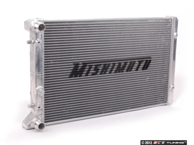
I started with a Jetta3 radiator I got off craigslist for $20. This met the need, but eventually was swapped out for a Mishimoto radiator designed for a Jetta3. This allowed all of the bracketing work I did for the original radiator to be re-used. Sort of. The bracket design was relatively simple: Add a straight square-tube bar across the leading edge of the radiator, and form brackets which are affixed to the bar, but thread into the radiator mounts. The crossbar then had eye-hooks added so the radiator could suspend from the underside of the bus. To the front of the bar, steel security screening was added to prevent refuse from entering the radiator. See bracketing the radiator and Radiator mounting planned for more details.

On the rear, simple individual brackets were formed for each of the 2 mount holes on the radiator. Each bracket had an eyehook added, similar to the front bar. From the 4 eyehooks, the radiator would hang from the underside of the bus. I used 400# test chain to hold the radiator, and placed it at an angle (front about 4" lower than the rear) so the exhaust heat would be encouraged to vent down-and-rearwards and so that the leading edge of the radiator might scoop some air as it passed beneath. Corresponding eyehooks were added to the frame under the center of the bus, and the chains have threaded carabiners on the ends for ease of connecting / servicing. See rad brackets continued and Radiator test-fitted for more details.

To discourage hot air from recycling into the intake side of the radiator, I cut and attached some sides to the radiator unit with some thin zinc-coated sheet metal used as cold-air return material in houses (See Radiator Shrouded). Underneath, I attached an aftermarket fan:cowling to maximize the suction of the fans drawing air through the radiator (See Cowling the Hapy Radiator). For more details, See Radiator InstalledBack to the Bus Rad Swap 1 and 2.

I have not experimented with lowering the radiator beyond it's current height of about 9" above the ground. I had ideas of adding a scoop to the leading edge bar, or adding a means of lowering the radiator with a lever or something, but the bus now runs cool enough without added complexity. If that changes, those options remain.

I know there are some who will read this and not accept that an under-belly radiator is sufficient. Consider that the Aussies are doing it, and were doing it well before I started my project. They have super-hot, dusty conditions and they drive their under-belly conversions in the outback. So, some gravel from the road or a mid-western summer are not really the factors we may fear them to be. After 10 years, these have not influenced the cooling at all. The keys to keeping the temperature controlled are getting the exhaust air away and getting air to draw through the radiator through cowling and fan suction.

Overflow Bottle
The overflow bottle for the NewBeetle is shaped like a ball with a mounting tab on one side, like in the picture here. That tab has the 2 mount holes. I built a simple angled bracket that aligned with those 2 holes, and attached it to the front-to-back floor support at the front right corner of the hatch I added. The bottle needs to be located height-wise in the same relative position as it appears in a stock TDI install. This places the full line at the top of the head. This height requirement may force you to put in an access hatch just so you can add coolant. I suppose a port-hole could work. Your bus, your choice.

Hoses
Unlike the inter-cooler and vacuum, the cooling system left only a few pieces I could re-use. The runs to/from the radiator were solved with multiple 2' long Goodyear flexible hoses fitted together with metal connectors. These flexible hoses satisfied the run from the engine bay to the radiator, but within the engine compartment, there were other considerations. For example, the outlet from the thermostat housing exits the engine pointing at the passenger-side rear wheel. This needs a 90* downward bend, so I used a short piece of original hose, and mated the bend to the flexible hose with a metal joiner that included a small (1/2") "T" which I routed to a bleeder. I have used this bleeder to get air out of the system while filling with coolant many times. The run from the outlet flange also points to the passenger side, and it needs to include a temperature sensor. So, again, there is a mix/match of TDI hose, a piece of TDI plastic holding a sensor and the flexible hose.

I omitted the EGR, so the plumbing around the EGR needed to be eliminated as well. This actually simplified some of the paths. Last, there was the coolant line run to the overflow bottle.

Extras
nicked from TDI-club
I haven't introduced any changes to the oil cooler nor the oil-to-coolant exchanger, but this feels like the right spot to mention it. I have thought about swapping out the original stock TDI exchanger for the V6 4motion Passat oil cooler or the late model NewBeetle / Jetta / Passat / Toureg (also Audi) oil cooler. Both are larger, and with the amount of concern I've had over temperature control over the years, this is an upgrade I will probably do as part of a Malone tune. The V6 4motion looks a lot like the TDI one, just a little bigger while the later model cooler has the coolant inlet/outlets oriented differently (middle unit in the picture). I got these part numbers from this thread on the TDIClub and only re-post here for my own future reference benefit. The TDIClub thread author (Kennedy) deserves all the thanks and praise for assembling this detail.

V6 4motion Passat
028117021E OIL COOLER (should come with upper gasket)
038117061 LOWER COVER TO OIL COOLER WITH SEAL
*I believe the original lower cover will fit, but I'm not 100% sure

late model
038117021B OIL COOLER
038117061 LOWER COVER TO OIL COOLER WITH SEAL
038117070B SEAL

Heater
image nicked from theSamba
For some, having a heater isn't an extra. Its mandatory. I wanted to remain stock-VW parts as much as possible, so I looked into a real defroster-type heater unit. I couldn't fit anything that big into the space I had, so I bought a used Vanagon rear-seat heater. I plumbed that into the heater/defroster hose loop, placing the heater unit on the extra battery tray, under the spare tire well in the engine compartment. This actually worked fairly well. The coolant lines were very short, and I was able to route an insulated flexible air hose to the front, connecting it to the original bus air system. I removed it all when my original ignition went up in smoke, and now don't have a heater. More importantly, I don't have a defroster. In retrospect, I probably could have retained the heater, and just sourced the 12V elsewhere.

I have considered adding an aftermarket heater closer to the front of the bus, and running longer coolant lines to support it. The long air hose system was slow to respond because the air in the hose needs to warm up or cool down before you can feel the change. That's the beauty of the modern systems: no air hoses. The coolant, however, could cool off before it gets to the front of the bus, and there are would be a need for a bleeder, etc. so this isn't exactly perfect either. So, as much as this is a retrospective, some things clearly aren't really done.

De-Scale
Regardless of what you do, if your engine isn't new, and you don't really know how well it was maintained by the prior owner, it might be wise to de-scale it before you consider your system complete. I ran a Thoroflush procedure and that made a massive difference in the bus' ability to ditch heat. Check out the Now Water-COOLED post for some more detail.

Prior related posts:
Preparation
Fuel System
Physical Mounting
Vacuum System
Air, Inter-cooler and Exhaust
Primary Electrical

Next related posts:
Secondary Electrical
ECU, dashpod and Sensors

Tuesday, October 15, 2019

Adventures with Nemo

No, this isn't a post about a clown fish. Today, I'm going to cover the adventure of trying to get Nemo, T's A4, to operate correctly again.

Break Down
This story actually starts very soon after the last post about A4 ended (See A4 Puzzles). It was late Summer, and T had been living with us for a while. His car had been behaving well, but he wanted to make sure everything was tip-top before leaving for Eugene. Well, we got it running, but he broke down with a coolant leak on the way to Eugene. We knew the radiator had a small leak, and we concluded that the leak was the cause. I drop-shipped him a replacement which he installed in his garage. Unfortunately, this was not the cause of his coolant loss.
T replaced the coolant outlet flange. Twice.
He replaced a few hoses.
He swapped the coolant overflow bottle with a used one from the junk yard.
By the end, he was no longer seeing coolant puddles appear under the car, but when he would return from a drive the coolant bottle would register below "MIN". Frustrated, he had the car towed home, to Beavo. He rode with the tow truck driver and borrowed Flash while K2 and I assured him that we would find the cause and fix it.
That was in June.

Rad Patch
K2 was out of school and missing his daily shop time, so we thought he would get into fixing the A4. Well, that didn't last very long as Summer brings its own distractions and rewards. So, while he took some air, I re-assembled what K2 had started (he was preparing for a head-gasket job) and got Nemo to start again. I had forgotten that I had drop-shipped a radiator down to Eugene, so I started to disassemble the front to remove it. I discovered that one of the fasteners holding the air conditioning condenser to the radiator was a screw instead of a bolt. AND, the tip of the screw had pierced the plastic side-tank on the radiator, causing a leak. So, I started with that.
I used an old Shade Tree trick for small (read: pin) holes. Do NOT do this for a hole of any significant size because the superglue could get inside the radiator rendering it less effective or even completely ineffective. Anyway, the quick fix for tiny holes:
drain the coolant down below the small hole and make sure the area is dry.
rough it up a little bit with sandpaper or a file
apply superglue, covering the hole
dust baking soda on top of the superglue, completely covering it
once dry, blow off excess baking soda
fill system with coolant/distilled water mixture and pressure test
Yes, it actually works. Again, this is only recommended for very small holes. There are epoxy-based kits that are designed for larger holes. At some point, though, even those become ineffective and you need to replace the whole thing.

Puddles
This worked great. No more leak from the radiator. But other puddles still appeared after a spirited test drive and the coolant in the bottle read below "MIN". Well, that's familiar. In fact, it is the exact experience that T was having. At least we're back to what he was seeing, and the pin hole in the radiator was not the cause. I found the coolant dripping from the lower radiator hose, which appeared to have been replaced with one from NAPA. I replaced it again with a Continental hose, and cinched the hose clamps down nice and tight. Another spirited drive and another drip-drip-drip, landing in the same spot. I could hear a "pssss" sound, and traced it to a hose near the intake where I could see water bubbling around it. I tightened it up and then started tightening every hose I could reach. I tightened the thermostat cover as well.

Temperature Sensor
During my early test drive, I noticed that the coolant temperature gauge wasn't working. This is often diagnosed as the sensor being bad. I knew we had recently replaced it, but I replaced it anyway. That didn't fix it. While installing, I noticed that the 4-plug socket that plugged into the sensor had a frayed the brown wire. When I tested continuity between that wire and the other end of the gauge-sending side of the socket, I got continuity at the wire (which had a bare spot), but not at the socket. So, I knew the socket was bad. But, where do you find a 4-pin socket with the correct alignment grooves? On eBarf. I cut off the old plug, leaving a short length at the socket for reference and as much wire in the loom as I could. One at a time, I checked and re-checked as I connected the wires with crimp-on butt-connectors and then heat-shrink'd the connections. It plugged in easily and with the hoses tightened, it was ready to test drive. If you replace a plug like this, take care to wire it correctly or you could fry your ECU. No, I didn't, but I was full-on scared about it until I turned the ignition to run and saw the coolant temp appear on my OBD-II reader.

Leak Free
I took a familiar drive up the connector streets onto the main road, thundered down that main road, right at the major intersection, around the next main road to the connector streets on the other side of the neighborhood before returning home. This route has stop and starts, speeds up to 45mph as well as lots of turns and speed bumps. All while remaining within 1/2 mile of the house. By the time I got home, the temperature had gotten up high enough for the thermostat to open. I backed into the drive, pulled the hood latch and hopped out. I couldn't hear any "psss" noise and there was a single drip from the lower radiator hose. I figured that drip could have been residual from prior leaks, and a longer test drive was needed before I called it fixed.

Coolant Bottle Swap
I decided to replace the coolant bottle since I knew the one that was in was not exactly right. The bottle fit the mounting points, but the low-coolant-level sensor was rectangular instead of round, so the sensor wasn't plugged in. When you know you have a coolant leak, that's not a good set up. I drained enough coolant out of the old bottle so I could swap them out, but I did not fully bleed the air. Once re-filled, I got distracted, and left it filled, but un-bled.

Another Drive
The opportunity for a longer drive appeared the following weekend when T stopped by after helping his mom with some chores. He was eager to see how Nemo was progressing, so we pulled him out and took a drive, T behind the wheel. T was thrilled to feel the big turbo spin up (PO upgraded it) and hug the turns (PO upgraded suspension too). By the time we got home, we had been running at normal temperatures for probably 10 minutes. When we got home, we both realized that we couldn't smell coolant, and I mean not at all. Not a whiff. All prior drives had at least a small smell, so this was a really good sign. We popped the hood and saw that the coolant bottle was down to just above MIN. Recognizing this could have been because I failed to bleed the air, we figured we would wait until it was cool again before checking. We also discovered that the tail lights were not illuminating with the headlights. I'll need to fix that before T takes the car back to Eugene.

Bad News
So, I seized upon an opportunity to drive Nemo when I had to take a run to Tualatin. That's a 20+ minute drive with a mix of highways and surface streets, so it would be a good test. When I arrived at my destination, the coolant bottle was pretty much empty. I let the car cool down and then added some water, and drove back home. When I got home, the bottle, again, was nearly empty. I wanted to prove that the system wasn't leaking. So, I grabbed my MityVac. When I removed the overflow bottle cap to refill the water, I could distinctly smell exhaust as the pressure released. I was starting to conclude that the head gasket or head were allowing water into the exhaust. To confirm there were no other leaks, I removed one of the hoses from the bottle, plugged where the hose came from and applied 14psi of pressure to the cooling system. Over the course of several minutes, the pressure would drop by 1/2 psi, and no coolant was appearing anywhere. More reason to believe the coolant is traveling into the combustion chamber. So, my next task, which I will document separately, will be to remove the head, have it tested and then replace the head gasket.

This is a big job. Just for context, I got a quote from a mobile mechanic I've never used, and he came back with $1250US. Seeing that the quote is more than we could get if we sold the car if it didn't have this problem, we're doing it ourselves. Well, myself. I really would rather not spend my autumn working on the A4. I would rather combine efforts with C and dedicate ourselves to the Zed (1979 280ZX), completing the sand-down and possibly spraying primer before the temperatures get too cold to paint. Oh well.

It has been unseasonably cold for more than 3 weeks (10F* / 6*C or more below average), so the window for spraying primer may have closed and it may make the Nemo work a little less fun. Regardless, I probably will not have much time to get back to Hapy until dead-of-winter. I may delay the electrical re-do I had in mind and focus instead on recovering the front seats, since I can do that indoors where its warm and dry. We'll see how I feel and how the weather behaves when the time presents itself.

Thanks, as always, for following along.