Showing posts with label electric. Show all posts

Tuesday, August 11, 2026

Entrenched

It's been a couple of months, and busy ones at that, so today's post will be a bit of a mish-mash covering the highlights.
 
Farm House Fireplace
fireplace surround primed
First, I am realizing that I never posted on our idea to change a blank wall in our living room to have a fireplace. We live on a street with overhead power lines, and we lose power once or twice a winter to ice and wind. We sourced a (Valon H5) gas fireplace and had it installed against and in the middle of that wall in March or April. Being near the end of the cold season, we only fired it up a couple of times. It does not have a fan, so we will be covered in an electrical outage, but we were impressed with how much heat it produces at a low setting and how far from the unit you can feel the warmth.
 
After absorbing that cost, we got our contractor friend, Ray, to do the side job of putting some kind of built-in around it. He did that work a day here and a day there, ultimately finishing at the end of July. I spent this last weekend doing the paint prep and brushing on a coat of primer. I expect to return to that work in a couple of weeks, sanding the primer fixing all the little holes and such that I missed and then applying more paint.
 
Shop Progress
closest thing to "before" image
In an inspired moment in late-July, I emptied the black rolling tool cabinet, pulled it across my hard-as-a-rock clay backyard and into the shop. Once there, I vacuumed it out, Armor-All cleaned it, set it in place and then returned its contents. That represented the last of the things that needed to move. I since have worked through most of the heap, putting like things together on shelving.
 
Electric Hum
While Ray was working on the built in, we noticed that our main electrical panel would hum when his air compressor fired up. We thought that was probably not good and showed him. He agreed and soon we had his go-to electricians over to see what we had going on. The humming breaker ought to have flipped, not hummed. So, soon we were getting the main panel replaced and some outlets fixed and some other lighting things solved. Once we were in that deep, Boo asked them what the incremental cost would be to running electricity out to the shop. Love her. They made us a great deal ($1600US for an active circuit, 60-amp sub-panel wired from the main through conduit in the trench), but the numbers hinged on the trench being dug, and the work starting about a week later.
 
Trenching
cave-in at the turn
This is the lead-in that found me running a 24" trencher on a Monday morning. The weekend before I had cleared all the mulch and other undergrowth, shrubs, etc along the approximate 100' path. I also needed to hand-trench around the french drain I had installed around the shop last summer. Once cleared, I marked the future trench line with spray paint. I rented a trencher from HomeDespot, not because I love that store, but because they had the best-by-far price (like half what everyone else offered) and they would deliver /pick up. So, with that trencher, I dug 100' of 24" deep trench. Considering how many Holly trees, wild roses and other things we have found in this yard, I was prepared for a long difficult day.
 
The trenching started difficult enough. I thought I would do the line from the garage down to the 90* turn south first. That meant starting the trench up against the garage where I found the first foot below the surface was bricks and chunks of concrete. Fortunately, once I was able to get that cleared, the rest of that east-running line was uneventful. I got as far east as I could go, setting my back up to the neighbor's fence and then wrestled the machine to face north. These trenchers do not turn at all easily, you have to muscle them by lifting and shoving. So, once facing north, I started trenching southward, leaning and pushing west to offset the slight pitch of the yard.
 
future trench line
The next 40 or so feet (almost 15 meters) were efficient. I did not hit big roots until I got to the apple tree just outside the shop's main door. Even then, I only need the sawzall to cut a pair of thick roots. The trencher took care of the rest. Once I got to the 90* turn west to get to the shop wall, I wrestled the machine so I was facing west, moved it up to hand-trenched section and ran it east until I hit the fence. Similar to the other end of the long trench, I could not connect the big trench with the shorter sections without trenching in both directions. This meant wresting the machine over a trench at some point. Inevitably, those moves caused cave-ins. Still, the main trench work was completed, so I ran the trencher out to where it was dropped off at the start of the rental and hosed it off.
 
After work on Tuesday, I was out at the trench with a disposable plastic "go food" container, hand scooping out the cave-ins. I discovered that my last "cave in" was actually an incomplete trench where it turned 90* south near the garage (see 3rd picture from the top). I had to finish that trench by hand. It was at that point that I really appreciated the trencher. The clay soil in the backyard is as hard as a rock at this time of year. So just clearing less than a foot deep, maybe 18" long trench was a considerable effort. I was already beat-to-shit from wrestling a trencher in nearly 90*F (32*C) heat the day before and Tuesday was just as hot.
 
black "rollie" in the shop
We passed inspection for the trench this week. So, I will be filling the trench back in and then I will be able to move cars in and out of the shop again. While I did not plan to lose access to the shop this summer, I am so grateful for having electricity, even if it is just a sub-panel with no outlets nor circuits. We will be that much closer to having lights without depending on a partially buried 100 foot extension cord running from the old garage. And, once the trench is filled back in, I only would have had the path blocked for maybe a month.
 
We had a different inspector than we have had with our other inspections. This guy was a bit of a hard-ass relative to the others and inauthentic. I only bring that up because what he said to me and what he put into his report were not the same. He said everything was good except he needed some detail around a ground for the water heater (which wasn't in the scope of the work, but whatever). The report identified a bunch of other things that he never mentioned and were also outside the scope of the work performed. Needless to say, I'm unimpressed and hope he doesn't inspect anything around here again. I would have no reason to trust what he says, and expect him to add things to his report after leaving, including things which may have nothing to do with what's within the scope of the permit. Inauthentic sucks.
 
Wrap 
This got long, and I never got to any car stories. There are a few. I'll post on them, and whatever new ones happen, next time. Thanks, as always, for following along-

Tuesday, February 13, 2024

NewOld Kitchen progresses

Quick check-in post today on the state of the kitchen. Most of this work is being done by others while I work my 9-5 and then Boo and I clean up or move stuff around on the evenings and weekends. The construction has been moving at an incredible pace after so many months of seemingly slow-go. To be fair, I was only really getting after it on weekends versus a crew working multiple days. So, it's probably not fair to me to compare. On the personal side, my band's EP (find detail here) released on Groundhog's Day (2-Feb) and my sister came to visit for the following week. 

Where Were We
current state
Once the floors were finished, we could get moving forward on the kitchen. Consider, we have been living without a kitchen for about a year. Instead of a kitchen, it has been a version of an efficiency apartment where we have a fridge, but only a crockpot, a single burner hot plate, a microwave and a hot pot for making food. I suspect most folks, at least Americans, would have lived on take-out food. Had this project only lasted a few weeks, we might have gone that route. Into our 12th month like this, however, yeah, we could not afford that. After the plumbing work I described last time was completed, our electrical rough-in was done by our friend Gary.

Electrical Started
For electrical, we simply focused on the "sink wall", making sure we had juice where we needed it for the dishwasher and disposal, as well as some over-counter outlets. Last, he ran a line for task lighting over the sink. Since that initial work, he returned to run the 220V for the wall oven and the 110V for the fridge. He will return to run lines for the stove and some additional outlets.

Drywall and Cabinet Set
rough plumbing done
With the electric on the "sink wall" done, Ray, our general contractor was able to get the drywall repairs completed. This included some of the rough bits around the new rear door, the holes for the old furnace location, the false beam where I removed that wall and everywhere else in the main kitchen space. Once drywalled, mudded and sanded, they primed and then painted. Once dry, the "sink wall" cabinet was cut down to fit the dishwasher, and both were set in place. They continued by installing the pantry cabinet and fridge, and then the cooktop peninsula. The cooktop peninsula, similar to the sink wall cabinet, was cut down to fit our space. Again, most folks design and buy cabinets to fit the space. We bought and are customizing. Considering the cost of new cabinetry, both in terms of dollars and environmental impact, this path is far less expensive on both counts.

So we could get a sense of the workability of the space, Ray cut down some 3/4" plywood for countertops and pin-nailed them into place. The cabinets along the once-furnace-wall have not been cut down and installed yet but already it feels like there is considerable space to work in. We have not had a kitchen in a while, so it is more pronounced for us, but visitors have made similar observations: for what looked like a really small space from outside, it is looking like it will be very functional with lots of counter space. Boo and I have been calling it the TARDIS-effect. Dr. Who fans unite.

Water and Gas
setting pantry depth
For the water rough-in, the plumber did everything he could that did not require a permit. From that point forward, the work is either mine to complete, or I need to get permits and farm it out. Boo and I decided to split the difference: I do the work, but have the gas plumbing inspected by the gas company. Fortunately, the water is quite simple these days: shut off the main, release the pressure (dumping water down the drain) and do the work. In terms of the work, there are shark-bite valves that are no-solder connections. I simply cut off the closed nipple on the end of the pipe and attached the shark-bite around the pipe. It really is that simple. Once the valves were on, we could re-pressurize the system and check for leaks. Seriously, it was that easy; I have no idea why that part of the plumbing needs a permit while the pipes in the walls don't. 

For the gas line, we ran 3/4" pipe from the "T" near the furnace over to the peninsula in the crawlspace, but did not connect it. Instead, where the union will be, we capped it off. At the peninsula, we necked down the 3/4" pipe to 1/2" per standard to pass through the floor. Above the floor, we added a pressure gauge. All of the joints were coated with pipe-dope, of course. We applied air-pressure into the pipe run (from cap near the "T" to the pressure gauge) to 15 psi to verify there were no leaks. As of the publishing of this post, the pressure is still holding at 15 psi. We did all this so we could document it with pictures for the gas company inspector. We do not have the inspection scheduled yet, but after 5 days of holding 15psi, I think we have demonstrated we are good. I expect to finish the gas line next weekend.

what's next
That's as far as we've gotten in the last couple of weeks. It has been a whirlwind of activity, though. Next up will be the construction of a cabinet to hold the wall oven, installing the oven into that and then installing the cabinets along that wall. We have not made any decisions about upper cabinets in the main work area. At this point, however, we are considering leaving the walls without upper cabinets nor open shelving. We have a cabinet we call "the Archie" that we expect to install next to the oven cabinet (on the all in the picture on the right, here). It is possible that it will be the only upper cabinet. Again, we'll see how it evolves.

Thanks, as always, for following along. Hapy broke his speedometer cable a couple of days ago, so I will be posting on that replacement as soon as I've completed that.

Tuesday, May 31, 2022

Luxury Electrical Restored

As I work through the interior of the 1972 bus, I am learning that there are many layers to the electrical re-visit. I posted about the re-wire of the ceiling circuits (see Ceiling Wiring Rough-In). Today, I go over some of the other modifications I have been doing in the electrical space. I had the interior torn apart, so it seemed like a good opportunity to get after things before I put it all back together again. For example, the cushions have been removed from the rock-n-roll bed, and the cabinets have been emptied. 

Changing Tack
I am absolutely feeling time pressure, as the days get longer and camping season looms. So, I am shifting to getting things good 'nuf for Summer. What does that mean? I am setting aside the headliner. I am setting aside the carpet and the door card stuff. Instead, I am going to focus on getting Hapy operational enough for us to enjoy the Summer. The new reduced scope for the Spring includes the finish electrical (this post), completing the sound deadening (slider door and a few little bits here and there) and getting everything else that was pulled apart put back together. If I have any time opportunities pop up, I will do a little thing here or there so long as it doesn't impact our ability to take Hapy out for a spin or a camping trip.

Furnace Control Moved
Afterburner control
Recall the diesel furnace I added a couple years ago. When I did it, I added a custom computer-based thermostat, called Afterburner, hand-built by a guy in Australia. I had mounted the control unit to the side wall about where the 1979 Westfalia control panel traditionally sat. I decided that I did not need to see the thermostat all the time, and would prefer the less-cluttered look. Also, the LED panel glows whenever there is power (it doesn't have a sleep concept), so at night, it acts like a potentially unwelcome nightlight. I moved that control panel right next to that 1979 control panel: inside the rear cabinet. The wiring was readily available, and simply required another hole to be bored in the wood panel. The temperature probe, of course, needs to be in open space. I had previously routed it up along the C-pillar (between the mid-window and the rear window) and set it sort of hanging on the window frame. Obviously, that was temporary. I am not sure where I will put it now, but according to Ray, Mr. Afterburner, the sensor wire can be extended with CAT5 cable. The extension should work, but if I can avoid adding another variable, I will. Ultimately, I will solve this later. I did, however, run a CAT5 cable from the bottom of the B-pillar back to the furnace control so I could make the modification later, if I so choose.

I discovered during testing, however, that a couple of things are not working properly with the furnace. First, it test-fired okay, and it really pulled the voltage down on the luxury battery. I had forgotten about that, and the fact that I cut off the furnace wire back to the drive battery during the interior tear-out. I will need to upgrade the wiring to thicker gauge to see if that stops the heavy voltage drop, and then maybe re-plumb the wiring to the drive battery. Second, during the test run, it became obvious that the exhaust had become disconnected as exhaust started to appear inside the bus. That's bad. I will need to completely exhume the furnace and re-do the install to make sure there are no leaks. Last, there is something not right with the Afterburner controller. It no longer supports a web access point. So, it has all the other great stuff, but I can't start it remotely. In the end, the furnace will sit unused until I fix the exhaust... and the voltage drop. Maybe I'll figure out what's up with the Afterburner access point after that. Of course, it may be next spring by then.

New Fuse Box
new fuse box
I had been wrestling with a decision about the luxury fuse box for a while. I had been using a spare bay window bus fuse box. It worked well enough, but it was not perfect. It lacked a common positive post, some of the fuses had a common supply side and others did not, and there was a whole relay section that I didn't use. The fuses were the old-style fuses, not the newer bladed ones, and those old-style ones are becoming harder to source, and more expensive. Last, it is kind of big, almost 50 years old and the way I was using it was a hack that would fail. So, I bought a smaller 12-slot fuse box and a master circuit breaker / switch to put between the battery and the fuse box. Since many of the wires were being replaced, and the remaining were going to get at least touched as part of the routing, changing the fuse box was a small incremental increase in scope. I needed to remove the prior box for the noise contain efforts anyway, so I was halfway there already.

Doing the Doing
wire up in process
In the Ceiling Wiring Rough-In post, I described what color wire was going to be used for what. I ran or strung the wires to their destinations, and routed the other end down the driver-side (left) B-pillar, along the front edge of the middle window, under that window around the fridge-cabinet and left things pretty much in a heap right there. I started by completing the routing of the wires along the route that the solar collector wiring ran (See Hapy Gets Solar). I zip-tied the wires together and against the side of the bus and then solar wiring inside the fridge cabinet to hold them secure. Once I determined which fuse spots were to be used for which wire (see below), I mounted the new fuse-box onto the top of the wood box under the rock-n-roll bed which covers the old Westy rectifier.... basically in the same spot as the old one was before.

With the fuse-box in a fixed location, I could determine wire lengths and mount them up. In an ideal world, I would have used ring terminal wire-connectors on the wires. I could not find enough of them on hand, so I just used the bare wires. In classic Paulie Axiom form (See Light a Cigarette, Attract a Bus), I found them after I did this work so I will be slowly retrofitting them onto the wires. Anyway, once the wires were routed, trimmed and connected, I wrapped the bundle in one of those plastic wire tube things.

Fuse Layout
fuse wire color purpose
1 Grey Cab 12V Accessory Plug
2 Purple Cab Dome Light
3 Yellow Stereo
4 White 3-switch Dome Light
5 Pink PopTop Light / 1-switch Dome Light
6 Blue 3-position Westy Light
7 Yellow Furnace
8 Green Rock-n-Roll 12V Accessory Plug
9 Green Sleeping Area Dome Light
10 Orange Sleeping Area USB Chargers
11 OPEN OPEN
12 OPEN OPEN
 
Wait a Second...
wired up
The keen eye will notice that circuit #3 is wired up in the picture on the right, but isn't in the picture above it. Fuse #3 is the stereo. This is interesting only because of the gymnastics I executed to get it there. Before I started the noise project, the power lead for the stereo ran on the floor under the carpet. Yeah, that was not ideal, but it worked short-term. I ran a new power lead behind the dash and through the original wiring harness pass-thru hole in front of the accelerator pedal. From there, it runs along the inner edge of the passenger side frame rail and passes up under the rock-n-roll bed through what looks like a factory drain hole. A closer look at the rear edge of the wood floor will show the yellow wire running along behind / underneath. I didn't stop there, but that's another post I'll write up and post later.

Battery and Ground
Finishing up the circuit, I first confirmed that none of the wires I just hooked up to the fuse-box effectively ran to ground with the multi-meter. I returned the luxury battery to it's old location, and hooked up the ground cable to the same grounding bolt near the fridge cabinet under the seat. With the sound killer installed, it was a little harder to find.

ugly (for now) but functional
My last step was connecting the B+ or positive side. My old set up had many smaller gauge wires all wound together at the battery post. I used a very short stretch of 8 or 10ga wire to bridge from the positive post to a master switch, and then some more of it to bridge from the switch to the fuse-box. The wire was the thickest I had around. I will mind the overall amp usage, but this should not be an issue except for when the furnace first starts up. Even then, I do not expect much system stress. The master switch is a battery/fire-saver, basically, that will prevent more than 100A draw. I don't see this switch ever popping, but it is better to be safe than on fire. Based on the length of the wire, and my uncertainty about it's thickness, it is very possible that the wire will fail before the switch pops. Ultimately, I would need to have every circuit in use and have the furnace kick on to get close to even 50A. So, the switch becomes little more than a means to turn the whole system off.

Completing the Circuits
I had very little in terms of electricity consumers actually connected at this point. So, my ability to test was fairly limited and I only put fuses in the circuits as they were completed. Still, I was able to turn on the light by the front seats, and test the accessory plugs up front and by the rock-n-roll bed. All good. I checked continuity on the circuits which did not yet have a consumer, but I did not really expect any negative findings, and didn't have any. So, I started down the path of hooking up lights.

not as ugly. functional
I started with the light fixture over the sleeping area (pictured above). I used the mounting bolt for my ground, attaching a ring connector to the white wire, and leaving it inside the fixture. To the black and red wires, I connected female wire connectors. My method has been that the power-supply side wire would get a male connector, and continued that throughout. To the green (to fuse 8) and white (to the switch over the slider) supply-side wires I attached male wire connectors. I discovered, as I attempted to install the light fixture, that that 1/2" thick Mega Zorbe sound absorber was too thick for my bolts to reach the riv-nuts. I considered finding longer bolts, but concluded that the heat produced by the light fixture could have a negative impact on the foam, and chose instead to remove the foam where the fixture went. The fixture effectively recessed into the foam, which, I think will actually look better once the headliner goes in. It admittedly looks pretty trash right now. Once the fixture was mounted, I plugged in the wires, and Immediately, the red LED on the fuse-box next to fuse holder 8 lit. This told me that the circuit was good, and just needed a fuse. I popped in the fuse, and the light came on. Sweetness.

so many lighting choices
I followed this same path for the 3-position light over the window behind the driver seat (pictured above)... mounting bolt for ground, male female orientation, even plugging it all in to see the red LED. I needed to add a mounting plate behind the Mega Zorbe, but that was barely post-worthy. I cut out a small section, cut a rectangle of HVAC and screwed it to the bus. I set the fixture where I wanted it, marked and bored the holes. Easy-peasy.

I verified the pop top light at this point, and then shifted to the modified dome light (See Dome Light Mod to Trigger Other Lights). I had tried to mount this light earlier, and the mod wire broke off. I mentioned that in a comment on that original post, but I simply duplicated the effort with a thinner multi-stranded wire. On my repair version, I super glued the wire end down like before, but also added a 1-inch long stretch of superglue to adhere the insulation to the light housing. That bugger was not moving. I wrapped every bit of exposed metal (chair adapters, bits of relay, etc) with electrical tape so nothing would short out after I popped a couple of fuses. Once they were wrapped, and I could get the relay tucked in deep enough, I was able to settle the light fixture into place.

Testing the Lights
Once all of these circuits were completed, I cleaned up Hapy's interior and then hit it with the shop vac. Clean, and de-cluttered, Boo and I tested / played with the lights. The lights up front will work for checking a map or even reading a book. The original dome light, when turned on as a single creates plenty of light in the main cabin to see things on the floor, and even on top of the fridge cabinet. When the modified light circuit is turned on, the entire bus is well lit, from dash to tail gate. Since the rock-n-roll bed is not together, we could not test the reading lights for reading, but that test/play will be very soon.

With the new plan of just getting Hapy ready for the road, I do not feel the same pressure I did before. The lighting is functional, and I learned along the way that I needed to make modifications which would have been unpleasant after the headliner went in. Removing these fixtures for the headliner install will not be difficult either.

Thanks, as always, for following along-

Tuesday, December 1, 2020

Chasing the Hapy Electrical Gremlins (part 2)

Today continues where I left off with Hapy. Last, I had pulled a cable from the rear to the front, through small openings in the frame. I wired up the accelerator pedal plug into the new cable, as well as the ignition switch. Today, we take the next few steps.

Looking Up at 40F (4C)
Yes, it is still cold. It is December, after all. Now that Thanksgiving is behind us, the holiday music can come out in full force. Meanwhile, I'm dreaming of a not-rat's-nest wiring set up. Though, I suppose, a white Christmas would be pretty great too. We start with getting the wiring up front completely tidied up. I wrapped the exposed wires from the cable with 1/2" plastic wire wrap so it remains one cable almost all the way to the ignition switch. I split off the 6 wires for the accelerator pedal from the main bundle in front of the hand brake (front is front), and wrapped that in another plastic wrap. I ran that bundle behind the accelerator pedal support down to the pedal assembly. I then fed the excess cable down through the floor, leaving a little slack in the cable, but only just a little. The work in the cab is basically done for now.

Underneath
At this point, I slid under the front end and started sending cable back towards the rear. I was only able to get about midway before the original wire clump started to become a problem. See, I reused many of the same pass-throughs that I had used 10 years ago, and pushing the cable back against these wires was really not happening. So, recognizing that the old wires are no longer needed, I removed them. Unfortunately, they were taped to the 4-wire bundle for the brake switch, so I needed to remove that bundle as well. I wasn't using that circuit anyway: it only serves to notify the ECU that the brake has been pressed so turn off cruise control. I am obviously not using cruise control, so all of those wires go. I cleared wires all the way back to the spare-tire well, and confirmed the wire colors on the accelerator pedal circuit: they match. So, while the plug changed after the 1998 New Beetle TDI implementation, the wire colors didn't. Neat.

Lower Rat Nest Tear Down
Original outlet flange
Way back when I first did the swap, I had a Vanagon rear seat heater sitting on the accessory battery tray. That heater blocked from view how bad the wiring snarl was un the engine bay. Once the heater was removed this past Summer, it could have been obvious... if I'd looked. I did at this point in this rewire, and chose to start the cleanup right there. Hidden behind the heater were the relays and other associated wiring for the coolant glow plugs. For those not in-the-know, the manual transmission TDI's delivered with an aluminum coolant outlet flange. That flange had 3 glow plugs to warm the coolant. This flange was on this engine, but the coolant outlet sticks out the wrong side. In the bus, it sticks into the fuel tank. So, I swapped it out for the plastic coolant outlet flange that routes to the sides. Anyway, all that extra wiring and relay box were just sitting there. Were. They have been removed now. I moved a couple of ground wires that were in the middle of everything and then took all of the other wiring and pushed it up through the hole into the spare tire well. The cables that remain in the engine compartment are mostly against the compartment ceiling now. I didn't do much more, because I want the wiring up above to dictate how much more I do.

Research Again
It has been 10 years since I really looked at this wiring. Fortunately, TheSamba contributor AndyBees sent me a tome of wiring knowledge back then, and since I did not meaningfully stray from his work it will very much help me now. I barely scratched the surface of this documentation when I first did this install, though I did keep it in a 3-ring binder, with the other bus books in Hapy. 10 years ago, my goal was to just get it working and then I planned to circle-back and improve / clean it up. Well, after years of wrestling with the coolant (first leaks, then overheating) and then needing a break from the bus (hence, Oliver, the 1978 MGB), I'm only now getting to this. Based on a few hours of study, I expect I will be able to significantly reduce the remaining wiring. For example, I still have relays and wiring related to the radiator fan controls, even though I have those fans on a dashboard switch. And, of course, I will not be doing cruise control. There will be other discoveries as I go.

This is as far as I've gotten. My next steps are to start eliminating wiring related to functionality I am not going to retain (cruise control, etc). Since Hapy is outside/carported, this may take a while as I wait for nicer (read: warmer) days. We usually get a 50F/10C-degree day here and there. Since Hapy is blocking the garage bay where Oliver is parked, I may get my wrenching fix with some little projects on him when the weather is too cold to play with Hapy. Time, or more like weather, will tell. Thanks, as always for following along. Please stay isolated, and wear your mask / wash your hands when you can't.

Tuesday, November 24, 2020

Chasing the Hapy Electrical Gremlins (part 1)

In the Summer of 2019, we barely made it home at the end of the Dog Days 333 (See parts 1 and 2). Hapy decided to just not start on command anymore. He was dropping into that modified limp mode and it was happening not just when he was cold, but pretty much at random. I promised him that I would fix it as we sat idling in a Dundee convenience store parking lot while C was in getting us drinks. Today's post starts that "fix it" journey. Before I begin, for my US readers, Hapy ThxGiving. For CoViD's sake, please stay home.

One Last Time
Hapy parked in tarmac spot
Hapy's usual home
After I finished the priming of all the Zed body panels (See Zed Prime), I moved them into the garage. This freed a covered one-car parking space. I had initially planned to put Nemo back in there and get after his wheel bearings. I decided instead that with the CoViD-19 numbers climbing to all-time highs, maybe it was okay if I didn't have a car that could take me too terribly far. Nemo can get me to the corner store and back; that's plenty until I can get the wheel bearings done.. once I confirm that they are the source of the noise, and it isn't just loud tires. So, I switched it up, and I am instead jumping into the Hapy electrical. I could have gone after this stuff at any point during the nice warm summer. That just wouldn't have been consistent with all the other work that's been done on this beast, so of course instead I chose some of the coldest days this year to do it.

First, I had to get Hapy into the spot. He is usually parked on a tarmac strip at the curve of our driveway so we can see him out our bedroom window. Yeah, we're weird. For any other car, moving it would be a simple effort of start, drive forward, reverse into the spot. Once I got the other cars out of the way, it was his turn, and just like so many times before, he just didn't want to start. I turned the key to start and nothing happened. Sigh. So, I tried to push him. Nope. There's a little dip in the tarmac that he would roll back into. I had to pull him onto the concrete with a trucker's chain around his front sway bar at one end (his front tow hook was pancaked by the prior owner) and around Nemo's front end on the other end. Fun. While I was trying to figure out how I was going to push him back into the covered spot, I lamented out loud to Hapy "why can't you just start one more time?". His response: he started. Of course; good boy. So, I backed him into the covered spot, and turned off the key.

Running Cable
In the TDI retrospective about secondary electrical, I mentioned replacing the single wires I originally installed 10 years ago with a cable. Well, I bought 30 feet (~10m) of 12-wire 16ga cable for this job when I bought cable for the additional gauge (see Oil Pressure and Temperature Part 4). It is not quite as thick as my ring finger as a sealed cable, and it has a nice thick jacket on it. I figured that the computer and rat's nest wiring is on the driver (left) side, as are the accelerator pedal and ignition switch. So, running the cable along the driver side made more sense than running it along the other side. Turned out, I thought the same thing 10 years ago, as the old wire bundle ran that way. I started from the rear, threading the cable through the bottom of the spare tire well and down into the engine compartment. From there, I ran it through manufactured holes in the frame over the rear suspension, along the inside of the mid-section frame rail to the cross member near the new heater location. I pressed the cable through a square hole in the cross-member, under the brake booster and then through another square hole into the area covered by the front belly pan. I had bored a large (~1/2 inch diameter) hole at the very front over the Summer when I routed the heater fan control cable through. I had planned to reuse that hole for this cable, and it fit with very little trouble. I pushed and pulled about 5 feet of cable up through that hole so I could stand alongside the driver seat to do the wiring bits.

Wire Front First
The 12-wire bundle is more than I was really ready for. The accelerator pedal needs 6 of them. The start and run signals account for 2 more and the OBDII signal is the last. The other wires will be used in the future for things like a speed sensor and a glow plug light. Like the extra wire in the cable I strung for the oil temp and pressure for a low coolant warning, I'll get to those later. For posterity (and my own personal reference later), these are the circuits for the 12-wire cable. I will update this as I make changes or discover mistakes:

circuit wire color purpose
1 Red Accelerator Pedal 1
2 Yellow
Accelerator Pedal 2
3 Orange Accelerator Pedal 3
4 Brown Accelerator Pedal 4
5 Blue Accelerator Pedal 5
6 Black Accelerator Pedal 6
7 Red/Black Ignition - START
8 Blue/Black Speed Sensor
9 Orange/Black OBD-II
10 Yellow/Black Ignition - RUN
11 Brown/Black Glow Plug signal
12 Black/Red OPEN

I started with the ignition, splicing into the existing "RUN" circuit with the new signal wire. I figure the existing stuff (like lights) need power too, so the existing wire will simply feed old circuit #15. For the "START" signal, I just ran the new wire. The old starter signal was pretty batty, but it proved the TDI install was viable. Recall, it ran from the ignition down the old wire to right near the starter where it was spliced into a new wire that ran around the engine compartment to the spare tire hole through a relay to the computer, which then signaled TDI-donor relay to fire the starter... thru a new wire to the starter solenoid. There's like 20' (7m) of excessive and old wiring that I can eliminate. Then, I moved to the accelerator pedal.

Now, recall that I had to swap out the original round-plug accelerator pedal plug with a newer-model flat one after the old fly-by-wire pedal started to short out. I took a picture to help me identify which wire is which at the other end, but because the plug was changed, I expect the wire colors were as well, so when I cut the old wires off, I left about 1/2 inch of flat-plug wire on there so I can compare with the picture (here on the right) when I get to the rear-end wiring.

EDIT: I have updated the picture on the right here and the wiring reference above to reflect the actual circuit numbers in the wiring diagrams to avoid any confusion. Originally, the numbers ran the wrong direction relative to the official wiring schematics.

Even without the change, it was important to consider placement of the cable and the things that were going to be wired into it when I made my cuts to the wires. The ignition, speed sensor, etc are all at the dash where the accelerator is at the right foot. I made sure there was about 3 feet (1m) of cable between the ignition and the accelerator pedal cuts so there is room for cable routing. Also, it was important to pre-route the cable as much as I could so we didn't end up with the cable running in front of the steering column or goofy some other way.

Next
I admit, that doesn't sound like much. I moved the bus, ran some cable and did the wiring at the front end. Still, in sub 40*F (4C) it was a feat getting that much done without going numb. The weather around here is decidedly cold. I accept that I will not be able to get things done on Hapy very quickly, but with him out of the rain, at least it is not completely miserable. Just cold. If I can stand the cold, I will finish up the wire cable in the front by wrapping it with some plastic wrap, and pressing the excess cable back into the belly pan. Then, I'll push/pull the excess back to the rear so I have room to wire up the controls back there, probably leaving me close to 3m of leftover cable. There is a great deal of electrical housekeeping that I have not done back there. I think this is the right time to clean all that up, removing the unnecessary, trimming and mounting, etc so it is nice and clean. And, or course, our sporadic modified limp mode will no longer appear. It's all about staying warm enough to take small steps forward and eventually the wiring will be done. Then, I'll switch to diagnosing Nemo's rear bearings again.

Thanks, as always, for following along. Posts may appear more slowly as my work slows down. I'm still working on it (and staying CoViD safe, of course).

Tuesday, January 14, 2020

TDI install retrospective: Secondary Electrical

Continuing the process of back-documenting what I did to put a TDI engine into an old (1972) air-cooled VW bus. Today I cover what I call the "secondary electrical". This includes everything that isn't responsible for the alternator:battery:starter system. So, this is the radiator fans, the accelerator pedal, the OBD-II plug by the driver seat and any other miscellaneous stuff I can think of.

This is the first post following the announcement of Neil Peart's death, and I can't let it pass without expressing my heart-felt loss. I love Rush and wish Getty and Alex my deepest condolences. With 2112 blasting in my ears, and "with hungry mind and open eyes"... we return to the TDI retrospective.

Random Cables
Beyond the core primary cables, there are a few thicker wires that need to be run between the relay bank and the battery-top fuses. For these, I found wire of the same thickness, and ran them through the hole in the spare tire well, along the top of the rear engine hatch to the battery-top fuse box. This pathway became fairly well used for sending wiring from the computer to the sensors and senders around the engine. To enable that, I expanded the hole from a tiny drip opening to a 1 inch by 2 inch rectangle.

Cooling Fans Circuit
old NB pedal on left, brake switch on right
I had originally tried to re-use the TDI-stock thick relay and control module to control the radiator fans. That was a mess, and didn't work, so I ripped it all out. Instead, I used one of the small battery-top fused circuits for a power source and a switch on the dash to trigger the fans. The switch went into a hole in the metal dashboard that had not been exposed through the vinyl cover, right next to the ashtray. It receives power from an always-on source so I can cool the radiator even when the engine is off. It triggers a standard relay mounted next to the radiator on the passenger side. When triggered, the 12V from the battery-top fused circuit sends 12V to the radiator fans and the little fan on the inter-cooler. This is a simple circuit, but I have found that long bumpy road trips cause the clips to slowly shake off the relay. So, I may need to put a dab of threadlock on there to stop that.

Accelerator Pedal
new pedal
I originally used the accelerator pedal from the NewBeetle (NB). This was a one-year-only part, so when it eventually failed I had to either pay a few hundred dollars for a replacement or swap it out for the more common pedal. The challenge with the more common pedal was that the rheostat was integrated into the pedal body, so I couldn't hide it like I had hidden the NB pedal. The NB pedal had been stowed inside the belly pan, and allowed me to continue to use the original bus pedal. The integrated housing style pedal meant that the entire pedal would be changed, and it would need a support. I still don't like the final look, but it places the pedal in the right spot for my foot, and it drives correctly. The wiring was fairly easy. There are 6 wires attached to a flat pigtail. I extended the wires and ran the 6-wire bundle under the bus from front-to-back, arriving in the spare tire well, and wired into the computer where the pedal originally wired in. I believe I used wires that were just a bit too thin, because I get sporadic limp-mode issues from lack of signal from the accelerator pedal. See Pedal on the Right for details on the install.

Brake Pedal
NOT USED. If you intend to use cruise control, the computer needs to know when the brake pedal has been depressed. I thought about tying into the brake warning system or putting the sensor on the master cylinder. Ultimately, I made a little bracket on the arm of the brake pedal and the switch triggers when I step on the brake. I don't use cruise control, so I've kind of forgotten about this pedal. 10 years later, this may not work at all, so be advised, this may not be a viable solution. You can see a picture of my switch above. No, it isn't pretty, but at the time it was functional.

Fuel Level
NOT DONE. The range of allowed values for the fuel level gauge in the bus is quite different from the range for the TDI. If you want to swap out the original sender, I found one that would work at Summit Racing. I had thought about building a circuit which would translate the reading on the stock sender into the range accepted by the TDI computer, but I shifted onto other things. My thought was that the original gauge could still work, or I could reference what the computer thinks. I may still do this, or just buy something that does it, like the SN34 from Classic Instruments. For now, I am using the stock level sender and gauge; the computer has no idea how much fuel we have. Most of the time, I don't either.

Speed Sensor
NOT DONE. There are a few ways to go after this. I started down a few paths and decided that I didn't need for the computer to know how fast I was going, so I stopped working on it. My first stop was to try to adapt the vehicle speed sensor (VSS) from the TDI. I couldn't figure that out. So, then I looked into getting something that fit between the dash and the speedometer cable. This looks especially promising as there is a company in Britain (RJ Engineered Solutions, VSS link here) that makes a thread-in plug that fits into the back of the speedometer that the cable threads into. It produces a square wave the computer can understand. While writing this post, I ordered one so I could complete the experiment later. I'll post about my findings once I have some. Since I first investigated this, there are more plug-in options (like Dakota Digital), so you may find something that better suits your project than the RJES solution. The last option is to build your own Hall Effect (or other) sensor. Whichever way you go, Dakota Digital also offers a small magic box (SGI-5E Universal Signal Interface Unit) that can adjust the signal from the sensor to the ECU so you can account for a signal mismatch or simply because you got bigger tires... like I did.

OBD-II
UltraGauge
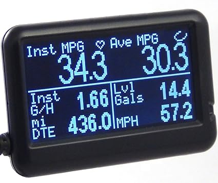
Since I decided against retrofitting the Beetle dash-pod into the dash of the bus, I still needed some engine monitoring. The old bus had 2 lights for monitoring: one to tell you you're out of oil so your engine is toasted and the other to tell you your electrical is shot. Ultimately, your warning system is your ears. Good thing the radio is so lousy, or not there, so you can hear the clamor from the engine bay. That model doesn't work for the TDI: you can't hear a coolant leak or overheating, and by the time you hear the result of the failure, it's too late. So, I extended the signal wire from the OBD-II plug from the rear of the bus to the front by the gearshift. I got a generic OBD-II plug off eBay (it's new, I just avoid Azn) that only had 3 wires: 12V power, ground and signal. The first 2 were easy, wired the 12V to a switched circuit (15) and grounded against the dash. For the signal, I traced the signal wire on the generic and determined which wire from the stock plug matched it. I know that sounds improbable, but it totally worked. Back then, there weren't the BlueTooth OBD-II readers around today. I got a wired one (UltraGauge) for around $80US that's about 1.5 inches tall and maybe 2.5 inches wide that I have jammed into the corner where the dash meets the driver-side A-pillar. I set the screen to show me engine temp and RPM's so I can watch the 2 things I care most about. I love/hate that thing. The longer I go without a coolant temperature issue, the more I realize just how much that $80 gadget saved my engine.

Along the way, I got a ScanTool OBDLink LX thinking I would integrate a more sophisticated graphical dashboard. It is pretty clever, and with a small tablet, a fuller engine monitoring capability is there for the taking. For me, it doesn't make sense until I have the fuel level and speed getting sent to the computer, so the tablet dash will wait.

Heater Fan
I had heat, but when I had my ignition fire, I removed the electrical parts to reduce the load on the circuits up front. If you intend to wire fans for heat, I suggest you find a strong source of 12V power and use an isolated circuit for it. I would just check the power draw for your fans and plan accordingly. You don't want to blow an important fuse because you kicked the fans onto high. I know I will be doing something to restore a defroster at least. I will probably source power from the battery-top fuses rather than the original bus fuse box and then use a new switch rather than the original Vanagon rear-seat heater switch. Because I already have it in-hand, I will probably re-use the Vanagon rear-seat heater unit, though. I'll just need to figure out where to locate it closer to the front of the bus without appearing in the passenger compartment.

Un-Rat-Nest Wiring
I have done this a few times and still need to do more. Unlike all of the other things on this project, this one is most like cleaning your shop or going to the dentist: you never feel like it, but you're so grateful you did afterwards. The original harnesses are not length-appropriate for this application. Along the way, we extended the ones we needed to extend. This step is about shortening all the others so you don't have a big old rat's nest of wire. I have sourced a relay block to re-route all of the relays, and I will be mounting the TDI fusebox as well as tidying up the wiring so it looks like it was all done on purpose. As of now, however, I have only removed the extra wires that were not needed.

There are quite a few wires running from the engine or computer to the front of the bus, but they can be isolated into clumps based on purpose. Accelerator pedal (6), brake pedal (2), ignition (2), OBD-II (1) and the fan switch (1)... so 12 wires. All of them are relatively thin, like 18ga or smaller, because they just send signals, and don't push power. Arguably, all of them could run through one cable of multi-colored wires (like this). If I were to start from scratch, that's probably how I would do it. In fact, I may re-do it anyway and eliminate the occasional signal loss from the accelerator pedal to ECU. If you include the speed sensor and fuel level sender, you will need more than 12 wires, so maybe something like this instead.

Prior related posts:
Preparation
Fuel System
Physical Mounting
Vacuum System
Air, Inter-cooler and Exhaust
Primary Electrical
Cooling

Next related posts:
ECU, dashpod and Sensors

Tuesday, July 31, 2018

4Peaks 2018 - Road Report

In my last post, I talked through the festival experience, omitting everything and anything that might have happened to Hapy. I decided that I would leave all of that for the road report: keep the road report about the bus and festival report about the festival. So, today's post is all about what happened on the way there, what befell the bus while we were there and what happened on the way home.

Getting Out of Dodge
view out the window the morning
after Vagabonding.
That's the Santiam River.
After last year's late-night drive to ChinookFest in Central Washington, Boo and I thought we should do it again. The drive itself was pleasant and fun (except for the emergency room part). The roads are empty at that time of night and the air temps are cool to help keep the bus cool. We work regular jobs, too, so we aren't ready to start packing until 7:PM or later so we have a choice of either waking up at home trying to motivate out early and hope to get to the festival early-ish -OR- leave crazy late and crash somewhere along the way, knowing that we'll wake and drive to the gate. I like option 2. This departure was similar to the ChinookFest exit in that we were leaving by 10. Just as we were pulling away from the house a freak thunderstorm hit, drenching us at the corner Safeway where we got ice and a few last minute things. We could hear the thunder deep inside the store, it was hitting so hard. For folks who don't live in the PacNW, this is very unusual. Storms like this don't even make the news in the MidWest, but here in the mild Pacific NorthWest it was all the locals were talking about when we got home 4 days later. We hit the road, and Hapy settled into the drive.

To Salem
We stopped in Wilsonville to grab some dinner, but the Black Bear was closed. So, we moved on until we saw a Denny's sign. Neither Boo nor I have been in a Denny's in years and hadn't realized they had a new budget menu. We both ate well and had a $14 total tab (plus tip). That's nuts. I don't know how they stay open with prices like that. Anyway, the engine temps had been climbing steadily since the Black Bear pull-over, and I discovered that one of the fan wires had shaken loose. Yep, that seems to happen every trip. A quick bit of fiddling and the fans were running, and we were back on our way. No sooner were we back on the road than we saw the OR-22 sign, and we were able to pull off the freeway onto the slower, easier state route. Though Hapy's temps still climbed on long uphills, they would settle back down when we hit a straight-away or downhill. I'd like to try to solve for the uphill temps by lowering the radiator an inch or two, but as you'll see by the end, I have bigger things to solve. I noticed that if I rotated the headlight switch to increase or decrease the dashboard backlight, the headlights would flicker a little bit. I made a mental note to replace the switch.

Vagabonding
It didn't take long before the late nights and early mornings of a typical work-week started catching up with us. Hapy, unlike his occupants, was doing great. We saw signs for Silver Falls State Park, and Boo exclaimed that she had never seen Silver Falls. Well, that's an Oregon icon that everyone should see when they visit, much less live here. So, we nosed off the highway and followed signs to the park. 30 minutes later, we arrived at a "campground full" sign. Too bad they don't post that, say, at the freeway turnoff. We found our way back to OR-22 another 30 minutes later, feeling all the more tired. We chased a few other signs before pulling over along the side of the road where there was a very deep shoulder (at 44.7673810N, -122.5331920W) just west of Mill City, OR.

After the original vagabonding during Almost Frog Lake (see part 2), we have this pretty well down. Well, Boo does. We free the bed by moving stuff into the front seats, cover the windows and crash for a few hours. In Oregon, the cops don't hassle you. We've talked to a few folks about this, and in the more remote areas, it is totally acceptable. I wouldn't suggest it in the cities and towns, but for places where OSP patrols. We awoke needing a restroom and coffee. We found both at a small roadside coffee cart on the north side of the highway just east of the Maples Rest Area. Coffee'd and with breakfast from the cooler, we were back on our way. We made great time past the reservoirs, over the pass, through Sisters and Bend to the venue. We arrived at 11:AM, an hour before the gate was supposed to open, but they waved us in anyway. Within a few minutes, we had our wristbands and were puttering up the hillside to the GoWesty camp zone.

No Charge Battery
When we were roadside, setting up for a night's vagabonding, I noticed that the cabin lights weren't terribly bright. I had put the accessory battery on the charger, but the battery acted like there wasn't a charge to take, so I removed the charger. I was starting to have second thoughts about that. After getting Hapy nice and flat, we set up and I tried to charge our phones. No dice. Then, the power converter would just beep at us, refusing even to light a very low amperage string of holiday lights. I checked the battery level and it was down to 8V. Huh? I figured that we could run cabin lights for a little while, but by the second night, we were on lantern lighting only. With all that solar energy coming from the sky, its a shame we don't have a collector. Something for the list, I guess. Fortunately, the 4Peaks folks have a vendor who provides a solar charging station, so we would spend an hour there in the morning, soaking up some sun ourselves while our phones charged up. It was because of the battery that these festival posts have virtually no pictures: I had no phone (and, therefore no camera) most of the time.

While we didn't have much electricity, Boo completed her camp shower vision at 4Peaks. I'll post independently about that since this post is already pretty long and we haven't gotten to the adventure part yet.

Where There's Smoke
With our stuff stowed and good-bye's shared, we left the festival grounds, filled up with diesel and headed towards OR97 and OR22 towards home. By now, it was mid-afternoon, and the hottest part of the day. The radiator kept up, though, keeping the engine temps under 196*F even on the longest uphill runs. Somewhere between Tumalo and Sisters I noted a whiff of smoke. I looked down and smoke started first as a wisp and then as a billow from between my knees. If this were a typical front-engine'd car, you would start thinking about engine fires. The only thing that far forward is the fuse box and the spare tire. Anyway, we were fortunate to have a small road intersecting with the highway, so we dodged onto the shoulder at the corner, turned off the ignition and flipped on the hazard lights. I jumped out to make sure the hazards were on and saw the headlights were lit even though that switch was off. I went around back and removed the positive battery cable, thinking that the electrical was completely borked. While I was around the back of Hapy, Boo headed off down the side street.

On The Tow Again
I paused for a minute, considering the heat of the sun, and what could I fix on the roadside. Then, Boo came around to me and pointed to a shady spot on the side of the road where we could push Hapy. And so we did. While Boo made peanut butter and jelly (PBJ) sandwiches, I pulled out the Bentley book and started looking at the wires. One wire had it's plastic completely burned off and a couple of others had swollen marks indicating they had been touched by heat as well. All of them fed from one side of the fuse box into the steering column. I figured the ignition wires were toasted, but to repair I would need to remove the steering wheel to get at the wire bundle. Removing the steering wheel requires a 27mm socket, which I don't carry in the bus, so we were stuck and contacted AAA. We sat in the shade eating PBJ sandwiches while we waited for the flatbed. It arrived about 2 hours after the first puff of smoke and we arrived home 3 hours after that.

Resolving to Repair
Years ago, I bought a replacement ignition switch. The original switch has been tempermental, not wanting to turn without considerable coaxing. I didn't want to go through the hassle of the install back then, so the switch has sat on my parts shelf. I ordered a replacement ignition harness from BusDepot. I will post about the replacement of the switch and harness effort once it's completed. In the meantime, we are in the heart of festival season and it looks like we may have to go to our first summer music event without Hapy since 2011. I sincerely hope I can get this fixed before the one after that. I'm looking forward to turning the key without challenge, and having all the smoke stay inside the plastic tubes.

Thanks, as always, for following along.

Tuesday, November 21, 2017

MGB - Ug-lectrical

One of my least favorite things when it comes to working on cars is electrical issues. Unfortunately, most people feel that way so when an older car starts having electrical problems, that's when they start appearing on craigslist. Today, I will cover my efforts on the "green" circuit in the little British car as I try to figure out why the turn signals don't work. First, for my US friends, happy Thanks Giving.

But I Thought...
Just about every electrical realization starts the same way. You're cruising along, doing your thing when some system just stops working. That sinking feeling is universal. As much as you want to direct your mind to a simple and easy explanation, it's not that easy. 'it could just be a really old fuse went bad". Yeah, sure. That's happened. I'm sure we've all read of an account on the internet when it was just a single fuse that went bad for no reason. I've never had that kind of luck. When a fuse pops, it pops for a reason. Regardless, that is the first place to go: check to see if any fuses are bad. Today could be your lucky day.

Wiring Diagramming
Once you've ruled out the fuse just popping for no reason, you need to start thinking about a viable reason for it popping. If it isn't a fuse, your problem is the same: rooting out what stopped working and why. This starts with a wiring diagram. With the advent of the interweb, lots of full color diagrams are available for free (or a small fee). Older cars have much less complicated diagrams, yet they have more problems because of age. I was able to find a nice electronic version of the MGB diagram at advance auto wire.

Diagram Analysis
This could be kind of fun, at least for a simple diagram like this one. When I look at the pages and pages of diagrams for my 2000 Jetta, its really not nearly as much fun. BUT, the modern diagrams are sub-divided well once you get the hang of it. Either way, find the sub-system that isn't working. On the single diagram, it might seem easier, but the many pages style have a table of contents. You just need to know the name of the system you're looking for. "Electrical thingy" won't be specific enough. Anyway, once you find the sub-system on the diagram, study the colored lines, and figure out where they connect with other things. In my case, I can see many components riding on the green wires. Some of them work and some of them don't. Since the turn signals leverage lots of the hazard wiring, I checked the hazards and they didn't work. So, I was able to isolate the areas of the green circuit which are the most likely sources of my troubles: the ignition relay, the wire from the ignition relay to the hazard relay, the hazard switch, the wire from the hazard relay to the hazard switch, the wires from the switch to the lights and the turn signal stalk/switch.

On-car Analysis
Equipped with this, I started looking at the most likely issue: the hazard switch. These are old and crusty, and they fail. The hazard switch pushes out from behind and a multi-wire plug can be removed to enable testing and replacing the switch. With my multi-meter, I checked continuity on the various posts (continuity test position is the icon with an arrow pointing right into a vertical line down near the bottom). I found that the switch would not send a signal to the right-turn post, so the switch was bad, but it should be sending signal to the left side. The switch is part of the problem, but not all of it. I moved on to the relay. I know the car can run, so the relay should be fine. To rule it out, though, I put the negative battery cable onto the negative post and verified that there was 12V at the relay post which powered the hazard circuit. There was, so this leaves the wire from the relay to the flasher, the flasher or the wire from the flasher to the hazard switch. I disconnected the battery again, ran a long tester-wire from the relay to the flasher, reconnected the battery and tried the hazard switch. The left side blinkers started flashing. Cool... except that meant that the issue was the wire from the relay in the engine compartment to the flasher behind the glove box.

Tearing into It
the 3-pin relay. 31 goes to ground
I figured the wire had a kink or was broken. To remedy, a new wire would need to be put in. Rather than have a lone wire routing back, I chose instead to open up the harness and identify the wire failure first. I couldn't find it. I did discover, however, that the previous owner had put an in-line fuse between the ignition relay and the flasher. I verified that there was continuity from the relay to the far side of the fuse, and again confirmed that the wire was not conducting. So, I removed the wire harness wrap. Inexplicably, the wire started working and the blinkers on the left side would flash when I flipped the hazard switch. Relieved that I wasn't going to have to route new wire, I decided to show Boo.

Unfortunately, the hazard switch chose that time to completely fail, so we could hear the blink-blink-blink from the flasher, but no lights. GAHH!! I love electrical issues. I swapped out the hazard switch, but the new switch had no effect. I checked the voltage on either side of the relay, and it shows 12V all the time now. So, maybe its a bad harness plug that the hazard switch goes into. More multi-meter time needed. Times like these, I ask myself how much work would it be to install an entirely new harness? The answer according to the interweb is 40 hours and $550 for the harness (See AdvanceAutoWire). Eek. Maybe I'll just keep playing whack-a-gremlin.

Relay and Pins
In case you discover your issue is the hazard relay, here's some useful discovery I had while investigating possible causes with the relay: The original 2-pin relays are still available, but 3-pin versions are more so. The 3rd pin (31) goes to ground, which, with old cars where the grounds can get dicey, that's a really good thing. Also, the 3-pin variety are very widespread and used as relays for all kinds of cars, bringing their cost down below $5 each. The original 2-pin relays are around $15. For some, that originality is worth the difference. I just want my flashers to work. Having a relay that is available everywhere is a bonus.

Unfortunately, this is as far as I've gotten on these electrical issues. Lots of cross-wind with the 280ZX, a daily-driver suddenly out of operation, and then there's the usual holiday crazy. Last, work is increasing in intensity as we approach "year end" and managers everywhere are realizing that bonuses are tied to delivered work that hasn't materialized yet. That usually means more pressure from above to get more done which leads to working more hours in the evening or on weekends. Looking forward to January and the return to a measured pace.

As always, thanks for following along...