Showing posts with label OBD-II. Show all posts

Tuesday, June 1, 2021

Oh, Nemo

Today's post covers my challenges with Nemo's electrical and computer system simply trying to get him to start, or maybe a signal on the OBD-2 port. The car-work hours that I did not want to spend sanding on Zed, I spent doing this... until this took over. Yeah, I know. I could use another hobby.

No Start
Like so many issues with these old cars, our challenges with Nemo started with him not starting. His battery had been sitting on a trickle charger all winter, but I had left his hood cracked to make room for the alligator clips, so this ultimately was self-inflicted. Love those. But, the path we took to get there was interesting. Nemo is sitting under the fabric carport blocking a garage door. Behind that garage door sits Oliver, the 1978 MGB convertible, that I would very much like to be road testing and otherwise driving around. So, enter my motivation for moving Nemo. Insert key, turn ignition to "RUN". I see some familiar idiot lights, including the battery, oil and check-engine. Turn to "START" and he rev'd but would not start. I went around to the tailpipe and could not smell gas, so I start with the assumption that it is fuel delivery.

Before I did anything else, I considered what I experienced when I turned the key to "RUN". I did not hear the fuel pump cycle. I did not hear the radiator fans kick on. So, something is not getting the "RUN" signal. So, I pull out the UltraGauge and plug it into the OBD-2 port. I get a never-ending "scanning..." message. Well, that's not good. I double-checked the UltraGauge in Hapy, and the computer linked within a few seconds. Okay, we have trouble with Nemo's diagnostic system which could prevent a start or we have multiple things going on. With this car, the latter is probably true. First, I tried to isolate the OBD-2 issue, and kill many many hours doing so.

OBD-2 Issue Diagnosis: General
The early B5 versions of the A4 had some interesting 1 or 2 year only issues. One of the oddities around 1997, when Nemo was sold, was the engineers choice to integrate the stock stereo with the "K-line": the signal processing wiring between the computer, many components and the OBD-2 plug. In these late 90's cars, it is the K-line you are subscribing to, not the more modern "CAN BUS". Okay, cool. There are many modules plugged into the K-line, but they are all in parallel. the diagnosis theory goes that when you get no signal on the K-line it is because one of the modules is faulting out, grounding the K-line. Once you can identify and remove the faulty module, you will get a signal on the K-line. You will probably get a failure code for that module, but you will at least get a signal. So, away we go, trying to figure out what modules are even on the K-line, and then isolating them.

OBD-2 Issue Diagnosis: Radio
The stock radio wiring was unceremoniously cut to pieces by the idiots at Car Toys when they installed an aftermarket stereo. Based on the wiring diagrams I have found and the commentary on the interwebs, I am not sure this car actually had that K-line-in-the-stereo thing. I did check the wires for the right color combinations, and for wires that were the correct colors for the K-line. I was unable to find them. There are, however, many wires sticking out of the hole where the radio used to be... before it was ripped off in Eugene. I intend to re-integrate an original plug before I put all this back together, but that's another day. I moved on to the next possible culprit: the climate control system.

OBD-2 Issue Diagnosis: Climate Control
found in climate
computer
The climate control system in these cars is another little computer. In some models, it is held in place with a couple brass clips. In Nemo, I had to remove the center console cover plate / face and found 2 Phillips screws holding it in. Once threaded out, the unit removes through the front. I unplugged the unit and checked the OBD-2 for a signal. Nope. I did, however, find a soda/beer can pull tab inside it (picture on the right, here, laying on the carpet after I removed it from inside the climate control computer thing). So, that was interesting. Next.

OBD-2 Issue Diagnosis: ABS (Brakes)
The fine folks on the interwebs have found that the ABS sometimes causes K-Line problems. The way to identify if it is the problem is to disconnect the plug. The ABS unit is on the driver (left) side, next to the washer bottle. You simply pull up on the silver metal tab and the plug lifts out of the socket. I found a piece of electrical tape floating around in there. Another question-mark from the prior owner. Neat. I checked the OBD-2 for a signal. Nope. I shot the socket and the plug with DeOxit and left it disconnected for the rest of my tests. I figured I might as well leave it better than it was (DeOxit, not leaving it unplugged). Next!

OBD-2 Issue Diagnosis: Dash Cluster
Moving on, we consider the dash cluster. The entire thing is held in by 2 Torx-head screws from the front, hidden behind a cover plate just above the steering wheel. Pull the cover plate, remove the screws and it pops right out. I unplugged the various cable plugs and checked the OBD-2 again. Nope. Grr... Next!!

OBD-2 Issue Diagnosis: ECU
example A4 ECU 
It seems like every system on the engine that has more than one wire into it delivers some signal to the computer. So, this seemed like the next logical step. I figured if I could get a signal after unplugging the small plug on the ECU, I would have shown that the issue is in the engine compartment and I could put everything in the cabin back together again. If the issue remains, then it could be the ECU. So, I disconnected the small plug from the ECU and we still didn't have a K-line signal. Grr...

So, I plugged the ECU, ABS and the dash cluster back in, turned the key to RUN and heard the click-snap of some relays firing, but no fuel pump nor fan spin. I could not remember if I heard the relays before, but this changed my thinking. If at least some of the relays are firing, then the ECU is telling them to. If there is a Check Engine Light, then the ECU must be at least partially working. Perhaps the K-line / OBD-2 issue is completely unrelated and this is just a simple fuel supply issue. So.. new plan: get the fuel pump to fire.

Fuel Pump Test
As is so often the case in laboratory settings, the pre-work for the experiment is where all the time is taken. Such is the case here. I started by removing the plate covering the fuel pump. This sits behind the rear seat in the trunk on the passenger (right) side, and is held in place with 3 very short Phillips screws. Once the plate is removed, you can see the top of the fuel pump. There are 2 fuel lines, one supply and one return, and a single electric plug. I found that slightly wiggling the plug allowed it to pull off the pump. YMMV. Once removed, you will see 4 pins. 2 of them are for the fuel level and 2 are for the pump. I started my tests with basic resistance and continuity-to-ground. Things seemed fine, so I shifted focus to test-firing the pump by applying 12V to the pump.

This is where the experiment set up took some time relative to the actual test execution. I ran a pair of wires from near the battery (not hooked up) back to the fuel pump. At the battery, I taped 10A fuse to the "red" wire and alligator-clipped the other side of the blade to the positive battery post. I alligator-clipped the "black" wire to the negative post. Back at the fuel pump, I applied the red and black wires to the fuel pump and it fired right up. I held the wires there a few second to demonstrate that it would not just run for a second and die. So, we have a good pump, but the pump won't fire from a relay signal. So, next we check the voltage from the relay, after we put the experiment wiring away.

Fuel Pump Relay Test
A4 Fuel Pump Relay
Back up front, I took a red wire, stuck it into the voltage-supply pin in the wiring plug at the fuel pump and tossed the other end through the cabin, over the outer edge of the driver seat. My plan was to compare the voltage sent to the pump at the pump. Since the relay only pops for a second when you turn on the ignition, I had to have my test equipment near the ignition key. I stuck my black lead against the metal fuse box mount, held the red lead against the wire I tossed through and turned the ignition to "RUN". I got 5V. I checked other spots around the fuse box and got 13V, so I started thinking that the relay was bad, dropping the voltage from 12/13V to 5V which, of course, is not enough to run the pump. So, I swapped out the relay... and the fuel pump still would not run. Great. I concluded that the 5V I read was actually the base charge for the fuel level sender and not the supply for running the pump. 

So, I checked the voltage at the supply-side of the relay: 13V. I jumpered across the relay pins, and the pump fired up. So, we're back to the ECU is not sending a signal. Fearing it is the ECU, I went looking for any other reason. I recalled that when Dot (the white 2000 VW Jetta 2.0 which broke the timing belt) failed, one of the theories for not starting was a crank position sensor. The thinking is that if the ECU doesn't know where in the revolution the crank is, it doesn't know when to fire, so it doesn't try. It is not as clear whether a failing crank sensor would prevent the fuel pump relay from getting a signal from the ECU, however. As much as I have tried to avoid it, it felt like I was sliding into just-swap-parts problem solving. At $35US for the least expensive part-to-swap (crank position sensors start closer to $60US), this can get needlessly expensive very quickly.

Crank Position Sensor (CKP)
A4 Crank Position Sensor
I have mentioned before my belief that the Audi engineers are sadists. Only someone who takes pleasure in other's pain could arrange for replacement items to be so hard to get to. Case-in-point: the crank position sensor. The crank runs the length of the block (obviously), so given a blank canvas, an engineer could potentially place a sensor anywhere along that axis. Chosen location? Directly under/behind the oil filter so you either have to remove the oil filter (forcing an oil change, which arguably is due) OR you need to perform contortions to get an Allen-head wrench in there. If you go this route, consider that the further the bolt comes out, the closer you get to the oil filter. At least there is only one fastener. These sensors have a long lead on them that plugs into the engine harness... behind the coolant bottle. In Nemo's case, this plug was fairly easy to get to. There are methods for testing the sensor, of course.

The Audi/VW sensor has 3 wires, from pin 1-3: power | signal | ground where the power and signal connect to the ECU and the ground finds its way to the chassis. To test, 12V and ground need to be supplied to the sensor plug (once disconnected from the harness) and a multimeter checking the signal wire for an AC wave signal while the engine is turning. No signal = bad sensor. Since no local shops had a CKP, I returned to sanding Bondo in Zed while I waited for the part to arrive.

Once I had the part in hand, I checked the resistance between the pins. I got 500ohms +/- between the middle pin and one of the outer pins. Using that as a baseline, I swapped out the CKP and then tested the one I had just removed. Same resistance. So, I concluded there was nothing wrong with the old one and put it in the stash of A4 spare parts (with the fuel pump relay).

ECU Swap
At this point, I had run completely out of ideas fo4r why the ECU was not sending a "go" signal to the fuel pump relay. I hit the local junkyard looking for a just-dropped-off A4 to scavenge the ECU. None of the A4's there had the right ECU, but I did get an ECU box cover: Nemo's had a good-sized hole in it where I thought water might have entered. Without another option, I hit eBarf and found an ECU with the same part number as the one as was currently in Nemo at a salvage yard on the East Coast (with a 30 day return policy!). Hopeful, I swapped out the ECU's which consisted of pulling out the big plugs in the back of the old and plugging them into the new one, since the box was still lid-less. I had some concern that energizing the ECU could fry it if the underlying condition still existed.

Still, I turned the key to "RUN" anyway... and heard the radiator fans and fuel pump cycle for a second before shutting off. This was how things used to work. So, I turned to start and he fired right up. I have concluded that my first guess was the correct one: I had left the hood open a little bit to make room for the alligator clips on the trickle charger, and with the hole in the ECU box lid, water got into the ECU and partly fried it. If I had not had the experience with the chipped ECU for Hapy when the computer semi-worked, I would not have been so quick to accept this. The Check Engine Light lit, so the A4 chat-boards all assume that means the ECU is fine. NOT TRUE. It could be partly damaged, like Nemo's.

The climate control is still in pieces, the lower dash panel is off, and the radio wiring, well, it's the same as it was: a mess. While I can move Nemo out of the way so Oliver can go for a spin, Nemo is not ready for driving around just yet. The re-assembly will wait, and I'll probably post on at least the re-wiring of the stereo plugs that the idiots at CarToys cut apart. I did, however, install the ECU box lid, complete with threading in the screws to hold it tightly shut. No more water getting in there.

Thanks, as always, for following along-

Tuesday, January 14, 2020

TDI install retrospective: Secondary Electrical

Continuing the process of back-documenting what I did to put a TDI engine into an old (1972) air-cooled VW bus. Today I cover what I call the "secondary electrical". This includes everything that isn't responsible for the alternator:battery:starter system. So, this is the radiator fans, the accelerator pedal, the OBD-II plug by the driver seat and any other miscellaneous stuff I can think of.

This is the first post following the announcement of Neil Peart's death, and I can't let it pass without expressing my heart-felt loss. I love Rush and wish Getty and Alex my deepest condolences. With 2112 blasting in my ears, and "with hungry mind and open eyes"... we return to the TDI retrospective.

Random Cables
Beyond the core primary cables, there are a few thicker wires that need to be run between the relay bank and the battery-top fuses. For these, I found wire of the same thickness, and ran them through the hole in the spare tire well, along the top of the rear engine hatch to the battery-top fuse box. This pathway became fairly well used for sending wiring from the computer to the sensors and senders around the engine. To enable that, I expanded the hole from a tiny drip opening to a 1 inch by 2 inch rectangle.

Cooling Fans Circuit
old NB pedal on left, brake switch on right
I had originally tried to re-use the TDI-stock thick relay and control module to control the radiator fans. That was a mess, and didn't work, so I ripped it all out. Instead, I used one of the small battery-top fused circuits for a power source and a switch on the dash to trigger the fans. The switch went into a hole in the metal dashboard that had not been exposed through the vinyl cover, right next to the ashtray. It receives power from an always-on source so I can cool the radiator even when the engine is off. It triggers a standard relay mounted next to the radiator on the passenger side. When triggered, the 12V from the battery-top fused circuit sends 12V to the radiator fans and the little fan on the inter-cooler. This is a simple circuit, but I have found that long bumpy road trips cause the clips to slowly shake off the relay. So, I may need to put a dab of threadlock on there to stop that.

Accelerator Pedal
new pedal
I originally used the accelerator pedal from the NewBeetle (NB). This was a one-year-only part, so when it eventually failed I had to either pay a few hundred dollars for a replacement or swap it out for the more common pedal. The challenge with the more common pedal was that the rheostat was integrated into the pedal body, so I couldn't hide it like I had hidden the NB pedal. The NB pedal had been stowed inside the belly pan, and allowed me to continue to use the original bus pedal. The integrated housing style pedal meant that the entire pedal would be changed, and it would need a support. I still don't like the final look, but it places the pedal in the right spot for my foot, and it drives correctly. The wiring was fairly easy. There are 6 wires attached to a flat pigtail. I extended the wires and ran the 6-wire bundle under the bus from front-to-back, arriving in the spare tire well, and wired into the computer where the pedal originally wired in. I believe I used wires that were just a bit too thin, because I get sporadic limp-mode issues from lack of signal from the accelerator pedal. See Pedal on the Right for details on the install.

Brake Pedal
NOT USED. If you intend to use cruise control, the computer needs to know when the brake pedal has been depressed. I thought about tying into the brake warning system or putting the sensor on the master cylinder. Ultimately, I made a little bracket on the arm of the brake pedal and the switch triggers when I step on the brake. I don't use cruise control, so I've kind of forgotten about this pedal. 10 years later, this may not work at all, so be advised, this may not be a viable solution. You can see a picture of my switch above. No, it isn't pretty, but at the time it was functional.

Fuel Level
NOT DONE. The range of allowed values for the fuel level gauge in the bus is quite different from the range for the TDI. If you want to swap out the original sender, I found one that would work at Summit Racing. I had thought about building a circuit which would translate the reading on the stock sender into the range accepted by the TDI computer, but I shifted onto other things. My thought was that the original gauge could still work, or I could reference what the computer thinks. I may still do this, or just buy something that does it, like the SN34 from Classic Instruments. For now, I am using the stock level sender and gauge; the computer has no idea how much fuel we have. Most of the time, I don't either.

Speed Sensor
NOT DONE. There are a few ways to go after this. I started down a few paths and decided that I didn't need for the computer to know how fast I was going, so I stopped working on it. My first stop was to try to adapt the vehicle speed sensor (VSS) from the TDI. I couldn't figure that out. So, then I looked into getting something that fit between the dash and the speedometer cable. This looks especially promising as there is a company in Britain (RJ Engineered Solutions, VSS link here) that makes a thread-in plug that fits into the back of the speedometer that the cable threads into. It produces a square wave the computer can understand. While writing this post, I ordered one so I could complete the experiment later. I'll post about my findings once I have some. Since I first investigated this, there are more plug-in options (like Dakota Digital), so you may find something that better suits your project than the RJES solution. The last option is to build your own Hall Effect (or other) sensor. Whichever way you go, Dakota Digital also offers a small magic box (SGI-5E Universal Signal Interface Unit) that can adjust the signal from the sensor to the ECU so you can account for a signal mismatch or simply because you got bigger tires... like I did.

OBD-II
UltraGauge
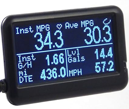
Since I decided against retrofitting the Beetle dash-pod into the dash of the bus, I still needed some engine monitoring. The old bus had 2 lights for monitoring: one to tell you you're out of oil so your engine is toasted and the other to tell you your electrical is shot. Ultimately, your warning system is your ears. Good thing the radio is so lousy, or not there, so you can hear the clamor from the engine bay. That model doesn't work for the TDI: you can't hear a coolant leak or overheating, and by the time you hear the result of the failure, it's too late. So, I extended the signal wire from the OBD-II plug from the rear of the bus to the front by the gearshift. I got a generic OBD-II plug off eBay (it's new, I just avoid Azn) that only had 3 wires: 12V power, ground and signal. The first 2 were easy, wired the 12V to a switched circuit (15) and grounded against the dash. For the signal, I traced the signal wire on the generic and determined which wire from the stock plug matched it. I know that sounds improbable, but it totally worked. Back then, there weren't the BlueTooth OBD-II readers around today. I got a wired one (UltraGauge) for around $80US that's about 1.5 inches tall and maybe 2.5 inches wide that I have jammed into the corner where the dash meets the driver-side A-pillar. I set the screen to show me engine temp and RPM's so I can watch the 2 things I care most about. I love/hate that thing. The longer I go without a coolant temperature issue, the more I realize just how much that $80 gadget saved my engine.

Along the way, I got a ScanTool OBDLink LX thinking I would integrate a more sophisticated graphical dashboard. It is pretty clever, and with a small tablet, a fuller engine monitoring capability is there for the taking. For me, it doesn't make sense until I have the fuel level and speed getting sent to the computer, so the tablet dash will wait.

Heater Fan
I had heat, but when I had my ignition fire, I removed the electrical parts to reduce the load on the circuits up front. If you intend to wire fans for heat, I suggest you find a strong source of 12V power and use an isolated circuit for it. I would just check the power draw for your fans and plan accordingly. You don't want to blow an important fuse because you kicked the fans onto high. I know I will be doing something to restore a defroster at least. I will probably source power from the battery-top fuses rather than the original bus fuse box and then use a new switch rather than the original Vanagon rear-seat heater switch. Because I already have it in-hand, I will probably re-use the Vanagon rear-seat heater unit, though. I'll just need to figure out where to locate it closer to the front of the bus without appearing in the passenger compartment.

Un-Rat-Nest Wiring
I have done this a few times and still need to do more. Unlike all of the other things on this project, this one is most like cleaning your shop or going to the dentist: you never feel like it, but you're so grateful you did afterwards. The original harnesses are not length-appropriate for this application. Along the way, we extended the ones we needed to extend. This step is about shortening all the others so you don't have a big old rat's nest of wire. I have sourced a relay block to re-route all of the relays, and I will be mounting the TDI fusebox as well as tidying up the wiring so it looks like it was all done on purpose. As of now, however, I have only removed the extra wires that were not needed.

There are quite a few wires running from the engine or computer to the front of the bus, but they can be isolated into clumps based on purpose. Accelerator pedal (6), brake pedal (2), ignition (2), OBD-II (1) and the fan switch (1)... so 12 wires. All of them are relatively thin, like 18ga or smaller, because they just send signals, and don't push power. Arguably, all of them could run through one cable of multi-colored wires (like this). If I were to start from scratch, that's probably how I would do it. In fact, I may re-do it anyway and eliminate the occasional signal loss from the accelerator pedal to ECU. If you include the speed sensor and fuel level sender, you will need more than 12 wires, so maybe something like this instead.

Prior related posts:
Preparation
Fuel System
Physical Mounting
Vacuum System
Air, Inter-cooler and Exhaust
Primary Electrical
Cooling

Next related posts:
ECU, dashpod and Sensors

Tuesday, December 19, 2017

Dashing Thoughts

Today's post is just musings about how to improve my visibility into the health / well being of the diesel engine pushing the VW bus without retrofitting a NewBeetle or MK-IV Jetta instrument panel into the spot where the current original dash lives. This is actually all related, though it may seem a little scattered. I blame the holiday season.

Speed
With a planned change in tire size, the speedometer will no longer be accurate. It's really more of a guide as it is. I know there are converter bits that can be attached to the cable to gear up and down, but I'm not really sure how well those work. There's the option of doing surgery on the speedo, like this page here suggests, but that's a little scary. Still, if I want the original speedo to show the right speed after putting larger tires on, is does read like a viable alternative.

I could figure out a means of getting the speed from a Hall-effect sender. These are basically a magnet on the rotating wheel and a magnet sensor picking up the magnetic field as it passes. This signal is effectively a square wave that an electronic speedo can interpret. OR, the computer could know how fast I'm going, if I route the signal to the ECU. But, I'd still see the old needle on the original dash, showing the wrong speed. I like the idea of being able to keep the original dash operational so I may need to do something to the original speedo no matter what I do about the ECU.

Fuel
I am currently unable to determine how much fuel is in the tank. I tried swapping out the fuel gauge when I thought I had confirmed the sender was good, but that didn't work. So, I have to consider that the fuel sender has failed. If replaced with a ALH-ranging sender, the computer would know the fuel level. But, that would also mean that the fuel gauge on the original instrument panel wouldn't work. So, maybe I could figure out a way of installing an original sensor in the tank and then splicing a second signal from that, but shift the signal in the second signal to match the modern sensor.
Original VW Bus sensor       TDI
10ohms (full)                          35ohms
75ohms (empty)                    285ohms

If the bus range is 65ohms and the TDI computer expects a 250ohm range. For each ohm change in the sender, I'd need .26 ohms of change. Plus, the floor resistance would need to be increased by 25ohms. I haven't done electrical work like this since high school, but I'm not sure how this would work. In the table below, I've split the target ohm values into 13 5ohm increments from the original bus side. The diff column represents the difference between what the sender would provide and what the TDI gauge would expect. The step increase is the additional amount of resistance needed from the more-full to less-full increment. Nothing is simple.
Bus diff step increase TDI
full 10 25 25 35
15 39.23077 14.23077 54.23077
20 53.46154 39.23077 73.46154
25 67.69231 28.46154 92.69231
30 81.92308 53.46154 111.9231
35 96.15385 42.69231 131.1538
40 110.3846 67.69231 150.3846
45 124.6154 56.92308 169.6154
50 138.8462 81.92308 188.8462
55 153.0769 71.15385 208.0769
60 167.3077 96.15385 227.3077
65 181.5385 85.38462 246.5385
70 195.7692 110.3846 265.7692
empty 75 210 285

Maybe, I could get a converter like the Fuel Gauge Wizard. These are designed to meet this problem for any gauge/sender pair which provides less resistance the fuller the tank and is empty at 500ohms or less. I could splice it in to the original wires so the stock signal is untouched while the new signal goes to the ECU.... hmm... Then, the stock gauge could still read while also informing the ECU to support the digital gauge.

Back to Dashing

If I had solved the fuel and the speed, only the turn signals would remain from the original dash that I'd need to retain. I wonder if there's a way of telling the computer that the turn signal is on....

Continuing down this mental thread, the space available for dash concepts: 13 or 14" across. 5" high. So, fitting a Jetta IV instrument panel (even if I wanted to) wouldn't fit. The one that came from the donor Beetle definitely wouldn't fit. Maybe a tablet could. A typical 7" Android is 19.2cm x 12cm -or- 7.559055" x 4.72441"

Perhaps, if oriented such that the thick "bottom" (or the far right end in the picture here) were set on the outer edges, we could support two screens for a dash.

Seeing that there really isn't an iOS comparable, I looked around for a cheap tablet. $40 gets you a bluetooth enabled, 4GB tablet (link). I couldn't use two of them without modifications to either the vent / heat controls or something else more drastic. Still, its an interesting mental exercise. Maybe it's worth only doing one, covering the blank spot where a tachometer should have been installed stock from the factory (Really VW?, Really?) and most of the speedometer, leaving the cluster with the fuel gauge, turn signals and idiot lights still visible. If the tablet can be easily removed and installed, I could pull the tablet out of the way at will, leaving the stock dash in place. I got one of these tablets just for laughs and the low price comes from the weak battery. Still, this is an interesting idea.

So, assuming the tablet isn't unattractive, how to get the engine computer to tell the tablet what's up? There are a surprising number of tools out there for this, actually. I went and bought this one from scantool. It came with free software for the tablet which I played around with a little bit.

For now, this stuff is sitting in a heap while I consider how I want to address the fuel tank level sender. Ultimately, the sender needs to be replaced, and it makes the most sense to just replace it with an original ohm-range sender. If I want to go further with the ECU stuff, I can do the fuel gauge wizard, build a hall-effect speed sensor and really jump into the electronic dash all while keeping the original functionality.

That's it for this week. Thanks, as always, for following along. With the holidays upon us, and family descending upon us, I may not have much time to post. I am taking some time off, so I'll have some time to generate content of course. I just may not get to telling the stories until some time in January. I appreciate your following, rare comments and more regular emailed thoughts and ideas. Please keep sharing.
Last, if you're in the Portland area and need a place to fix your daily, I'd be hapy to help. You can even use my driveway. Hapy Holidays and Hapy New Year-

Friday, July 8, 2011

Musical Instruments

More from last weekend... a while back I talked about adding a second OBDII plug output up at the steering wheel.  Knowing that I wouldn't have the TDI dash-pod up front at any point in the near future, I figured I needed some instrumentation.  If you haven't seen the instrumentation on an old bus, Lemme paint a picture for you.

Original Bus Dash
On one side, you have the speedometer.  Next to it is the fuel gauge and on the other side you either have an analog clock (if you own a deluxe) or a big blank spot.  The fuel gauge also is home to all the other "instruments".  First, you have the turn signals.  When you turn on the flashers or fiddle with the turn signal arm, both green arrows flash.  Neat, eh?  Yes, and only a little confusing to a first-time bus driver.  Below the green flashers are 2 "idiot" lights.  The OIL light lets you know when you're out of oil, or your engine is about to explode.  If this light flickers, you need a rebuild, but if it lights up nice and bright, your oil pressure has dropped below 3psi and you're basically hosed.  Shut off the engine, its already dead.  The other light (GEN or ALT) lets you know that your electrical system is in trouble.  Like the OIL light, a fully lit buld means you're basically hosed, electrically.  A dim light means your alternator or generator is failing to produce a full 12V (it should be more like 14V, really).  A flickering light means you have regulator issues, but a full light could mean a bad alternator or a bad regulator.  There could be other reasons too, but those are the 2 most common.

Going above Stock
Why am I going on about this?  Well, those lights won't do my any good with this TDI engine.  Many original-engine drivers add gauges for exhaust temp and oil pressure, a tach, maybe other things.  So, this isn't terribly out of character for a bus.  Rather than spend a small fortune on different monitoring gauges, I wanted to do something a little different.  First, I thought "wouldn't it be neat to be able to plug in the VAG-COM on my laptop and use that".  I've since purchased an UltraGauge, which has all kinds of meters and things on it.  Most importantly, it has the coolant temperature on the front page, which is the most important one at this point.  So, on to the extending of the OBDII...

Add a Plug
I bought a made-in-China 3-wire OBDII output plug.  The plug was poorly documented (as was mine of the install), but I'll try to cover that a little bit now.  The plug has 3 wires: red for switched B+, black for ground and blue for the signal from the ECU.  From the original OBDII plug, the brown/white wire needs to be tapped into and extended.  I had run a few extra wires from front to back, and with the interior all torn open, the tie-in (after figuring out what to do) was pretty easy.  In an earlier post, I showed a picture of an early mounting.  I've since removed it from the e-brake mount and moved it up into the stock-radio hole.  It needs to be a-fixed, but that should be relatively straightforward once I get around to it.  I need to figure out what I'll be using that hole for before I do that.

Add-on OBDII Testing
Actually testing the install turned out to be very easy.  Apply B+ to the red wire.  Plug in the UltraGauge.  Turn ignition key to run.  Wait.  It was at this point that I discovered that my engine harness efforts were not yet complete..... much to my dismay.  The P-codes returned.  I swapped Justin's borrowed engine harness in again, and the codes lingered, but it may have been because the ECU remembered them from before.  So, I figured I missed a bad wire and completed the verification of the harness, even some wires I had no reason to believe were bad.  This is where things got interesting.

Broken Harness.  New one needed
I documented every wire, and verified connectivity through them all.  I'll convert the documentation to a colored drawing later, but the important bit is every wire was confirmed.  When I put the original harness back in, not only were the codes back, but now the ECU thought my engine temp had increased from ambient (69*) to 419*.  Clearly, that wasn't right, but it was telling.  I think my efforts to diagnose the problem actually caused the problem.  Argh.  I've spent a few hours trying to find a replacement plug or harness, or some other solution, but I think in the end, I'll be needing to buy another harness at a premium - eBarf prices.  Sigh... I did mention I was flat busted in my last post, so that won't be happening soon.  Rather than cut up the borrowed harness so it can receive my oil pressure signal, I may take short flights in the bus to see if the fans come on when they should.  I figure it shouldn't take much driving to figure it out.  I'm afraid of losing my window of opportunity this summer.

That's it for today.  I still have one last chunk of effort from last weekend to talk about.  I've had the boys this past week and it's been awesome.  Lots of computer gaming and movie watching after days of heavy play involving camp and hitting the apartment complex pool.  They head to their mom's on Sunday, and I'll be returning to bus work shortly thereafter.  Thanks for following along...

Tuesday, December 14, 2010

Paneling

Brief post today. It was pouring rain this weekend, so I wasn't all that ready to work outside. So, I did some finish work on the rear cabinet (in my garage), and got the rear bumper installed when it lightened to a sprinkle. I'll have to remove it again to paint it, eventually, but Id rather have the bumper on the bus for the test drives.

Access Panel
As you can see from these pictures, I cut a small square access panel out of the bottom of the unit. Its about 4" square. When looking at the rear cabinet from the rear hatch (it would be on the left side), this hatch would be reachable through the bottom cubie. Under the hatch, I plan to have the original ignition, so I'll have a remote-starter capability.

OBDII Sensor
Those little metal squares will just hold the panel in place - as in keep it from falling into the spare tire-hole. In the picture that doesn't have my hand in it, you can make out where the OBDII port will poke in. Again, its in the bottom cubie, but on the forward wall. Once the engine is running right and the cabinet is re-installed, the OBDII connector will fit into that black housing. Since most, if not all, of the times I'll need to plug in a laptop I'll be looking at the engine, it seemed reasonable to place access near the engine. Still, we wouldn't want to disrupt the look of the cabinet, so its buried.

Otherwise, I got one of those Saab Blackstone inter-coolers off of eBarf. It looks good, arrived a little dirty, but the cooling surface looks larger than the stock one, and as you can see the input/output ports are both on the same end. I'll take some measurements and some side-by-side pictures with the stock one later on. I hear it may not rain tomorrow night or maybe Thursday. If the rumors hold true, I may get out there and start seeing how it can fit under the engine bay. If I can get a good strong fit, I can plan the air routes and get the silicone pipes on a truck before the Christmas shipping rush really kills package movement. We'll see.

Thanks for following along. Oh, it looks like the snow on Mt. Hood is getting really good. I may need to take another day at Meadows before Christmas... but then I definitely won't be test driving before NewYearsEve. Grr... the snow will have to wait :(

Wednesday, January 2, 2008

Happy New car problems

I don't know what it is about New Years and car troubles, but it seems to happen almost every year. Last year, the windshield on the bus started fogging in such a way that the defrogger no longer worked. It turned out that the old glass was seperating, and it took the turning of the calendar to really make it unusable. I think I posted on that already. If not, I'll get to it later.

I remember spending New Years Eve around 1988 in a parking garage changing a flat tire while the fireworks went off indicating the start of a new year. Yep, just the start of another round of car repairs for me, though. That year brought many car problems, and, eventually, my getting rid of that car. It was a '72 Oldsmobile Cutlass Supreme: olive on brown - probably the worst possible color combination they offered. Maybe if I'd performed the routine maintenance like oil changes and brake pads, it would have treated me better.

I spent my New Years day trying to figure out why my Jetta thinks the driver's door is open when it isn't. The dome lights stay on. The little "puddle light" stays on. That annoying "your door is open" beeping runs continuously. After spending nearly an hour with the ignition on, running the shareware version of VAG-COM into my OBD-II outlet, I couldn't figure it out. A quick trip to TDI-Club, however, showed me that this is a common failure in this kind of car. There's something about the door sensor that fails in these cars with alarming regularity. The replacement door locking mechanism costs $130. Nice for the stealers, not so nice for the owners. There's a neat hack-fix that only costs about $10 for the new switch in the door, but I'm not convinced that it lasts as long as real the replacement part, but it would take 13 of those switch replacements to cost the same as the VW part, so it makes you think.

The story doesn't end there, though. Because the puddle-light is on all the time, my battery has been slowly running down. I don't drive long distances, so the battery hasn't been getting fully charged before I turn off the engine. The hour long VAG-COM diagnostic was more than the battery would take. This morning when I went to start 'er up, I got flashing lights, lots of ticking sounds, but no start. I walked 2 miles in pouring rain to catch the bus. Happy New Year.