Showing posts with label temperature. Show all posts

Thursday, August 20, 2026

Catching Up on Cars

It has been a busy Summer of car stuff. Some wrenching, some otherwise. In today's post, I will not try to cover everything, but there has been a lot. 
 
Oliver freshly cleaned
Before I begin, you may have noticed a new sticker on the right-hand side called "Electoral-Vote". If you aren't familiar, that is a site run by 2 history professors who started a site initially, I think, to analyze polls. I have been reading their page for well over a decade; maybe 2 decades at this point. From humble beginnings that aimed to provide insights into political polls, they are a daily site that examines the (mostly) US political theater. As the national political disposition has shifted right-ward, their political position has remained around or just left of where the political middle was during the Bush years. Now, that position is left-of-center (because, again, of the national shift) in the continuum of US national politics. As the primary season has ended, they are returning to their roots, looking at polls and providing the kinds of insights only 2 life-time history and statistic's nerds could provide. If you find that stuff interesting, check them out. Neither they nor I get anything money-wise out of my putting that sticker on my blog. They get clicks, I literally get nothing. Back to cars.
 
K'Lack
P0726 re-appearing
We will start with my nemesis car: K'Lack, the 2004 Jetta TDI Wagon that previously belonged to our son K. After driving it for years and logging thousands of miles, he needed to sell it off and get something that was newer? broke down less often? I'm not really sure, but at the end he was having transmission issues. Regardless, the trade-in amount he was offered was pennies-to-dollar value. So, we bought it for Kelley Blue Book value at the time (around $4500US) and took it directly to a transmission shop who was qualified to do transmission work on these 2000's-era automatic transmissions appearing in VW's and Audi's. Through the benefits of successful aging and poor record-keeping, I don't remember how much we paid them to rebuild the transmission, but it took literally months. If I remember correctly, it went into the shop in December and we got it back in March. It was around this time that our niece (another K, so I think maybe since all these "kids" are adults now, maybe I'll just start using their names), Krista needed a car. Her former car failed in some way I don't remember. We intended to sell her Flash. Remember Flash? He was a great 2001 VW Jetta TDI sedan, but he had a manual transmission. Loved that car, but a different niece needed a car, so when Krista was unable to drive a stick, Flash went to the other niece and K'Lack went to Krista.
 
replacing K'Lack rear caliper
Now, years later, and many repairs ranging from replacing the oil pan to a timing belt and camshaft replacement, K'Lack is currently having issues I cannot track down. It is throwing a P0726 code and after tracing wires and replacing the crankshaft position sensor, the issue persists. The code means a check-engine-light is lit which means the car will not pass emissions. It is also virtually un-driveable. It barely starts and at any point during a drive the car may suddenly shift into a too-low gear, causing it to buck. It is quite alarming and dangerous. I have date with a mobile mechanic, Ian, who has helped on some of Cedar's (that's "C" in all prior posts) cars. I hope very much that we can resolve this and get Krista back on the road with K'Lack. In the meantime, it is parked under a plum tree in the back near the shop and Krista is driving Boo's (okay, her name is Angela and I'll refer to her as Ang from now on) Ang's Astra.
 
Oliver
In the interest of getting Oliver, the 1978 MGB, out of the shop so I could move things onto shelves, I got Oliver running well enough to back out and idle-drive under a tree. I say idle-drive because the throttle cable had seized. Fortunately, parts for an old MG are not nearly as expensive as parts for new cars, so a after few bucks and about 15 minutes, the throttle cable was replaced, and Oliver could start and move around. Thrilled, I drove him out to the front and gave him a long overdue bath. His brakes were still a little squishy, so I moved him to the other side of that plum tree in the back and put his cover back on. I have to do a system-wide look at the brakes. They have been acting like they needed a bleed for a long time, no matter how much I bleed them. I think I must have a loose fitting somewhere that lets air in. I still intend to get him out and around, even with squishy brakes, before the Summer is over.
  
Hapy
cursed outlet flange
Earlier this year, I got Hapy put back together. I drove him out to Sheridan where Justin could do the injection pump re-seal. On the drive home, I popped the boosted air pipe and sorta limped home. But, after that, I took him on around-town outings and he ran great. He would start right up, have lots of pep, moved through the gears well. For almost all of the month of July, he was set up festival-style in the back, providing music, a hang-out spot and a groovy vibe. This past weekend, Ang and I had 2 different events. First, we had tickets to Joe Russo's Almost Dead (JRAD) in Eugene. JRAD brings the energy of the early 1970's versions of the Grateful Dead while performing everything and anything across their song catalog. I highly recommend to my DeadHead friends. The next day, I had an early-afternoon show in Rockway Beach, playing the NCAM benefit festival. I'll post on the festival later, but our adventure started and ended Thursday night, heading south to Eugene.
 
As I've mentioned before, Ang and I like to leave for events the night before, getting as far as we can in the cool dark and then vagabonding (boon-docking to some) in a random parking lot or on the side of the road to catch a sleep before completing the journey in the morning. Hapy likes the cool air and we really like awakening that morning most, or all, of the way there. The drive was relatively uneventful until after we got south of Wilsonville. I noticed that the rear window was getting blurry, and I had just washed it when we filled up. Growing concerned, I pulled off into the Charbonneau rest area near Aurora and glided into a parking spot. I went around back, opened the rear engine hatch and could see that the coolant bottle was empty, and I could hear steam. After moving the bedding out of the way, I could get the top hatch open and could see that the coolant was escaping from the cursed coolant outlet flange. I would later discover that the c-clip or "U" clip that holds the coolant sensor in place had a broken leg (so, really a "J-clip). If you look at the picture on the right, there ought to be a little plastic tab thing sticking downward from the bottom of that dark channel on the right side of the outlet flange. That would be the end of the "U" that's not there. Our trip to Eugene was over and I called for a tow.
 
trench filled
We waited for about an hour, and the truck operator seemed fine enough. He was nice, albeit quiet. In retrospect, he seemed less comfortable with Hapy not having a parking brake but Hapy has been on a flatbed lots of times without an issue. Until this time. I believe he did not strap the wheels down as tightly as prior truck operators had. I say that because Hapy seemed to move front-to back a little bit as he backed the truck into the driveway. I had not noticed that when he was loaded onto the flat bed in the parking lot. We rolled Hapy into place, and Ang and I called it a day, returning to Hapy the next day... when we discovered that putting Hapy in gear was not enough to hold him in place. Since it was enough to hold him in place on the flatbed, at least while he was getting strapped in, and this was over an hour after we had overheated, I conclude that the tow somehow messed up the transmission-to-engine connection (read: clutch). I wanted to see if the engine was locked up, so I put a 19mm socket on the crank end-bolt and gave the engine a short turn (like 15*). The timing belt moved, the camshaft moved with it, so I concluded no major engine damage was done. Or, at least, it's not frozen in place. That's huge, but I think I will need to pull the engine and transmission apart to fix whatever went wrong in between. With this knowledge, we called it a day on Friday and spent a lovely day at the beach on Saturday.
 
trench filled
Since I still had a trench running the length of the lane-way, I spent Sunday morning filling the trench. By the end of the day, Ang and I had flat-towed Hapy back to the shop with the X-Runner and 20' of trucker's chain, parking him out front. I need to clear some space inside the shop to put him, and get him in there. Then, I have the equivalent of a clutch job ahead. The last time I had to remove, separate, re-acquaint and re-install the engine and transmission, I vowed that I would cut a rear apron into the back so I could just remove the engine. Looks like that time is now. Regardless, Hapy will probably not make it back out on the streets this summer. Could I get it done before Summer ends? Maybe, but we have lots of things going on and I don't know if I have a weekend to dedicate to that right now. Besides, if I am going to cut, I want it well planned with a means of fastening what I have removed before I pick up an angle grinder.
 
EDIT: I was trolling through some of my old posts yesterday when I came upon Front is Front which clearly describes this same coolant sensor leak recurring, until I put the clip in from below. Over 15 years later, and I'm repeating myself. Had I remembered, or read, we would not have lost coolant, broken down, etc. There's a lesson in there somewhere.
 
Wrap
With Hapy's catastrophic failure, we are down to one operable car: The Toyota X-Runner, which Ang drives to work. She has a lingering bad shoulder from a skiing crash a dozen years ago, so driving a 6-speed in rush-hour traffic is really taking a toll. If Ian and I can't get K'Lack fixed, we are going to need to re-po the Astra and have Krista solve her car need another way. Generosity reaches a limit when another's convenience is literally causing you pain.
 
Well, that's where those 3 cars are at. I have a long tale of 2 Astra's to share another time. We have lots of active construction Ang and I are doing with our friend Ray, so I'll update on that, the Astra's and whatever else happens around here as things roll. I hope the reference to the electoral vote guys doesn't cross some no-politics line for you. I generally don't bring that noise in here, but elections are coming, and we all need to be as well informed as we can be.
 
Thanks as always, for following along. Until next time-

Tuesday, February 3, 2026

Hapy Gets a FrostHeater

Today, I nearly complete the re-assembly from the flywheel (well, ring gear, really) replacement that has been an open effort since US Independence Day. I had to order a clip to hold the coolant temperature sensor in the coolant outlet flange, so this post picks up where I left off after placing that order. Before I begin, hapy belated GroundHogs Day or Imbolc, if you're a little less western in your seasonal outlook. Either way, there's 6 more weeks of winter because Spring Equinox is still 6 weeks away no matter what a Pennsylvania rodent sees. Anyway...
 
Some History 
installed
For background, Hapy was having increasing trouble starting over the past 2 years. I thought I was getting poorly manufactured starters because every time I replaced one, he would be okay to start for a few times. That was until the last couple, including a new highly-recommended starter from IDParts and a fresh local rebuild of the original TDI starter by a very reputable rebuilder. I concluded the teeth on the "ring gear" or in my case the teeth on the flywheel since this flywheel was one formed unit, had broken off enough that the starter teeth could not engage. This started a path that started with removing the engine-transaxle on my falling-into-pieces driveway, having the transaxle fall off a jack and popping off a flange, hauling Hapy in a sketchy way back to the shop, and finally, now, almost completely reassembled. When this saga completes, he would have been not running since July of 2024 (when we drove home from the final 4Peaks Music Festival).
 
FrostHeater
Frostheater is a vendor who uses a widely available Zerostart 3309040 coolant heater with hoses and brackets for a custom fit for various makes and models. If you have not tried one and are tired of cycling your glow-plugs multiple times before you can start your diesel in the winter, I suggest giving them a look. The unit Frostheater uses looks to be the top of the line from Zerostart in terms of build, capacity and cost. There are plastic other brands, and block heaters that are effectively a glue-on heating pad, but I have found these FrostHeaters to be really effective. From what I can tell, there are no moving parts. By placing the unit near the lowest point of the oil cooler loop the unit draws colder coolant from the oil cooler and the warmed coolant flows up through the upper bib into the head. That rising heated coolant then puts pressure on the coolant in the block to move into that vacuum, through the oil cooler and the loop completes. A few years ago, I installed a Frostheater into a 2004 VW Jetta Wagon (K'Lack). It worked great. We sold K'Lack to our niece a few months later, and she never used the heater. So, when we had to do a major timing belt and cam shaft maintenance, OldPoopie removed the FrostHeater, and restored the original coolant line which I left in place when I installed the Frostheater. The Frostheater and related hoses went into a box for future Hapy consideration.
 
Coolant Temperature Sensor
#6 in diagram
Before I get too far ahead of the story, I installed the coolant temperature sensor and retaining clip first. That sentence is easy to type, but the actual install is very unpleasant. In Hapy, the coolant outlet flange sits behind the fuel tank and barely above the top of the body cross-support that also contains the center-mount for the transaxle. So, there is no way to insert the clip from below, it must go in from above. Directly above the insertion point for the temperature sensor, however, is the to-the-heater side of the coolant outlet flange, leaving a 1/4" or so to fit the clip. Since the orientation of the clip is straight  up and down, there is not enough room to simply slide it in. Of course, let's not forget that you can't actually see anything because it is all on the front side of the engine. For the ALH-TDI engine install into the bay-window bus, I believe this is the single issue that challenges the install. It is minor, in the grand scheme, but it is still highly unpleasant when you need to replace this sensor.
 
So, how do we do this? With a fingernail, I find the slot on the far side (front) of the flange where the one side of the clip will go, and send one "leg" of the clip into that slot while holding the sensor firmly in place. The clip will flex hard, and the inner "leg" of the clip needs to bend somewhere while the first notch of the clip is slid in, I found that having it flex away from the flange (towards the sensor) gave me something to work with. Once the clip is most of the way down and it seems like the clip can't possibly flex any more, push the flexed inner "leg" towards the flange until it clicks into the hidden slot. I spent a couple of hours wrestling with this, and broke a clip along the way, but this method does work. These clips are inexpensive, so buy several when you need to install one. Also, I found it much easier to access the coolant flange from the driver side (the sensor side) if the charged air hose is removed.
 
FrostHeater Install
where fits FrostHeater
I could have stayed on target at this point, filled the system with coolant and started test firing the engine. In fact, I try to follow that pattern more recently: finish what you started, then do the next thing. In this case, I had already lost the coolant from just below the outlet flange and above. I figured swapping out one hose for 2 with the coolant heater was not a significant scope increase when compared to the effort to open the system to add the heater later. I figured adding it later could be years away.
 
All of the install drawings and instructions I was able to find gave very model-specific directions. I was able to determine through loosely related searches that the life of the heater is significantly extended if it does not suffer the constant vibration of being attached to the engine block. So, I looked for a place along the right side of the engine bay where it would be low enough to be nearly the lowest point relative to the engine block while still being reachable by the hoses I had on-hand. That area has a small wire bundle, the main 12V line and the diesel fuel lines, so my placement will need to be careful, but there is a section a few inches front-to-back where it could go. With that general placement decided, I shifted to hoses.
 
The BEW TDI hoses that were part of the FrostHeater kit are not an exact fit for my early ALH TDI. The top hose (red line in the drawing on the right), which runs from the top of the heater into the head hose bib which protrudes on the oil cooler side of the engine just below the coolant outlet flange (#11 in drawing), had an extra bend at the far end that I trimmed off. I felt that the extra bend made the hose want to have a large arc which would have created a hard-to-manage air pocket -or- it was a kinking risk, reducing the coolant flow. The lower hose that runs from the lower bib on the oil cooler to the lower bib on the heater simply would not work for where I could install the heater and still use the upper hose. So, I decided to reuse the hose I had originally running from the oil cooler to the head for the lower hose from oil cooler to heater (blue line in drawing).
 
viewed thru top hatch
Now, we get to hard-mounting the heater to the engine bay. The BEW install bracket on top of the heater unit was oriented to mount to the left side of something. I don't remember what. But the bracket could be easily removed with a 7/16" socket and flipped over, aligning the bracket for a right-side install. Flipping the bracket also placed the heater about an inch lower and set the angle of the bracket against the lip of the engine bay, offering some additional support. With the hoses attached, the heater unit had a smaller range of motion for deciding where to mount it without putting stress on the hoses. Still, I was able to find a spot where the bundle of wires and everything else would not get bound beneath the bracket, and marked it with a sharpie. I planned for and then drilled for a M6 rivnut. The M6 was considerably smaller than the original, but the heater is super light and I was fairly sure that bolt was designed to go into a pre-existing hole. I say "planned for" because once I got the hole drilled, there was no way I was going to be able to fit the hand-riveter into the engine bay and set the rivnut. So, instead, I simply sent the bolt through and nutted from behind like most things. It is still a M6 bolt, using washers, of course, just no fancy riv-nut. So, to remove, I will need 2 wrenches rather than one. Not a big deal.
 
Fill 'er Up
from behind approx level
With the cooling system seemingly buttoned up, it was time to add coolant and burp out the air bubbles. This is where my effort ran out of supplies: no G40 coolant on hand. I added some water to confirm there were no leaks, and after shifting the upper hose clamp on the FrostHeater, there were not any. In the picture on the right, here, you can see how well tucked up and out of the way it is, even though it is below the oil cooler. Note the dry, albeit stained, concrete floor underneath. No leaks.
 
I still need to solve for the routing of the electrical cord so it can be reached relatively easily on a cold day, but far enough out of the way that it is not subjected to flying gravel and road debris. At this point, I am looking at tucking it up behind the right rear wheel, under the battery tray and holding it in place with a strip of cable-management Velcro.It might be time to consider mud flaps back there to help protect the cable from tire kick up.
 
Last, when I removed the exhaust at the start of this project, it came apart where the pipe meets the muffler. To be honest, I was never terribly pleased with the exhaust that was put on there. But, it did last 15 years, so I can't complain too much. Still, I have a 2" exhaust kit that is a bunch of straights and turns that I intend to eventually cobble together into a better exhaust. I think, to get Hapy on the road, I will put the existing, falling apart system back in. Then, I can plan for the 2" exhaust as a near-future improvement.
 
Thanks, as always, for following along, and I intend to get coolant this week and get Hapy running next weekend.  
 

Tuesday, March 15, 2022

VW Bus Cold Air Intake

Back when Hapy was getting regular long summer drives, I noticed that the engine bay would get pretty warm. Recall back to the Newberry trip report for example. So, I put together a cold air intake concept to drop the temp going into the turbo inlet. I really do not expect to notice much of a performance difference. While I understand a cold air intake can reduce intake temps, and improve engine performance by a handful of HP, I just don't think what I did will have that kind of impact. Still, it was fun to do.

For someone running the original engine, with the engine tins and surrounding foam in place, this modification makes absolutely no sense. The tins already effectively separate the hot side of the engine from the air intake. If you have lost your tins (or foam), and for some reason cannot replace them -or- you are running a modified engine where tins cannot be fitted, something like this might work for you too to keep the hot side from meaningfully impacting your intake air temperature. This whole bit is triggering memories of that old Burger King advertisement about keeping the hot side hot and the cool side cool.
 
Before I begin, today marks the Ides of March. I am not really sure how to recommend ways to celebrate that. Pay off your debts? Enjoy a celebration picnic with revelry and drinking? Wander out of town in an animal skin? Perhaps we can all just hope Putin will suffer Caesar's fate this day for the inhumanity he is visiting upon our Ukrainian friends. Whatever transpires, in a couple days, it will be St. Patrick's Day. So, I will just get some rest to prepare for that. Hopefully, we can tip a drink within 2 meters of dear friends to celebrate a post-pandemic Spring.

Orientation Thoughts
On topic, consider the VW bay window bus engine bay from the rear hatch (picture on the right is of a '68). Most to the rear on the left is an otherwise unused battery tray. Some folks (like late-bay Westy-drivers) have a luxury battery there to power the fridge when shore-power is not available. On Hapy, there are just a lot of wires, so it's actually not much to look at. The spare tire well hangs down towards the front, meeting the rear tire well. Above to the rear there is a tall open area that eventually reaches the finned ear behind the rear window. Running along the bottom edge, front-to-rear, there is a small lip or perhaps a pinch weld that's about half an inch tall. My thought: wall this in, and create a pass-through for my engine intake, isolating it from the heat generator (engine exhaust and the turbo). Keep the cool side cool.

Parts
My go-to for all things metal fabrication these days (at least for air movement) is HVAC flashing, and this is no exception: I started with some basic 20ga HVAC flashing that I had lying around ($0). Onto the air intake, I need to add a 90* turn ($14US from siliconeintakes.com) so the air filter which used to sit next to the rear end of the spare tire well can instead go into the new cavity. The last piece is pipe flashing (like this) which cost me about $18US to provide safe passage for the aluminum pipe through the HVAC. The air cleaner needs to fit through the hole left in the basic wall when the pipe flashing is removed, so getting one large enough for this purpose was important. I had some HVAC flashing lying around, but at the time I did this, a 4 foot by 3 foot sheet (common size) would have run about $20US. A smaller sheet would cost a little less, but not much. So, all-in this would cost around $50US plus your time.

Cleanup
paper model
I learned along the way that this wall idea is not as straight-forward as it looked. As I started trying to model with a large sheet of brown paper, I realized there were some wiring clean-up items left undone. I tidied up the wiring a little bit, and strung as much as I could into the upper rear corner where the fuel vent line passes into the new cavity, securing them together (and to the vent line) with a cable/zip-tie. Below this bundle of wires, at the rear-most bottom, a couple of wires need to pass as well, so that makes 2 gaps to manage. The front-to-back T-12 cable (See the Chasing the Hapy Electrical Gremlins posts for context) routes into the engine bay where the flat rear meets the upward angle of the rear tire well, so that's a third gap to seal. Last, the stock TDI engine management cable routes into the engine bay from under the center-point of the spare tire well, so that's 4 gaps. Had I planned for this when I did the wiring, I could have potentially cut this list in half, or even reduced it to one. I preferred to not revisit the electrical again this winter, after last winter's adventure. So, I made 4 distinct gaps for wires to pass through. I numbered them in the image of the paper model on the right, here.

Model with Paper
With the wiring bundled, I could start working on the wall... with a model. I started with brown packing paper. These days, so many things ship with large sheets of brown paper as the padding, and that stuff is nice and thick, and sometimes wide enough for things like this. It is also 100% recyclable (unlike the bubble wrap), so I'm doubly a fan. Anyway, I started with a basic measurement: 22 inches deep by 16 inches tall. Of course, I discovered that the hole is not square, and the 22 inch measurement is correct from the bottom of the rear wall to the point where the engine bay curves towards the fuel tank. The top is more than 24 inches from rear to top of fuel-tank compartment. Also, the section is not flat: the bottom curves slightly inwards while the top remains straight.
 
cardboard model 1
Then Cardboard
After a few rounds of test-fit, measure/cut and some added painter tape for strength, or for adding material for sizing, I arrived at an approximate paper model. I transferred the paper model to cardboard with a pencil using some tracing and some angle-square. Consider: the rear wall makes a 90* angle with both the top and the bottom, and (I thought) the rear wall is straight. The top run is straight, though I chose to cut some of the area away which would have been pressed against the spare tire well. I made this choice for 2 reasons: first, the vacuum control valves are mounted there, and I did not want to move them. Second, having a sheet of metal against metal like that would have created rattle noise I would have to solve. With my outline and wire bundle cut-outs defined, I cut the line with a razor blade and cleaned up the edges with scissors.

test-fitting a model
With this stiffer model, I performed another few rounds of test-fit, measure/cut until the cardboard wall completely covered the gap, the wire bundles easily fit through their respective gaps and the edges of the wall were clearly in a place where I could envision mounting. The final cardboard model, in-place in the picture on the right, also eliminated a large triangular shape from the lower front corner which would otherwise have set against the driver-side wheel well. Similar to the cut out from the spare tire well, having a large metal-to-metal contact area would create a vibration-noise opportunity. Looking back, this cardboard wall looked at least as good, if not better than, the final metal wall.

Then Model with Cardboard Again
The front and bottom have a lip I can easily attach to. The top and rear will need some kind thought and some creative drilling. One additional consideration: on the rear pillar, there are grounding points which cannot be disturbed. I decided to add a small tab on either side (above and below) to hold the new wall to the rear. The top will mount directly to the spare tire well for the front 2/3rds. The rearmost section of the top, will not get any treatment at all. I thought about it, and decided that there were already enough planned fastener points to hold the wall stable without adding another hole in the cabin floor. I transferred the cardboard model to another sheet of cardboard after a few repeated fit-attempts. I want to make sure the HVAC, when cut, will fit correctly. Last, I modeled mounting tabs with scrap cardboard and more blue painters tape so I would have them in the right place and the right size when I cut the HVAC. The picture above was taken before I added the mounting tabs to the model.

Plan the Intake Pass-Thru
note imperfect rear line
With the cardboard wall in place, that side of the engine bay looked considerably better... well, it hid what looked bad, anyway. Motivated, I planned the intake route based on the placement of the new 90* aluminum intake pipe. I made a rough cut in that general area of the cardboard wall and put it back in. The 90* pipe is too long on both ends. I needed to remove about 4 inches from the end that juts into the cavity, so there would be room for the air filter (7" tall from rubber grommet to chrome top) without it touching the side of the bus. The filter housing allows for up to 2 inches of pipe before it bottoms out, so there is some wiggle room for my cut on that end. Similarly, the engine-intake end of the 90* pipe needs to be shortened. Again, the silicone collar that attaches the new pipe to the air flow meter on the end of the intake allows for a couple of inches of play. I did not make the actual cuts to the pipe at this point, though.
 
The intake looked about right, so I added in the pipe flashing. I drew the edge of the flashing on the cardboard and then drew another set of lines 3/4-inch to the interior of the tracings. I cut the smaller square out of the cardboard, making a square that was about 6-1/2 inches per side. I tested that I could pass the air filter through that hole. Otherwise, maintenance of the air filter would require removing the entire wall. It fit, but barely, leaving about a quarter of an inch on each side (the widest part of the filter is 6-inch diameter).

Adjustments
HVAC test fit
I transferred the last model above to a sheet of HVAC, but I did not fit properly and had to do another round of cardboard before I was able to get a good HVAC design. The big barrier for me was the location of the vacuum valves (so probably not an issue for anyone else). Ultimately, I removed the valves that were no longer being used (anti-shudder and EGR), and moved the turbo controller to the rear mount. This freed up the front edge of the spare tire well. The second issue will appear for everyone who tries this: I thought that the rear inner wall was perpendicular to the floor and ceiling. It is not. Consider, the contour of the rear of the bus has a slight curve; the inner skin does as well. The picture just above on the right shows the deviation from pure vertical / 90* angle. That picture also shows on the bottom rear corner that the body panels do not have clean 90* transitions either. I cut off that little tab in future efforts. With these considerations, the models were working: showing me how to get to a viable wall.
 
Assemble
prepping the wall
For the second time, I transferred my cardboard model to HVAC flashing, complete with marks for mounting tabs. I cut the HVAC with my tin-snips, and formed the wire pass-thru's with pliers. For clarity, I marked the outline of the hole and then cut crossing lines through the center of that marked area. I folded the triangular bits of HVAC back upon itself to create the opening while also avoiding a sharp edge where the wire bundles would pass. With a hammer and dolly, I smashed the fold-back flat. By doubling the material at the openings, the wall was effectively stiffened; I had not anticipated, but will definitely appreciate that. For the upper rear wire pass-thru, I left a tang or tab nearest the rear wall that I could bend back into place, so the rear edge of gap #1 (visible in the pictures of the installed cardboard model) could get covered up once the wall was in place. Once I drilled the mounting holes in the tabs I set the wall in-place, marked the holes on the bus and drilled them out.

Pipe Flashing
wall installed
At this point, I considered how I would attach the pipe flashing to the HVAC. First, I transferred the square-ish hole from the cardboard model to the HVAC, and cut it. I need to be able to remove this section so I can clean the air filter. I drilled out 4 holes in the pipe flashing, one each per side, where the rubber had dimples for that purpose. I set the pipe flashing in place and marked the HVAC. These spots were within the folded-back HVAC, making the area thick enough to tap. Sweet! So, with a M4 (.75 thread-pitch) tap, I tapped the 4 holes in the HVAC. Into these threaded holes, I sent bolts from the cold-air side with thread-lock so these bolts will act like studs for the pipe flashing. The picture above on the right shows the studs through the HVAC.

Finishing
cold air intake
I moved the wall into place and secured it to the side of the bus with sheet metal screws. I had thought about tapping the holes and using bolts instead. The holes were too hard to access with a tap and I don't think this wall will be coming out with much frequency anyway. Even so, removing some sheet metal screws is not hard. With the wall in, I re-checked my measurements for cutting the aluminum pipe. Once verified with the permanent position of the pass-thru, I cut the pipe down. I pushed the shortened 90* aluminum pipe through the rubber collar and attached the air filter. I sent the air filter into the cavity, and maneuvered the not-filter-end of the 90* pipe through a connecting silicone collar to the rest of the intake. I set the pipe flashing against the HVAC and threaded on the 4 9mm nuts.
 
When I maintain the air filter, the process will be the same as this initial install: remove 4 nuts, loosen the hose clamp and remove the cold air intake assembly. After I clean the air filter, I would re-install by fitting the flashing atop the studs, finger on the nuts, get the pipes connected and then cinch down the nuts.

final install
Now, Hapy has a cold air intake, and the left side of the engine bay is no longer a complete visual downer. Instead, we have a nice clean wall and the engine will get colder air than it used to. This wall does have some small gaps, of course, so the air will not be as cool as it could have been. Perhaps I will circle back later with something on top of the wall to better seal the edges and pass-thru's. Longer term, I may apply a thermal layer onto the engine-bay side to help reduce temperatures even more. The picture on the right, here, shows it in its current (final) state, though a keen eye will see that I had not yet plugged in the AFM (air flow meter) when I took the picture.
 
This took quite a while to actually complete, having started before the 2021 winter holidays. I had other things going on, and this was a lower priority for sure. Also, there were multiple modeling cycles as I figured out the unique puzzles added to the driver side of the engine compartment from adding a TDI (and related vacuum control valves) to the mix.

That's it for today. Thanks, as always, for following along-

Tuesday, August 24, 2021

4Peaks 2021 Road Report

With CoViD-19 impacting all facets of life, it came as a surprise to me that the fine folks who run 4Peaks were going to hold a festival this summer. In March, they set the date in August, rather than their usual mid-June. At the time, it was reasonable to assume that the vaccinations and such would make for a safe-enough festival experience. I will post all about the festival itself later. Today is just about the getting there and getting home.

Getting Outta Dodge
As you've read before, Boo and I like to leave the night before the day we intend to arrive somewhere. This is especially true when driving Hapy. Boo took departure day off from work, so while I finished up project work for our days away, she got started on our departure preparation. The night before, I had pulled everything not bolted down out of the bus, and stacked our gear in the car canopy space. This made for an easier, and much earlier departure. One thing I forgot: my toolbox. Gulp.

Unlike pretty much every other exit from home, this time we left in daylight. We filled up with B20 at our usual filling station (30+mpg again) and hit the highway. I noticed along the way that the engine missed a few times, and that continued throughout the trip. In fact, there were times when Hapy laid down some black smoke, and even threw a code. I think it was the fuel since we did not have that experience during our round-trip to Leisureland a couple of weeks earlier. I will use standard dino-diesel for this next fill-up and see if the stumbling goes away. I have not had a bad tank of fuel from Sequential before, but after that bad fuel experience in 2019, I know the symptoms. This was similar, but not nearly as bad. I mentioned the wind sheer in my post about the drive to Leisureland. The passing trucks and crosswind were more noticeable south of Portland, before reaching the OR-22. As I drove, I thought about ways to remedy.

Dash Light
It had been a few weeks since the drive to Leisureland. Recall that I discovered that the dash light for the speedometer was not functioning. Well, after a few weeks passed, and all that daylight driving... I completely forgot about it. The dash light did not resolve itself. So, about the time I passed the correctional institute on OR-22 as it started to grow dark, I turned on the headlights and, again, the dash light did not illuminate. Unlike the drive down I-5 a few weeks earlier, this time, I was driving on a windy up-down state route. So, I could not just point the bus in the right direction, and mind my speed by watching my RPM's. Instead, I just drove slower. This, I am sure, infuriated the few other cars sharing the highway with me, but I decided that getting there was more important. Besides, there are passing lanes every few miles so any inconvenience by my speed was quickly resolved.

Getting to Bend
We arrived in Bend after 10, and headed for the WinCo. After our late-night dinner at the WinCo on our way south to Eugene a couple of weeks earlier, it was just too easy. And funny. Again, the store had few fellow shoppers, and we grabbed a salad and a sandwich. We ate in the parking lot, and decided that this was where we needed to get groceries for the festival anyway, so we motored around to the rear of the store and vagabonded. We awoke before 8 the next morning and hit the WinCo for fest-food. We shared the store with a large group shopping for a camp. They literally had 20 shopping carts or more filled with food. One cart had just large flats of eggs. Fortunately, we checked out through a different line, but wow, that was something to behold.

We were still hours early for the opening gate, so we found and visited nearby Sawyer Park. We enjoyed a picnic lunch, and sat by the river for a few hours until it was entry-time. All of the pictures except the last one on this post were taken there. We followed the multiple turns to arrive at the festival grounds, surprised at how different everything looks after 2 years. We passed a new high school, through multiple new rotaries, and then the gates. We were waved through to possibly our best festival camping spot, at least since Chinook, where we had green grass underfoot and the music clearly reaching us from the stages.

From Bend to SkiBowl
4Peaks ended on Sunday without any morning events. This shortened the festival by many hours, and effectively encouraged everyone to leave earlier. Boo and I were no exception, being on the road home by 11. After the crosswind experience, we agreed that we wound try the OR-97 to OR-26 (north then west) route home instead of the usual OR-22 to I-5 (west then north). The departure from Bend was lovely, and we stopped at Quince Park in Redmond for a picnic lunch. There were a handful of young families enjoying the play structure while we used a stone picnic table. Then, we were back on the road north through Madras and on to Mt Hood.

This part of the trip was very similar to the last time we drove this way with GratefulEd in 2017 (See 4Peaks Road Report 2017) with several pull-overs to let Hapy cool down (his high temp only barely crossed 200* twice), and to let traffic pass. Unlike that trip in 2017, however, we were driving into a gusty off-center headwind that battered Hapy relentlessly. I found that I had to slow way down (under 40 mph) just so I could keep him predictably between the lines. So, our original reason for driving this route (less wind impact) was foiled.

The drive from Madras to Government Camp is 62 miles. For the first 40, it is open desert with little to buffer the wind, and only 1 lane traveling in each direction. The last third of the drive, however, is through increasingly dense forest, so the wind eased up, but the incline shifts from sporadic to constant. So, we pulled over a few times even after reaching the forest. By the time we reached Government Camp, I was ready to not be behind the wheel for a little bit. So, we stopped at SkiBowl and visited the spot where Boo and I spoke our wedding vows in the snow. It looks very different in the summer, with a stone patio and a big event tent in the area, but we used the location of the trees to guide us to the spot.

From SkiBowl Home
This last leg of our journey was the easiest. We pulled out of SkiBowl and continued west on US-26, but from Government Camp westward, it is all downhill. We pulled over in Sandy for a snack (in the bus), but otherwise drove without event. Hapy stayed cool, and there was no noticeable wind impact. We chose to avoid the interstates and took OR-212 to OR-224 into Milwaukie and then crossed the Willamette River over the Ross Island Bridge. Even crossing the bridge had less wind than the central Oregon desert had.

Ultimately, we arrived home before 6, stretching a 4 hour drive into 7. As much as I lament how hard the driving is in the wind, I will say this much: driving a bus in the wind forces you to be present like nothing else. Most folks, who are driving modern cars can afford to think about other things. No sooner do you leave somewhere then you are thinking of tomorrow or what you're going to eat for dinner or something. Not in Hapy, not in the wind, no way. You are extremely in the moment, twitching the steering wheel against the wind gusts, fighting the pitch, noting your speed, the engine temperature, the cars behind you, the cars coming at you... there is no tomorrow to think about; you need to survive this moment. So, for others, who left the festival, and were mentally in their old paths by the time they got home, I was very much in the same mental state as I was when I left the festival, albeit more tired.

Reflecting
I write all that down so that as I address the things that may be contributing to Hapy's handling, I will not forget the gift that these shortcomings provided: living in the moment... for hours. As I sit in reflection, I also recognize that this was another successful trip that did not include a flatbed towing us home. Consider too, this trip included no wrenching of any kind, no tweaks to any systems. In fact, this trip did not even include a tool box. 

As I try things to address the handling, I will post them here so others can follow. I do not intend to do anything before Hapy's birthday out of concern that he not be road-able for that. I might try adjusting his shock absorbers, but even then, I could break off a mounting stud and then he's stuck at home. As with all trips, there is a mental list of things I would like to look into, but handling needs to be first.

Thanks, as always, for following along. I will post about the festival and the music later-

Tuesday, June 2, 2020

Oil Pressure and Temperature - Final

world's most dangerous man
Before we begin, my heart aches as I watch my beloved country descending into ruin. I generally try to avoid politics in this blog, but we all eventually reach a point where we can hold our silence no longer. The absence of leadership, and the propensity for the current White House occupant to throw gas on a fire are exacerbating our national catastrophe. A disbeliever attitude towards a pandemic has gotten everyone anxious as well as over 100,000 Americans killed. Add 40 million unemployed people (many of whom are not getting their promised checks) who are going hungry and are going to get upset, looking for an outlet. Add to that what appears to be police conduct inconsistencies (white folks with guns can stop ambulances from getting to the hospital, but Black and Brown folks can't just walk down the street armed with only signs). Add an elected official directing tear gas and rubber bullets at unarmed protesters so he can have a photo-shoot outside a church after threatening our citizens with military forces. The people want leadership; we want answers. After all this, we demand, and frankly deserve, a change. Okay, back to the usual chaos oasis: car stuff.

I have been slowly working through a gauge solution for the oil system in the TDI conversion (For reference, see Oil and Temperature 1, 2, 3, 4 and 5). This really has been interesting, and I think those running a stock air-cooled motor might want to do something similar. Since the air-cooled engine runs oil hotter, the broader range gauge may work better, which means less work for you. I unfortunately did not take any pictures of the final steps setting up or installing the Porsche combination gauge. My phone died, so while it sat on the charger I readied the dashpod. Then, assembly inside the bus required 3 hands so I couldn't get a picture without risking dropping something. So, please try to use your imagination as I describe the final assembly.

Final Gauge Prep - Bulbs
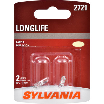
When I left off last, I had the new 250*F limit temperature innards swapped out, and that half of the gauge re-installed into the gauge. We were entering the home stretch. I focused on the bulbs next. There are 4: one each for illuminating the two gauges and one each for the 2 new idiot lights (Alt and Oil). Now, I don't have the light wired at the alternator, but I figured if I could get the gauge-end ready, it would be one fewer thing to fiddle with later. The illumination lights are simple push-and-twist 1.2W bulbs like the others in the bus dash. In fact, they are the exact same bulb. The idiot lights, however, are not like those, nor are they the same size. The alternator bulb is bigger, and the oil pressure light is an odd spade style. As luck would have it, back when I replaced the thermostat panel bulb in Flash, I had to buy a 2-pack of bulbs. That bulb (Sylvania 2721) was a match for the oil pressure bulb socket. Kismet!

Final Gauge Prep - Wiring
With the bulbs set, I shifted to the wiring. There are 4 signal wires (oil temp, oil pressure, oil warning and alt warning). For these, I simply stripped the wire ends. They already have disconnects at the gauge so I could disconnect them later when I pull the dashpod. The other wires (1 ground, 2 illumination and 2 switched 12V) needed a different treatment. In the interest of keeping the dashpod remove-able, I wired the 2 switched 12V source wires into a single male disconnect. I did the same for the 2 illumination wires. To the ground, I attached a female disconnect. Before I moved out to the bus, I fiddled with the gauge to make sure it was straight up/down.

In the Bus
warming up
The dashpod re-mounts similar to how it came out: slide it under the steering wheel from the center, near the stick shift, face down. Rotate the guts towards the hole. With the combo gauge in the third hole, this is a little harder, but not by much. Now, the hard part begins. I started with the illumination wire that was in the bus, cutting the end off that goes on the passenger-side end of the dashpod. I spliced in another wire with a female disconnect on the end as well as that original wire that I had just cut off. This gave an illumination signal that the combo gauge could plug into. Then, I started plugging in all the things that were there before... the grounds, fuel gauge, turn signals, and the low beam / hi beam and, of course, the illumination bulbs. Before I took any more steps, I tested things by turning the key to run, and flipping various switches to see the bulbs light up. Satisfied I had done no harm, I shifted to the new gauge wiring.

I started by inserting one of those "chair" disconnect splitters into one of the dashpod grounds and then connecting the ground wire from the combo-gauge. I then used my wire color map from my last post, heat-shrink splicing the gauge signal wires to the cable wires. Then, I plugged in the illumination male:female. Last, I sourced switched 12V with a covered female disconnect, and plugged in the male from the gauge. I thought about wiring it into the black switched circuit that powers the fuel gauge and the turn signals, but couldn't get my head around how to do it with one of those chair disconnect splitters without risking an accidental grounding. I wanted to minimize the wire cuts too. Last, I could have just put disconnects on the ends of the colored wires rather than splice into the original gauge wires; I just didn't. I still might.

thermostat just opening
The location of the new gauge interrupts the wire-flow for the brake warning light. I will need to extend those wires, or change the warning light location. Since we are still semi-restricted for CoViD-19, I won't be driving any great distance terribly soon, so I have time to resolve it. I found it interesting how much tension was on these wires, though; curious that there was no wiggle room on them. That was true when I went to remove the dashpod at the start of all this as well. Looking back, it was an issue when I went trying to figure out what was up with the fuel gauge years ago. In fact, removing the dashpod this time involved moving the wires one by one through the hole, while placing considerable tension on the wire, so I wouldn't mess up the wires during removal.

Unrelated, the couple of hours I spent in the bus getting the dashpod wired and installed I also test-ran the little heater with the new Afterburner thermostat. Once I had the temperature probe in a spot where it was not up against the outside wall, the thermostat held the interior temperature at a fairly static 70*F. Considering the wind and rain outside, it was really luxurious. Imagine how different the experience is compared to lying in the street gutter trying to get an alternator swapped out in front of that old Lake Oswego house.... in a late fall rainstorm. We've come a long way, Hapy.

Testing
after thermostat opened
With the wiring complete, I slid the dashpod into the hole. I found that the washers that are helping to hold the combo gauge to the dashpod will hang-up on the hole if you are not careful when you remove the dashpod. I will think about how to construct something to hold the gauge on better. Anyway, once roughed into place, the 4 Phillips screws will get it into the right position. Once locked down, I re-tested the system by flipping the key to run. The gauges lifted off of their bottom position just like they did on the kitchen table during the tests. This told me that the round-trip for the 2 circuits was good. Then, I turned on the lights and I could see the gauges illuminated. The oil warning light popped on, but the Alt light did not. This was all as I expected. Next, a test fire of the engine, and maybe a little cul-de-sac parade to get the gauges to move. First, of course, thread the speedo cable into the back of the speedometer.

Because of continued limp-mode issues, I ran my engine-running tests in my driveway. That made the picture-taking possible, though. The gauges respond as I would have expected. The oil pressure starts high when the engine is first started and then settles down once the engine is warm. The oil temp warms faster than the coolant. When I rev the engine up and down, the oil temp climbs and then settles. My last test was to check under the bus for fresh oil spots. There were none. You can see from the pictures what the coolant temperature is (number in lower left corner of UltraGauge).

With that, the oil system gauging is complete. I am not sure what's next. I have a cable for re-wiring the front-to-back stuff, and otherwise I'm just about running out of parts for projects. I do have some coolant hose and a stretch of aluminum pipe, though, so maybe I'll get after some part of the defroster. Of course, some day I'll have to get back to paint-prepping Zed, the 1979 280ZX. I'll figure it out when I get to the garage. Thanks, as always for following along--

Tuesday, May 19, 2020

Oil Pressure and Temperature (Part 5)

When I left off last time, I had a Porche combination gauge fitted to to the bus dashpod in the previously blank third-hole. I had wrangled the stock oil pressure sensor out of the oil filter housing and back into a VDO "T". Into the other side of that "T" I threaded the big dual-pole oil pressure sensor. Last, I removed a M10x1 plug near the oil pressure sensor spot and threaded in a sensor designed to capture water temperatures, topping at 150* (250*F). Today's post continues this saga with a detour into swapping out the temperature gauge innards with new guts from a new VDO gauge.

Wiring Rear
I started with the next obvious thing: wiring up the sensors in the engine bay. First was estimating where to cut the cable. I threaded it through the cable holder on the oil filter and then gave myself about a foot more. With a knife, I whittled the cable casing back to the cable holder. Then, I followed the color chart, starting with the black wire to the temperature sensor. This sensor is less than 4 inches from the cable holder, so while this was easy on the brain, it required some stretching and finger dexterity to cut, strip, attach a disconnect and heat-seal the connection. Once done, I cut the housing on the dis-connect so it could slip onto the stud on the end of the sensor. For the oil pressure related wires, I did not have ring disconnects. So, I will revisit those later, after the CoVid lockdown ends. In the meantime, I simply placed the stripped wires (red and blue for the warning light and gauge respectively) and threaded the cap down on the posts. This will work for testing purposes, but with the shaking that comes from a diesel plus the shaking of driving, one or both will fall off eventually, so I will need to apply the ring terminals.

I left the rest of the cable alone. Back when I was still suffering temperature issues, I removed the engine cover. I decided this was a great time to re-install it. So, with a couple M6 bolts and washers, the cover went back on.

More Gauge Fun
cut line on new gauge
temp gauge removed
The longer I thought about the suitability of the oil-temperature gauge in the combination cluster, the less enthusiastic I became about installing it without trying to do something about it. So, I decided I would hack-up a water temperature gauge and swap the innards with the innards of the combo gauge. My plan was for it to continue to look like the original gauge, but the top of the range would be 250*F, aligning with the sensor. This might have the opposite effect of giving me an "in the red zone" appearance when we're still down in the 230*F range. I think I can live with that, so long as the gauge gives shows a clear difference between 210*F (normal) and 235*F (my believed top end of normal).

So, how do we swap the innards? It starts with removing the temperature section from the combination gauge. It is held on with small slotted screws. Once removed, the unit pops right out. I had an extra new-old-stock (NOS), new-in-box (NIB) temperature unit I got off eBay before I got the combination gauge. I figured I would use that as my transplant target so I can revert back to the original later. I found a few differences between the original gauge innards and the new ones. I will highlight those differences as I work through this.

New VDO Gauge Destruction
old innards top
new innards bottom
At a high level, I followed the Dave Barton PDF process where you cut the housing in half to get to the inner workings of the new gauge. I found that a standard screwdriver was 1/4" thick, so I used that to mark where to cut. I threaded the collar up to that point and then traced around the gauge housing, using the collar as a guide. I taped over the gauge lens with blue painters tape and the cut the line with my hacksaw. As directed in the instructions, I cut just enough to break through and then rotate the gauge housing to extend the gap around it. The top part lifted off right where the gauge face meets the housing. Perfect instructions; nice job Mr. Barton. I also used the salad-fork method to remove the needle, using sparing force so the needle slowly lifted off the little pin. I encourage taking great care on this step.

With the needle off, I removed the small slotted screws on either side and then removed the gauge face. Then, I moved to the flip-side. With a 7mm socket, I removed the nut on the post. The tabs hold the gauge innards in by friction. So, I put the mounting collar on backwards, so I could stand the gauge on its (now missing) face, with the tabs pointing upwards. With a framing hammer, I gently encouraged the gauge innards down by tapping on the tabs and the bolt-post. If you do this take care that the pin the needle sits in does not get crushed or bent or in anyway really touched. It did not take much force to get the innards to move. I held the hammer about 4 inches from the head and tapped.

Old VDO Gauge Mount Destruction
gauge mounting plate
I started with the same process as I had done with the new VDO: salad fork on the needle. This was not as clean a process as it was with the new one. In fact, I would discourage anyone from trying to remove the needle this way if you intend to reuse the needle or the innards. In my case, the needle was damaged, and I was unable to tell how the original needle was connected to the pin. I resolved to using the new VDO needle and kept going. I removed the 2 slotted screws holding the gauge meter / face on. Underneath was a thin piece of dried up wax paper. I carefully separated that from the gauge innards.

With the gauge face torn down, I switched to the mounting side. The old gauge separates from the metal plate fairly easily. With a 7mm socket, remove the nut from the central post/bolt. With a slotted screwdriver, encourage the innards to pull away from the metal plate. It is held purely by friction.

Re-Assembly Preparation
testing old and new together
Now, we have a small pile of parts. From the new VDO innards, the tabs need to be removed from the rest of it. These simply slide out. Now, look at the 2 innards. They look very similar in some ways, but have one major difference on the not-gauge-face side. The inputs are 90* offset. If you look at the old metal mounting plate, you will see that the 4 holes around the central-post/bolt hole are 2 different sizes. The old gauge innards' holes line up with the smaller set and the new gauge innards line up with the larger set. The plastic thing that holds the tabs for the older model has 2 plastic nubs that line up with the larger holes. Those nubs hold the plastic holder and the innards stationary. If you were to cut them off, the gauge would not sit still, and could ground against the metal plate. I hadn't pieced this together when I cut them off in an attempt to get the new innards to mount. I would recommend instead that you expand the smaller set of holes so they are the same diameter as the larger set: so all 4 are the same size. Then, the plastic holder can go in in either orientation. If you hastily cut off the plastic nubs, like I did, you can solve by locating a pair on small plastic finishing tabs from one of those assemble-at-home pieces of furniture. With a little whittling, it can be formed to hold the innards in place. I suggest altering the mounting plate instead.

Re-Assembly
approximately 175*F
comparing top temp
modified on the right
However you solved for the attachment of the plastic bit to the metal plate, slide the new VDO innards onto the 2 posts. There are 2 ways the gauge innards can fit, but only one that actually works. So, when you do this, consider the orientation of the gauge so that the gauge sweep will be on the correct side. Press together firmly. Making sure the ground tab is on the bolt, thread on the 7mm nut and tighten with the socket. I considered the orientation of the new innards on the old plate and marked which side was for the signal (S) and with was for power (+) before I moved on.

If you intended to create your own gauge face, or paste on an aftermarket one, now is the time to do that. I would really like to have markings to show where important temperatures are, but I also like the simplicity of the stock gauge, so I left it alone.

To the gauge face side, I set the wax paper and then the old gauge face. I used the 2 slotted bolts from the new gauge to attach. Last, carefully press on the needle. Once it is all together, it fits back into the combination gauge housing just as easily as it was removed. If you are using the needle from the new gauge, you will need to insert a small washer between the mounting plate and the combo-gauge for each mounting bolt or the needle will hang-up on the contoured plastic near the rear (front is front) of the gauge housing. Using the 4 slotted bolts it was held on with before, mount the plate to the cluster threading each bolt through a small washer. Re-attach the wires.

Setting the Gauge Range
gauge re-installed into dashpod
As you can see from the pictures, I took the opportunity to test the new and old innards with various temperatures. First, I applied an open flame to the sensor to determine the top temperature. I then checked to see where the needles of the 2 different gauges sit when I put the sensor in boiling water. This took some doing since the "kitchen" table is 10 steps or so from kitchen-proper. I would boil some water in a small cup in the microwave and then dash over to test it. As a result, I think the picture on the above right is for around 175*F. If you consider how much gauge is left above the needle for the new innards, and that the top temp is 250*F, I will have a wide band for the temperatures we care about: 190*F to 230*F.

Well, that's an awful lot for this week. All that's left is installing it into the bus. I have to do some wire disconnects, but I don't expect it will be terribly dramatic. Now that I see the gauge in it's final form, I would absolutely recommend bus-pilots who still have their original air-cooled engine to think about installing one of these combo gauges. The original temp range is designed for the air-cooled hot oil, and it looks really good, in my humble opinion. Knowing that the new gauge innards can be swapped in eases my old concerns about long-term support as well. Just get a new VDO gauge (less than $40US today) when one of these fails, and do what I just did.

Thanks, as always for following along. Not sure what I'll work on, much less post on next. I guess I'll figure it out when I paw through my parts and incomplete projects. Stay safe and be well-