Showing posts with label 12V. Show all posts

Tuesday, May 31, 2022

Luxury Electrical Restored

As I work through the interior of the 1972 bus, I am learning that there are many layers to the electrical re-visit. I posted about the re-wire of the ceiling circuits (see Ceiling Wiring Rough-In). Today, I go over some of the other modifications I have been doing in the electrical space. I had the interior torn apart, so it seemed like a good opportunity to get after things before I put it all back together again. For example, the cushions have been removed from the rock-n-roll bed, and the cabinets have been emptied. 

Changing Tack
I am absolutely feeling time pressure, as the days get longer and camping season looms. So, I am shifting to getting things good 'nuf for Summer. What does that mean? I am setting aside the headliner. I am setting aside the carpet and the door card stuff. Instead, I am going to focus on getting Hapy operational enough for us to enjoy the Summer. The new reduced scope for the Spring includes the finish electrical (this post), completing the sound deadening (slider door and a few little bits here and there) and getting everything else that was pulled apart put back together. If I have any time opportunities pop up, I will do a little thing here or there so long as it doesn't impact our ability to take Hapy out for a spin or a camping trip.

Furnace Control Moved
Afterburner control
Recall the diesel furnace I added a couple years ago. When I did it, I added a custom computer-based thermostat, called Afterburner, hand-built by a guy in Australia. I had mounted the control unit to the side wall about where the 1979 Westfalia control panel traditionally sat. I decided that I did not need to see the thermostat all the time, and would prefer the less-cluttered look. Also, the LED panel glows whenever there is power (it doesn't have a sleep concept), so at night, it acts like a potentially unwelcome nightlight. I moved that control panel right next to that 1979 control panel: inside the rear cabinet. The wiring was readily available, and simply required another hole to be bored in the wood panel. The temperature probe, of course, needs to be in open space. I had previously routed it up along the C-pillar (between the mid-window and the rear window) and set it sort of hanging on the window frame. Obviously, that was temporary. I am not sure where I will put it now, but according to Ray, Mr. Afterburner, the sensor wire can be extended with CAT5 cable. The extension should work, but if I can avoid adding another variable, I will. Ultimately, I will solve this later. I did, however, run a CAT5 cable from the bottom of the B-pillar back to the furnace control so I could make the modification later, if I so choose.

I discovered during testing, however, that a couple of things are not working properly with the furnace. First, it test-fired okay, and it really pulled the voltage down on the luxury battery. I had forgotten about that, and the fact that I cut off the furnace wire back to the drive battery during the interior tear-out. I will need to upgrade the wiring to thicker gauge to see if that stops the heavy voltage drop, and then maybe re-plumb the wiring to the drive battery. Second, during the test run, it became obvious that the exhaust had become disconnected as exhaust started to appear inside the bus. That's bad. I will need to completely exhume the furnace and re-do the install to make sure there are no leaks. Last, there is something not right with the Afterburner controller. It no longer supports a web access point. So, it has all the other great stuff, but I can't start it remotely. In the end, the furnace will sit unused until I fix the exhaust... and the voltage drop. Maybe I'll figure out what's up with the Afterburner access point after that. Of course, it may be next spring by then.

New Fuse Box
new fuse box
I had been wrestling with a decision about the luxury fuse box for a while. I had been using a spare bay window bus fuse box. It worked well enough, but it was not perfect. It lacked a common positive post, some of the fuses had a common supply side and others did not, and there was a whole relay section that I didn't use. The fuses were the old-style fuses, not the newer bladed ones, and those old-style ones are becoming harder to source, and more expensive. Last, it is kind of big, almost 50 years old and the way I was using it was a hack that would fail. So, I bought a smaller 12-slot fuse box and a master circuit breaker / switch to put between the battery and the fuse box. Since many of the wires were being replaced, and the remaining were going to get at least touched as part of the routing, changing the fuse box was a small incremental increase in scope. I needed to remove the prior box for the noise contain efforts anyway, so I was halfway there already.

Doing the Doing
wire up in process
In the Ceiling Wiring Rough-In post, I described what color wire was going to be used for what. I ran or strung the wires to their destinations, and routed the other end down the driver-side (left) B-pillar, along the front edge of the middle window, under that window around the fridge-cabinet and left things pretty much in a heap right there. I started by completing the routing of the wires along the route that the solar collector wiring ran (See Hapy Gets Solar). I zip-tied the wires together and against the side of the bus and then solar wiring inside the fridge cabinet to hold them secure. Once I determined which fuse spots were to be used for which wire (see below), I mounted the new fuse-box onto the top of the wood box under the rock-n-roll bed which covers the old Westy rectifier.... basically in the same spot as the old one was before.

With the fuse-box in a fixed location, I could determine wire lengths and mount them up. In an ideal world, I would have used ring terminal wire-connectors on the wires. I could not find enough of them on hand, so I just used the bare wires. In classic Paulie Axiom form (See Light a Cigarette, Attract a Bus), I found them after I did this work so I will be slowly retrofitting them onto the wires. Anyway, once the wires were routed, trimmed and connected, I wrapped the bundle in one of those plastic wire tube things.

Fuse Layout
fuse wire color purpose
1 Grey Cab 12V Accessory Plug
2 Purple Cab Dome Light
3 Yellow Stereo
4 White 3-switch Dome Light
5 Pink PopTop Light / 1-switch Dome Light
6 Blue 3-position Westy Light
7 Yellow Furnace
8 Green Rock-n-Roll 12V Accessory Plug
9 Green Sleeping Area Dome Light
10 Orange Sleeping Area USB Chargers
11 OPEN OPEN
12 OPEN OPEN
 
Wait a Second...
wired up
The keen eye will notice that circuit #3 is wired up in the picture on the right, but isn't in the picture above it. Fuse #3 is the stereo. This is interesting only because of the gymnastics I executed to get it there. Before I started the noise project, the power lead for the stereo ran on the floor under the carpet. Yeah, that was not ideal, but it worked short-term. I ran a new power lead behind the dash and through the original wiring harness pass-thru hole in front of the accelerator pedal. From there, it runs along the inner edge of the passenger side frame rail and passes up under the rock-n-roll bed through what looks like a factory drain hole. A closer look at the rear edge of the wood floor will show the yellow wire running along behind / underneath. I didn't stop there, but that's another post I'll write up and post later.

Battery and Ground
Finishing up the circuit, I first confirmed that none of the wires I just hooked up to the fuse-box effectively ran to ground with the multi-meter. I returned the luxury battery to it's old location, and hooked up the ground cable to the same grounding bolt near the fridge cabinet under the seat. With the sound killer installed, it was a little harder to find.

ugly (for now) but functional
My last step was connecting the B+ or positive side. My old set up had many smaller gauge wires all wound together at the battery post. I used a very short stretch of 8 or 10ga wire to bridge from the positive post to a master switch, and then some more of it to bridge from the switch to the fuse-box. The wire was the thickest I had around. I will mind the overall amp usage, but this should not be an issue except for when the furnace first starts up. Even then, I do not expect much system stress. The master switch is a battery/fire-saver, basically, that will prevent more than 100A draw. I don't see this switch ever popping, but it is better to be safe than on fire. Based on the length of the wire, and my uncertainty about it's thickness, it is very possible that the wire will fail before the switch pops. Ultimately, I would need to have every circuit in use and have the furnace kick on to get close to even 50A. So, the switch becomes little more than a means to turn the whole system off.

Completing the Circuits
I had very little in terms of electricity consumers actually connected at this point. So, my ability to test was fairly limited and I only put fuses in the circuits as they were completed. Still, I was able to turn on the light by the front seats, and test the accessory plugs up front and by the rock-n-roll bed. All good. I checked continuity on the circuits which did not yet have a consumer, but I did not really expect any negative findings, and didn't have any. So, I started down the path of hooking up lights.

not as ugly. functional
I started with the light fixture over the sleeping area (pictured above). I used the mounting bolt for my ground, attaching a ring connector to the white wire, and leaving it inside the fixture. To the black and red wires, I connected female wire connectors. My method has been that the power-supply side wire would get a male connector, and continued that throughout. To the green (to fuse 8) and white (to the switch over the slider) supply-side wires I attached male wire connectors. I discovered, as I attempted to install the light fixture, that that 1/2" thick Mega Zorbe sound absorber was too thick for my bolts to reach the riv-nuts. I considered finding longer bolts, but concluded that the heat produced by the light fixture could have a negative impact on the foam, and chose instead to remove the foam where the fixture went. The fixture effectively recessed into the foam, which, I think will actually look better once the headliner goes in. It admittedly looks pretty trash right now. Once the fixture was mounted, I plugged in the wires, and Immediately, the red LED on the fuse-box next to fuse holder 8 lit. This told me that the circuit was good, and just needed a fuse. I popped in the fuse, and the light came on. Sweetness.

so many lighting choices
I followed this same path for the 3-position light over the window behind the driver seat (pictured above)... mounting bolt for ground, male female orientation, even plugging it all in to see the red LED. I needed to add a mounting plate behind the Mega Zorbe, but that was barely post-worthy. I cut out a small section, cut a rectangle of HVAC and screwed it to the bus. I set the fixture where I wanted it, marked and bored the holes. Easy-peasy.

I verified the pop top light at this point, and then shifted to the modified dome light (See Dome Light Mod to Trigger Other Lights). I had tried to mount this light earlier, and the mod wire broke off. I mentioned that in a comment on that original post, but I simply duplicated the effort with a thinner multi-stranded wire. On my repair version, I super glued the wire end down like before, but also added a 1-inch long stretch of superglue to adhere the insulation to the light housing. That bugger was not moving. I wrapped every bit of exposed metal (chair adapters, bits of relay, etc) with electrical tape so nothing would short out after I popped a couple of fuses. Once they were wrapped, and I could get the relay tucked in deep enough, I was able to settle the light fixture into place.

Testing the Lights
Once all of these circuits were completed, I cleaned up Hapy's interior and then hit it with the shop vac. Clean, and de-cluttered, Boo and I tested / played with the lights. The lights up front will work for checking a map or even reading a book. The original dome light, when turned on as a single creates plenty of light in the main cabin to see things on the floor, and even on top of the fridge cabinet. When the modified light circuit is turned on, the entire bus is well lit, from dash to tail gate. Since the rock-n-roll bed is not together, we could not test the reading lights for reading, but that test/play will be very soon.

With the new plan of just getting Hapy ready for the road, I do not feel the same pressure I did before. The lighting is functional, and I learned along the way that I needed to make modifications which would have been unpleasant after the headliner went in. Removing these fixtures for the headliner install will not be difficult either.

Thanks, as always, for following along-

Tuesday, May 3, 2022

Dome Light Mod to Trigger Other Lights

In my ceiling electrical rough-in post (See here), I described the ceiling wiring. Among the circuits, I mentioned the original dome light, and moving it over the slider. I wanted to take this 3-position switched light and have it optionally trigger the dome lights in the rear and the front. Today's post will cover how I made that work.

Original Dome Light
dome switch innards
Let's start with a review of the original light and switch. This switch is some basic stuff. There are 2 wire tabs near the switch and one at the other end of the housing for connecting to ground. The 2 tabs correlate to the wire that connects to the switch on the dash (if you still have it) and the switches in the doors (again, if you still have them). The door switched side of my dome light never worked, and I removed the switch from my dash so I could reuse the hole for the heater fan switch. But, I digress; there are 2 tabs. The tabs relate to either side of the 3-position switch, with the middle position for all-off.

Inside the light housing, how the switch works is more apparent. Each wiring tab has a corresponding little tang that hangs or runs down towards the lens on either side of the plastic switch. Outside of each tang runs a metal arm that connects to the positive side of the bulb. So, when the plastic switch is moved from the middle / all-off position, it pushes the little tang against the metal arm, closing the circuit. When 12V is sent to the corresponding tab, the bulb lights up.

Experimenting
So, with that context, we consider how do we tie into the switch to close a circuit elsewhere. The wiring to the other bulbs has been strung; they just need 12V sent when the switch is flipped. We cannot just attach to the metal arm, because then the remote lights would fire up regardless of which position the switch was in. If that's your goal, then that's great, and less difficult. We cannot just tie into the wiring tab because then the remote lights would be on all the time. We need to somehow tie into the movement of the switch so that when the tang is pressed outward, we can pick it up for the extra lights.

experimenting
I noticed that the little hang-down tangs are not the same length, the amount of exposed brass related to each circuit is not equal and the wiring tabs are 90* offset from each other. I do not know how much these details relate to one another, but the longer length of the one hang-down tang provide a way to tie in. The longer one is attached to the side with less exposed brass overall and with a wiring tab that is parallel with the lens. Again, not terribly relevant.

I conducted some experiments with the switch and a bare-metal female wire connector (picture on the right), as opposed to one that's wrapped with a plastic housing. I was able to set a connector fairly close to the housing, but not touching any brass, unless the switch was moved in that direction. Then, the female connector would make contact with the end of the hang-down tang. It was a great fit inside the lens, and did not prevent the circuit connecting with the metal arm. Similar experiments with a wire connector that had a plastic housing produced different results: did not work. The housing was too thick to fit in the space, even if I cut it down so there was metal exposed for the tang. I tested connectivity with a basic multi-meter to confirm that the switch would create a connection when engaged in the one position, but not at any other point.

After spending the better part of a weekend morning fiddling with this plan, I had to change it. I glued the female wire connector onto the lens and discovered that during the experiments, the connector moved slightly as I activated the switch. So, when I had it completely stationary, it jutted out just enough to prevent the tang from touching the arm: the connectivity on the multi-meter was infinite. So, that bulb would not power up had I left it that way. The lesson here, I guess, was to vice-grip the female wire connector in-place during the experiments so it would absolutely not move.

Tying In
bailing wire tang
So, I considered something that was smaller, and more like the little tang I was trying to interact with: a short stretch of bailing wire. With the tip of my needle-nose pliers, I shaped a hook-end and then a twist to create a footing I could adhere to the lens. Learning from my experimenting mistake, I set the bailing wire tang in place with vice-grips and repeated my experiments. In retrospect, something more pliable for the tang, like some thin copper or even a short stretch of solid 20ga wire probably would have been more effective because it would have more flex/give when the switch was flipped. Still, after a few cycles of set-test-reset-retest, I was able to find the spot when both the original arm and the new bit of bailing wire demonstrated connectivity with the wiring tab when the switch was in position.

I soldiered a stretch of insulated 18ga wire to the bailing wire tang, and then a-fixed the tang to the lens with superglue. Once the glue set up, I repeated my experiments to make sure that I could consistently find connectivity from the wiring tab to the end of the 18ga wire as well as the on the original light.

Triggered
Reasonably or not, I considered the amp draw through that little connection between the tang and the bailing wire, and assumed that expecting 2 lights to get powered through it is asking too much. So, to protect against overheating that connection, I'm adding a basic 4-pin relay. Recall the basics of a relay: when there is a sufficient voltage difference between pins 85 and 86, a connection is made between pins 30 and 87. So, we connect the inbound juice (that will be attached to the tab on the light) to pin 30 and ground pin 85. Pin 87 connects to the wires supporting the remote lights and pin 86 connects to the bailing wire tang I added to the light fixture. Because of where I am putting the light over the slider, there is considerable room in the ceiling for the relay and the extra wire.

Install Awaits
one switch. 3 lights
Parts of this could be installed immediately, but so much of the interior is still in disarray. The sound suppression steps are still ongoing, the remote lights are still just bare wires. I thought about stuffing the relay up into the ceiling, but decided that I could just as well wait and install the whole unit at once. Before setting it aside, I confirmed the concept, though. I pulled out a car battery, and set the 3 light fixtures on my kitchen table. I ran wiring between all the lights, and the relay, and simply played with the switches (note the fuse next on the positive side of the battery on the right edge of the picture). Yes, I did use clothespins to hold the wires together; I didn't want to stress the wires by twisting them together or waste wire connectors. When the original dome light is in one position, all 3 lights fire. When it is in the other position only that light comes on. Perfection. While I had it all set up, I played with the other (remote) lights, just cuz. I will, of course, have to retest everything when it gets installed, but seeing things light-up gives me some confidence that the concept, and maybe even the implementation, will work.

That's it for today. Thanks, as always, for following along-

Tuesday, April 12, 2022

New Cab Shelf

Back in 2016, I removed the old falling-apart sun visors that we couldn't use because they were so decrepit. In their place, I built a shelf, reusing the holes that supported the sun visors. Today's post is a revisit of that work. If you want to get grounded in the original, see Sunshade to Shelf. This version might better suit your need if you have a drop ceiling, and you are not attached to your sun-visors. 

Before I get into today's post... Boo and I hit a brand new venue in SE Portland on Sunday, 10-April (The Get Down, officially opened 8-April-2022) for Pink Talking Fish. You may recall my reference to them in the 4Peaks 2019 - Music Report where I said they were the buzz of the festival. We also caught them in February of 2020 at Mississippi Studios right before the CoViD-19 lockdown started. They have since evolved with more complicated songs, but still throwing down the funky. Translation: we danced hard. Everyone around us did too. The venue is pretty fantastic. The staff was solid, the ticket and drink prices low, and the sound mix was great. For an opening weekend, they really had it together. Boo and I highly recommend. Back to the shelf...

Why?
the original shelf installed
The original cab shelf has been such a great addition. When we were on the road or camping, that shelf was where our phones, our wallets, and pretty much anything super important goes. We would hang a privacy curtain from the edge, so it doubled as a curtain rod, sort of. In fact, if I had not gone down the path of reducing the noise in the bus, I probably would have left it alone forever.

But I did look into improving the noise in the bus. Part of that look-see including removing the wooden drop ceiling (See Noise Control Update). Once it was down, I could see that there was headroom lost to the original Westfalia interior design. With the larger Sprinter seats installed (See Hapy Seating - Part 2), that headroom was welcome. With the drop ceiling out, I figured I could move the bottom of the shelf up to where the drop ceiling was, and have sun visors again. This was a best of both worlds: I could see out the full windshield or I could flip down visors like every one else... but I would still have a shelf up top for important stuff we would like within arms' reach.

Planning
original shelf pre-install
I started with the assumption that I could take the old shelf, and shorten it a little on each side and it would work as-is. This also assumed that the cut out in the center front (front is front) that I originally made to accommodate the rear view mirror could be reshaped to fit around the metalwork that remained from the original Westy pop-top directly above the rear view mirror. This metal work supported the little tang that the old pop top would latch onto when it was lowered. Last, the old pop top scissor-lift mechanism had supporting metalwork on either side above the doors which I would need to consider.

While test-fitting after carefully trimming the old shelf to address the "tang supporting metalwork", that metalwork simply fell off. It was held in place with a single pop-rivet, installed in September of 1971, so I guess that tells us the shelf-life of a pop-rivet. Anyway, with that out of the way, I considered the need to retain the other support bits for the long-removed scissor supports. I concluded they were not needed. Similar to that front "tang-support", the side pieces popped right off. Neat. Unfortunately, all three of these support metalwork pieces left holes in the roof where the original Westy-top scissor supports used to bolt through. So, this shelf thing grew, but, to be fair, if I hadn't been looking at these support things, I wouldn't have known that the ceiling was not as sealed as it looked. In retrospect, perhaps I could have anticipated that when I removed the original top 10 years ago. The discovery of these holes led to the removal and subsequent refresh of the luggage tub (see Refresh the Luggage Tub), which I posted about last week.
 
model and shelf start
Regardless of what happened with the support metalwork and corresponding holes, the shelf, if located directly above the sun visors, may need a more complicated line. Consider that the top front of the bus is curved both front to back and from the center down to the sides. So, if I simply jammed a shelf into the space between the top and the sides, it would be shaped like an upside down spoon. Instead, this shelf will need to be lower in the center, near the mount-point for the rear-view mirror. So, it turned out that the metal tang never really was a thing to concern myself with. LOL's. The shelf ends, however, can rest on the inner lip where the top meets the sides. This will cause the shelf to cross from above to below back to above the lip that runs across the top from one side to the other.

With these constraints in mind, I started with a basic tape measure to define the line along the front. I thought I could define a point between the mirror and the side that is consistent for both passenger and driver sides. Then, I could construct a shelf that was cut to fit above the lip on the ends and secure from below in-between. The distance from lip to lip is over 47 inches and the overall drop from the center to the side is 2-1/2 inches. At this point, I abandoned the original shelf as a material.

Modeling Again
test-fitting shelf
After many measurements, I thought I was ready. I grabbed some cardboard, measured out the mid-point, end points and lip-intersection points. Similar to the original shelf, I wanted this new one to be deep enough to fit a phone, but not so deep that things could disappear. I started with a shelf drawing that was plenty deep, planning to trim down the excess once I had cut the lip intersections. The distance between the lip and the top immediately above is, like, 2 inches, but knowing that there will be noise absorbing foam and a headliner going in there, the shelf will not go all the way in. Quite the contrary, it will hang below the lip between the intersection points.
 
shelf headroom: center
I started with a cardboard model that is 48 inches wide, 3 inches deep on the ends and 5 inches deep in the center, making the rear edge (front-is-front) straight and the front edge angled (from 3 to 5 inches from edge to center respectively). The leading (rear-facing) edge of this rough model pretty much aligned with the contour of the shelf I removed and fit better than I expected. I notched front center of the model about 1-1/4 inches across, and an inch deep to fit around the center rear view mirror. This allowed the shelf to sit back, and the front lip-to-shelf intersection point could be identified on either side. I marked and cut into the model and re-tested. Again, it fit better than expected. I noted that most of the shelf would be under the front lip, with only a few inches on either end above it. This would have created a gap across the front edge, but I re-shaped that edge of the model with blue tape to extend deeper. This will eliminate the opportunity for things to slide off that edge of the shelf, and create a way to attach the shelf with small fasteners to the lip, strengthening the overall install. The overall width of the shelf could be no less than 48 inches. This left less than 1/2" on either side to rest on the lip at the edges.

Install Timing Considerations
dome light
Once I had the model defined, I had to think about the timing of this install a little bit. My plan at this point was to apply the noise absorption (Mega Zorbe) and headliner after I have the shelf in. The shelf will make it harder to get a headliner installed, but the fasteners for the shelf can be covered with headliner material. If I did the headliner stuff first, the fasteners would be visible, reducing the aesthetic. I also considered that if the shelf is in when the headliner goes in, I could integrate the headliner from the roof into the front edge (front is front) of the shelf. So, I pushed forward, with a loose plan of completing the shelf to the point of being ready to install, get the Mega Zorbe on to the ceiling and then mount the shelf.

12V Accessories
My last thoughts as I modeled this new shelf were about the placement of the 12V accessory plug and whether I could incorporate a downward-pointing light fixture. The question about the accessory plug was fairly simple: center it and put it above the shelf so we don't have cords hanging. Next! The light became complicated simply because I want a very small not-too-bright light with an integrated switch. There are many lights on the interweb, but they are mostly clumsy-large and/or very bright.
 
mirror view clearance
I chose this Europa RV dome light for a few reasons. First, it has integrated switches, rather than depend upon a door opening or a remote add-on switch to turn on and off. Next, there are independent swivel map lights so Boo can read, look at paper stuff or whatever while we drive. Last, this runs basic bulbs, not the super-white-almost-blue LED's that have become so common. Yuck. All three bulbs are a "168 wedge" style of bulb, so I could swap out to LED's for lower amp draw later... but they would have to be in the yellow end of the color spectrum for my taste. According to the manufacturer, this light only draws .7amps against 12.8V, so I'm not sure there's a great deal of improvement room with an LED swap other than longevity of the bulb. This light fixture will sit directly behind the rear view mirror, but because the central light is only 1-1/2 inches thick (swivels hang down another 1/4 inch), it will not block visibility through the mirror. I say that confidently based on the picture on the right here, showing a mirror image of the tape indicating at least 3 inches before it is entering my view through the mirror and on to the rear window. The fixture mounts with 2 screws through the housing found when you remove the dome light bezel. I tried suspending the light to the underside of the cardboard model to get a feel for how it would light the space. I will place it at the rearmost spot under the shelf to help the swivel lights reach our laps. I think, in an ideal setting, the dome light would attach to the ceiling allowing the swivel lights to illuminate our laps more from behind than in front of us. But, I like the idea of an uninterrupted headliner, so it is going on the underside of the shelf.

Materials
gap at the center
When I built that first shelf, I had free 3/8" plywood on hand from the original bus flooring. It was old, and partially rotten from 40 years of Pacific NorthWest moisture, but it was free. It served the purpose well, but I would rather use a material that is not rotted wood for its replacement. I considered steel. For strength, it is superior to wood at a thinner gauge, or course. That is, I can use 18 gauge steel and it would be as solid as the outside of the bus. It would, however, be another surface that could vibrate or reflect sound. MDF is solid, but it also reflects sound, and could chip off or swell from moisture. Ultimately, I went back to wood, well, "oriented strand board" or OSB. For about $9US, one can find a 4-foot long, 2-foot wide piece. According to reviews, this material is great for shelving because of how stiff it is, but I planned for a thin piece of wood trim for the leading (rear) edge anyway. I figure the trim will protect the edge of the OSB from chipping, and it will help hold the shelf firm in case reviews are wrong. Either way, it will help keep things from falling off the shelf into our laps, feet, whatever. I expect I will cover both the top and bottom with material; probably trunk carpet and headliner respectively, so the material choice will not be obvious once completed. In full transparency, after I made the material decision, I found a 4' by 2' piece leaning against a tree with a "free" sign on it while walking the dog. I swear, I had made the decision first. This was just dumb luck that someone a few streets over had extra material from building shelves in his/her/their garage. So, both shelf concepts have been built with free wood. Hahaha.

Shelf Build
gap at the end
I noted that the angle of the lip from ceiling towards the floor is closer to 45* than 90* to level, so the entire rear edge which is below the lip would benefit from an angled cut. Recall that the shelf will be above the lip only on the outermost few inches on either side. Whether the ends are angled or not makes no difference. 

Satisfied, I transferred the cardboard model onto the OSB, simply tracing the outline, and cut it with a jig saw. Yeah, I usually avoid power tools; call me old-skool. I have found that, with a hand tool, mistakes are much smaller, but in this case, getting the angle I just described cut correctly would have been too difficult by hand. Once that front line was cut, though, I wasn't finished. I test fit, noted where the shelf needed to have the curve adjusted and shaved some off. At this point, it became clear that a model for this was really just enough to get the shelf started. No cardboard magic on my part (YMMV) could have gotten this spot-on. It was during these cycles that I abandoned the notch for the rear-view mirror. The test-fits indicated that the shelf would not sit deep enough to require a notch.

over windscreen wall in
Satisfied with the fit, I discovered that the shelf still needed a back. I had thought that the shelf would sit high enough, or that it was thick enough, to not need something against the lip above the windscreen. The 2 pictures above show the space that needed to be filled in. To get a rough idea of the curve, I grabbed the old drop-ceiling out of the junk pile and cut the top couple of inches off the front-most edge. That got me close enough to mark up a simple arc out of some of my old door card material. The angled cut I made into the OSB worked to my advantage, creating a gentle tile to the arc that roughly mirrored the curve of the ceiling. It is not perfect, of course, but with the Mega Zorbe and a headliner, perhaps the finished product will have a reasonable aesthetic. I added 48inches of wood trim across the rear of the shelf (front is front). Then, I sanded edges of the rear wall, the point where it intersected with the shelf, the front edge and all the corners smooth. Ultimately, the shelf will wrapped in some material so the sanding may not have been 100% necessary. That wrapping, however, will wait.
 
Shelf Install Prep
test fit with 12V accessories
Finally, I was ready to finish and start test-installing this shelf. First, I added the 12V accessory plug and the dome light. I bored a hole through for the wiring for the dome light, sent the wires through and mounted the light. I moved the 12V accessory plug to the center of the shelf, rather than put it back in the same spot, adjacent to the passenger door A-pillar. I figured, having it more in the middle would make it much easier for me to use while driving alone, and it's location hides the wiring from the new dome light. 
 
I added a common grounding point directly above the rear-view mirror for the 2 12V accessories. I bored a hole through the door card material large enough for male wire connectors to pass through. To the 12V accessories, I added female wire connectors to the wire ends, expecting to put male connectors on the the colored wires I set up earlier. I verified I had plenty of the wire, but did not plug everything in. I just needed things ready-enough at this point.
 
Last, I wanted to prepare for the shelf physical mounting. During the test fittings up to this point, it was clear that the shelf was going to be much more stable than the earlier version. So, this shelf would not require mounting points other than at the ends and it was not going to wiggle-wobble as we drove around. I borrowed from the early Westfalia metal flashing I mentioned above by cutting a pair of 2-inch squares out of some scrap HVAC sheeting to fabricate little mounts for the ends of the shelf. The bits needed a little bending, a little filing, and a few holes bored through. I mounted the bits to the shelf with tiny screws, and then confirmed the fit to the bus. I marked and bored the holes into Hapy for install, but did not actually attach it. I will bring the shelf back out once the Mega Zorbe is installed. While it is out, I will attach trunk carpet, and maybe a thin layer of foam, to its top, so it is a more complete piece. I haven't decided if the rest of it will get a trunk carpet or headliner treatment. 

This is as far as I have gotten, and will get, until the Mega Zorbe is in and I have made a decision about a headliner. So, that's it for today. Thanks, as always, for following along-

Tuesday, April 5, 2022

Ceiling Wiring Rough In

With the interior of Hapy (1972 VW camperbus) pulled apart for noise control, it was a perfect opportunity to improve some of my earlier wiring decisions. Today's post covers the changes for the wiring that runs in the ceiling. There will be more posts on other parts of the electrical system later.

AWG
I think the first thing to consider when it comes to wiring, is what gauge wire to use. Most of my runs will be less than 5 meters, and very few, if any, of them will require even 10 amps. With this in mind, we consult the chart, and see that 14 gauge AWG (American Wiring Gauge) wiring would meet the need. I rounded up to 12ga and I bought a bundle. This bundle was 12 separate colored wires, each 25 feet long. Most of the wires will be feeding lamps, which draw, like, 1 amp. So, even if one run actually runs the full 25 feet, I am not terribly concerned about the wire health. In fact, I could add more lighting sources or an additional appliance (USB charger, eg) without really jeopardizing the wire health. Similar to car wiring, I set a color so I would know from looking at each end what it was for. The prior wiring had some joint bits in the middle so it might have started one color (most of the wires were red because I had a lot of it), but may have changed in the middle somewhere. That is an impossible state to trace, and I would have deserved a "DPO" label had I left things that way. With the new color scheme, I can be sure I have the right wire in hand. When combined with a fuse chart, following, fixing and effectively owning the wiring will be much easier.
 
I call out "AWG" because there are many vendors on the interwebs who will say their wire is "12 gauge", but not all gauges are alike. Their 12 gauge might be the AWG equivalent of 14 or even 16 AWG. One other consideration: copper coated aluminum wire is not the same thing as solely copper wire. Use aluminum, and/or a too-thin gauge and your vehicle will have a serious fire hazard. I encourage buying the right gauge or thicker and only use pure copper. It costs more, but the peace of mind is worth it.

What Where
I have added electrical stuff all over the place over the years in a thoroughly hap-hazard way. I considered each of them, plus I want to add some things. I have been wanting to improve the lighting for quite a while. We had the original dome light between the seat-backs, but it really doesn't provide enough light into the cab to be useful. So, it really doesn't get used. The light in the pop-top is great, and we use it fairly often when we are set up to camp. We also have the 1979 Westy 2-way light, but when I installed it, I put it where the old 1972 interior light was because it covered the hole in the wood headliner. This placed it off-center of the window which is really only an issue aesthetically. Similar to the pop-top light, it gets regular use when camping. There is no light further back into the sleeping area, and there is no light near the sliding door. With the re-wire, I intend to address all of these things.

To replace/improve the cab lighting, I will install a new dome light closer to the front of the cab. To create some lighting in the sleeping area, I will install a switchable light fixture on the rear ceiling. This light will also double as a light-source for the engine bay. Last, the 1979 Westy 2-way light will move a little further forward for aesthetics. In it's old location, it cast a shadow in front of the fridge cabinet. In the new location, the floor in front of that cabinet will be well-lit, without losing lighting into the fridge cabinet.

Last, the original dome light is getting moved to the ceiling near the front of the sliding door. So, when you open the slider, there is a low-intensity light we can flip on. This will help us getting in/out of the bus when it's super dark out. This switch has 2 positions (I'm calling them switch 1 and 2) originally designed so you could switch it from door operated to off to manually operated and back. In my implementation, switch 1 will turn on the original dome light as well as the dome lights I have mounted in the cab and in the sleeping area. No, the switch was not originally designed to do this, so I am modifying it. I'll post on that later. Switch 2 will only turn on the light by the slider. I thought there would be times when lighting up the entire bus from one switch might be useful.

The circuits, or should I say 12V consumers, I am considering from front to rear. I'm using letters so I don't pre-dispose myself on fuse numbering:
wire hole from above
a -* (grey) cab 12V accessory plug
b -* (purple) new cab dome light
c -  stereo <- will probably leave as-is or run under the floor
d -  amplifier for stereo - not wired yet, would probably follow stereo wire
e -* (white) original dome light switch 1
f -* (pink) original dome light switch 2<- will share pop-top light wire
g -* (pink) pop-top light
h -* (blue) 2-stage westy light
i -  furnace
j -  12V accessory plug by slider door
k -* (green) sleeping area dome light
l -* (orange) sleeping area USB charger ports - to be figured out

*: ceiling wired (wire color)
 
In the past, I had 3 wires running through the ceiling, but it was a total hack. I sent the wire bundle inside the Baltic Birch drop ceiling to the rear driver corner where it basically just dropped down along the inner wall, behind the rear-most window to the floor. From there, it ran forward to the fuse box under the rock-n-roll bed. This worked, but it looked pretty bad and the wires ran probably 5 meters longer than a direct path would take. And, I would catch the wires when loading/unloading gear. With the drop ceiling removed, I could see where the original VW/Westfalia wiring had been run along the top edge where the side wall meets the ceiling and it led me to my improved solution.

Implementing
original dome-light mount

The rear side of the B-pillar (directly behind the front doors) is hollow. In the top edge where stock wiring runs, there is a factory hole from the edge into the B-pillar. This is probably intended to route a sunroof drain or something. I used it to route the wires from the ceiling down along the front edge of the middle window and into the dead space under the window usually hidden by a door/body card. From there, the wire bundle runs rearward and around the old fridge cabinet to the fuse-box under the rock-n-roll bed. This path is considerably shorter, which reduces the opportunity for a wire to short as well as reduces the drop in amperage between the battery and the appliance simply because a shorter wire experiences less loss. I ran the wires one at a time, from below upward. I threaded the first wire by chasing bailing wire down from above first. To that wire, I duct-taped my first wire. Once it passed through the hole, I duct-taped the next wire to the first, and sent it up and through. I repeated versions of this until all 7 wires had passed through. I am not sure there is still room for another wire, if I need to send another, like, for the ambient temperature sensor for the furnace thermostat.

One point worth highlighting: all of the wires are intended to serve a single consumer except the dome lights. The pink wire will support the pop-top light and the original dome light when only that light is turned on, which has moved above the slider. I moved it because the most frequent need for light is when we enter that door, so having a switched light right there will be very useful. Why share? Neither light will draw much, and even if they are both on at the same time, the draw will be well below the limit for the size wire. The same goes for the other position (white wire), since those dome lights draw so little. Besides, that B-pillar pass-thru hole was getting crowded and the number of isolated wires is probably already overkill. When I think of how many fuses there are for the entire electrical system for Oliver (1978 MGB), this plan really feels like over kill.

At this point, I have not yet tied the wiring into the fuse box. Since I will be addressing the fuse box, luxury battery and, maybe, the old fridge circuitry later on, simply having the wires snaked from their termination points was sufficient. Let's call this the "electrical rough-in".

Well, that's it for today. This took me an entire weekend day just to get this far, though I also removed all of the old luxury wiring and that takes a little time too. I accept that I move slow and quality... well, snaking wires... takes time. Thanks, as always, for following along-

Tuesday, August 13, 2019

Making Hapy Sounds (Part 3)

continuing from the Part 2 post about getting music into Hapy the wonderbus. When we left off, we had front speakers installed and rear speakers floating around in their own little speakerboxes. The wiring for all speakers had been routed back behind the dash. For the front speakers, the work was mostly a finished product. The rear speakers, though, were still very much in an experimental phase. Today, we wire up the head unit and complete the work.

Head Unit Physical Mounting
You know how when you swap out a big car stereo (a double-din) for a smaller one (single-din) you usually install one of those plastic boxes in the extra hole? Well, I had one of those box/bin things in my garage, and it had been there for a few years. So, I figured I'd put it to use. Shortly before we left for 4Peaks, I stuffed it into the radio hole in Hapy. On the drive and while at 4Peaks, we loved the extra storage spot. On the drive, it was where we put our phones. While we slept, we put valuables there. So, I didn't want to remove it to put in a stereo. Honestly, it was jammed in there so hard, I'm not sure I could get it out without destroying it anyway. AND, there was nothing in that are to physically attach a stereo to anyway. The old DarkStar stereo was held on from the front. Modern stereos need something to attach a rectangular channel to, and there was nothing there in the bus to bolt it to. So, I popped it into the glovebox instead. It still needs a real mounting, but for version 1, it sits on top of the packing cardboard it shipped in. Will it bounce around? Maybe. Could I break the stereo because I didn't mount it properly? Absolutely. Blindly moving forward, I drilled a 3/4" hole into the driver-side of the box, near the back, to run wires. With the glove box closed, it looks like the bus doesn't have a stereo... like it hasn't for the 15 years I've owned it.

Head Unit Wiring
In retrospect, I could have started here. I am not going to Should on myself (see Don't Should on Yourself), but if I ever have a virgin stereo install to do again, I will. Consider: the 2 most important bits for a stereo install to be successful is for a solid ground and a reliable source of 12V power. One could just solve those 2 wires and confirm the stereo works and your power is good before you do anything else. Wise advice for a future me. Anyway, for a ground, I doubled-up on a o-ring-d ground that was screwed into the air vent box. I verified that ground was good with a continuity test back to the negative post on the battery. For power, I tapped into an always-on circuit but it did not have enough juice to power the stereo. The radio acted like it didn't have any power, though I could read 12V at the plug. So... let me back up and then I'll get back to this.

I wired ground first. Always do ground first. Then, I took the various speaker wires and mated them with their respective colored wires coming out of the stereo plug. I intend to swap these into something more like the plug in Oliver, but this is fine for version one. Last, I tapped into a 12V source, hiding the wire, etc. Then we test fire.... nothing. This is where ideally I would have run ground, and 12V to prove it will power up before doing anything else.

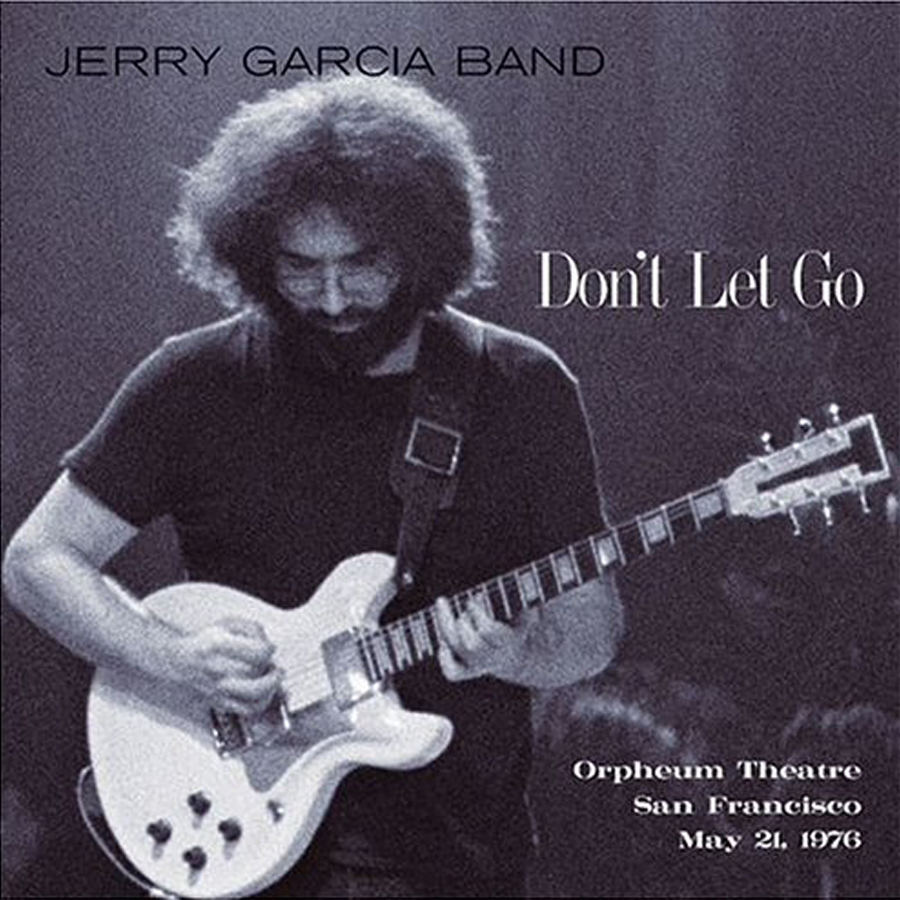
https://jerrygarcia.com/album/dont-let-go/
By now, it was getting late and I was getting tired and hungry. So, I ran a hot-lead from the luxury battery (our name for the deep cycle battery under the rock-n-roll bed that powers the lights and 12V sockets) to the back of the head unit strung across the lot couch, with a big coil bouncing between the front seats. It looked super-janky, but I needed to test whether the stereo would power up, and whether the speakers would respond. I plugged it in and heard the CD whir, so I knew I had power. So, I grabbed Boo and our copy of JGB's Don't Let Go CD for a test-listen before we both called it a day.

The smile produced by a JGB "Sugaree" is virtually a given, especially from the mid-70's era. That smile was compounded by hearing it coming from all around us in Hapy. "How loud does it get," Boo asked. She remembers our struggles to hear on the road as acutely as I do. Turning it louder and louder... it never distorted. Pure Jerry deliciousness pouring out of the speakers, hugging us with music until we were unable to talk over it. Yeah, that'll do.

12V Source Fixed
We shut things down, and I cleaned up my mess for the night. The following morning, I was back out there to run a 12V lead from the luxury fusebox to the stereo. This sounds simple, but it took quite some doing. I started at the glovebox, running a stiff 12ga wire through the hole and down behind the front "floor" vent. It runs below the TDI accelerator pedal (See Pedal on the Right) and under the rubber floor mat to the right edge of the driver seat pedestal. It runs along the right edge of that pedestal and under the old seat mounts for the 1972 Westy rear-facing seat, under slides for the lot-couch / middle-row seat and under the front edge of the rock-n-roll bed cabinet. It appears behind the cabinet near the corner by the refer-storage cabinet. I wired it into "fuse #12", protected with a 16amp fuse. I layered tape on top of the wire where it intersected with the lot couch slides to we don't accidentally catch that wire when putting the couch back in. That would be bad.

Once I had the new 12V supply line set, I re-tested. All good. I took the opportunity to tuck away some other errant wires up front. That's it for today. Version one is ready for some test drives and a festival or camping trip before we make any modifications or harden wiring to the rear. Thanks, as always, for following along-

Wednesday, June 3, 2015

Putting it to Bed

By now, most of the hard parts had been completed. Today's post covers the final bits and pieces, putting the project to bed, so to speak.

Rock 'n' Roll
bed, before
With the bare floor painted grey, the first of the last phase was getting the rock 'n' roll bed in. I'd pulled the contents out prior to its removal, but the bed is still pretty hard to move around by yourself. Still, with a mixture of dragging and heaving, I got the bed up and into place... without making the floor look too shabby in the process. Since the floor no longer had wood sheeting on top of it, getting the bed to align with the holes on the top of the engine bay wasn't quite as easy. It found it's home, though, and I was even able to get the little 2-bolt bit from the passenger tire well to slide home.

In the Light
Under the bed fits the auxiliary fuse box and battery. While in previous incarnations of this set up the battery powered a few different things, all it powers now are lights and 12V adapters. I already touched on some of this effort in an earlier post (see bump bump bump under "Cabin Lights"). Once locked in, I could move on to the refer cabinet.

bed, after
The Crunge
The fridge cabinet had previously just floated around, but I hadn't known that until removal day. Between removing the rear closet and the stove/sink, it held in place through simple inertia. There is supposed to be a bolt that threads into the fridge from the bed. That's now back in place and the cabinet is locked in tight. Between the fusebox and getting this cabinet in place, there were some wire-management issues too, but they're all well routed now, so no furniture is sitting on top of a wire. I still need to get the shore-power capable of charging the battery or simply feeding the lights and such, but that's something for another day.

Kashmir
middle seat in
We're getting near the end. I put in the rails for the middle row seat, following the holes and some blurry photos I took from the prior install. Without the wood floor in place, it seemed like the rails synch down tighter, but really, they were just lower, making the placement of the seat in the rails a little harder. After first just setting the rails in and finding that they were too close together for an easy fit, I took another tack. With the bolts in finger-tight, I tapped the rails as far apart as I could make them. Then, tightened them down for a fit. The seat slides in as easily as it used to (which isn't all that easy). I may need to Lithium grease the rails so the seat goes on easier.

In the middle picture, you can see that I've covered the rear driver-side window. I posted in "Whatcha Hiding?" about the screens I made a few screens to cover that window. As a final preparation, I painted the side that faces the inside of the bus with the same grey paint.

Well, that's really it for getting the bus back together. I was able to get it all done before the Memorial Day weekend so I'll post on that next time.

Thursday, January 22, 2015

Early Bay Windshield Washer mod (part 3)

Continuing from the last 2 posts, this part of the washer modification focuses on the electrical. Sorry it took so long to get this out. I ran into challenges getting the switch installed, as you'll see. It does work, and I've already moved on to the next big thing... which I'll get to posting about soon, I hope :)

Pump Wiring
The pump has 2 pins. I can't speak for the vanagon pump, but the more modern pump I used doesn't appear to be polarity sensitive. Meaning, you can apply 12V to either pin, with the other to negative/ground, and the pump will run the same way. Neat. I wired the pin closer to the rounded end of the plug to ground. For a ground, I used the headlamp ground, and an insulated ring connector on the end of a brown wire (brown for standard ground color consistency).
The signal or 12V pin was wired to the wiper switch with a green wire. The other pin on the switch was red-wired to the number 30 terminal on the wiper switch. I mentally debated this point. I could have used another circuit in the fuse box, but finally concluded that having a single fuse/circuit dedicated to the wiper and washer should be fine load-wise and easier to diagnose later.
I tested every connection with a multi-meter, verifying that continuity existed before moving on to the next section. I also applied 12V at the terminal 30 and demonstrated that the pump would fire when the button was pushed before considering the electrical done. I still had the switch to install into the dash, but the system was otherwise complete... but, of course, getting the button into the dash is what started this multi-post topic.

Prepare the Switch
roughed-in mount
(pre-trimmed)
Arguably, this is getting into what you have most likely been waiting for. The old switch/valve needs to be taken apart. The valve is held on with 2 long brass rivets. Drill them out with a 9/64 drill bit. A slightly larger one might work too. Once the rivets are gone, the valve pops off. Grab the small rubber disk that sits between the button-rod and the valve; you'll need that disk later. In my case, when I separated the valve from the switch, the rubber disk didn't just sit there, it jumped and ran. Chase it, you'll need it. Push the long brass rivet remains out of the switch.

Fab a Mount
With a pair of tin snips, cut a 3/4" wide strip from some grade 24 ducting. Step-drill a 1/4" hole in the center. Bend the strip into the shape in the picture here, and then drill 7/64" holes center-aligned with the larger 1/4" hole. To prevent the strip from grounding against the tabs on the switch, it needs to be trimmed down with the tin snips. This takes a few rounds of test fit, trim, etc. File the sharp edges. Your fingers and wiring behind the dash will thank you. 

Put it Together
switch during testing
Once the mount is formed, slip the McMaster-Carr switch through the hole, include the washer and tighten the nut. With 2 #8 Phillips-head screws (not bolts) each at least a 1/2" long, mate the mount with the switch. Test the fit with the knob and button (with long pin) in place. I found that the button on the McMaster-Carr switch and the end of the long pin didn't exactly meet, so some fiddling with the mount was necessary before it could be fully torqued down. We now have a working switch. But when bench tested, the pin without the rubber disk doesn't hit the McMaster-Carr button cleanly 100% of the time. So, the rubber disk needs to be part of the final equation. You can see the disk in the "testing" picture. This is where it gets interesting.

Dash Install
The old wiper switch fits into the dash by being fed through from the front (front-is-front!). The new switch with the added washer activator does too, but there's a complication. In order to fit through, the knob and button with the long pin need to be removed from the switch. If the long pin needs to have the rubber disk set onto it to properly activate the McMaster-Carr button, then how do we assemble all the pieces? It's not easy. I tried spot-gluing the rubber disk to the end of the McMaster-Carr switch. No good. I tried removing the mount, installing the switch into the dash and then re-assembling in situ. Nope. I tried a few other permutations too. I was able to get the whole thing installed and functional by barely threading the McMaster-Carr switch into the mount, and installing the dash-switch into the dash hole like that.... with the dashpod removed so I could get my hands in there. Then, install the turny-knob (beware: technical wibble-ly wobble-ly terms ahead) onto the dash-switch. Next, hold the rubber disk against the dash-switch while feeding the button with the long pin through the turny-knob and press it into the tiny hole in the rubber disk. This is hard with thicker fingers. Now, tighten the nut around the McMaster-Carr switch to set it tight. Test the action with a multi-meter to make sure the switch activates properly. If necessary, the mount can be pressed tighter towards the dash for a reliable action. After all the fiddling, mine needs a slight adjustment.

Button It Up
Once in-place, test the washer system first without water. If the pump fires up when you push the button on the dash, you can then test with water in the bottle. It will take a little time for the pump to prime, and for the washer lines to fill. Once the water makes it to the nozzles, adjust them so the stream lands in the center of each wiper path. Once adjusted, verify the tightness of the various mechanical connections (pump to body, switch to dash, etc), put your kick panels back on, and you're done! Hazah!

That's it for today. Thanks, as always, for following along. I hope you found this useful. More next time...