Showing posts with label alternator. Show all posts

Friday, May 29, 2026

Moving Into Shop

It has been a busy couple of weeks spent mostly moving stuff from the tool shed into a big heap at the front of the shop. I did get to wrench on Boo's car, Astra, though. Today's post is mostly about Astra, but the pictures show the move of stuff as I didn't get my phone out to take pictures of Astra's alternator replacement.
 
Weather the Weather
shop heap
One of the best parts about living in the Pacific Northwest are these incredible spring days. When I first moved here decades ago, we would enjoy what I called "the weather donut hole" in April. It was a short, maybe 2 week period, when the rains stopped and we got these just gorgeous sunny days. Then, we would descend into another 2-1/2 months of rain until July 5th. Through the wonder of climate change, our spring weather donut hole has grown. Maybe 10 years ago, it would last most of April. As recently as 2 years ago, the donut hole never closed, and we did not get much more than 2 or 3 days of rain a few times before the summer dry season hit. This year is looking more like 2 years ago did, with mostly clear and dry days with a few passing rains to knock the pollen out of the air. While I worry about summer fire season, we make the most of these below 25*C (80*F) sunny days with daylight lasting until 9PM.
 
So, with that backdrop, I had a meaningful car repair to get after.
 
Astra's Backstory
Boo replacing Dude's starter
Well before I met her, Boo used to drive an Opel Kadett. Always generous, she let some friend use it and never saw it again. Years later, when I met her, she was driving a gold Saturn sedan (named "Dude"). She loved that car, doing everything she could to keep it on the road. Again, a friend of my dad needed a car for a while. This friend was running errands for the less-physically able in my parent's building, so she loaned him Dude. It was stolen, and when it was recovered by the police, the ignition and steering column were destroyed. With considerable sadness, she let the car go to police impound auction. She had owned Dude for 18 years.
 
Fast forward a few years and I'm driving along and find myself behind a 4 door hatchback with a Saturn symbol on it. At the next red light, I snapped a picture of it and sent it to her. We were in the market for a new car after the GoRo disaster and had been talking about a Mazda3 or maybe a small SUV. The Saturn appeared to be an intersection of her appreciation of the looks, lines, mileage and size of the Mazda3 with her love for Saturn. I started investigating and learned that the Astra was built with Stellantis/Vauxhall, owner of Opel and original manufacturer of the Kadett. In fact, the Kadett evolved into the Astra. So, the Astra was really an intersection of her beloved Saturn, her equally beloved Opel Kadett and her appreciation of the Mazda3. Of course, now I had to find one. The Saturn Astra was only available in the states for 2 years (2008 and 2009), and not many were sold. We lucked into one outside Salem for literally $2kUS and after applying another $1k of repairs and tires, it has been a fantastic family member.
 
tool shed "empty"
She is not without her issues, though. Sometimes she does not want to downshift and just groans in a too-high gear. This is reset with a restart, but that's not easy in traffic. Over the last 18 months, though, the battery had been not charging enough on shorter drives to start again. She priced having someone replace the alternator, after having it checked, and the $800 price tag lead us instead to get a jump pack to jump start her when she didn't want to start on her own. This lasted over a year until a couple of weeks ago I took on the task of replacing the alternator. By the time I got to step 3 or 4 in reading the online "how to", I understood why shops were giving her a "go away" price.
 
Alternating Astra
In January, Boo and I planned for a trip to the east coast the week before Memorial Day. We were going to visit my sister and her family and then see our son K2 (currently serving in the US Navy at Quantico). Then the trump administration decided to pick a war with Iran, airline prices spiked and our plan was scrapped. Thanks trump. Nature hates a vacuum, so what would have been a trip to the east coast became an opportunity for me to spend up to a week fixing her car with no drive-to-work pressure.
 
shelving starts
The challenge with removing and re-installing an alternator on the Astra is that the alternator only fits out the left front (passenger-side) tire well. Even then, it doesn't fit easily. So, the process is you get the car up on a jack, remove the wheel and the inner wheel well just so you can approach the serpentine belt and alternator. Disconnect the battery. I put the battery onto a charger while I did the rest of the job. I found removing tension on the belt tensioner especially difficult because of the required body positioning to access it and the steel supports blocking direct access. I used a spanner-on-a-spanner (yes, it's cringe-y) for sufficient leverage. If you reuse the belt, mark the belt direction. With the belt off, you can get at the 2 alternator bolts. With the alternator loose, reach around the rear and unplug the 2-pin socket. It has a latch holding it on. I palmed a small bladed screwdriver around everything and got the latch to release without breaking it. Then, remove the nut holding the main cable to the rear of the alternator. At this point, some folks have posted that they have been able to worm the alternator through the wheelwell. They must have a different engine than we do (2.0L). I needed to remove the air box and then the engine mount bolts underneath it, so the engine on the left side was no longer attached. I did set up the TravisJack under the engine so it didn't lower at all. Then, the engine itself needs to move as far forward as you can manage it. I just grabbed onto it from over the radiator and pulled. The alternator drops down and out behind the engine and out the rearward end of the wheelwell opening. I found that if the alternator is in the same orientation as it was when installed, it does come right out. Any other orientation and it will get stuck. Yes, this happened to me many times until I figured it out.
 
end of day 1
With the old alternator out, the install is mostly the reverse. Alternator enters the wheelwell oriented as it will be installed. I plugged in the socket and nutted on the thick cable before then attaching the alternator to the engine. Next, I put the serpentine belt back on. It has maybe 20k miles on it since it was replaced by the yard we bought the car from. With the belt tension restored, I moved the engine back into place and re-connected the mount. Then, I put the airbox back in and returned under the car to put the inner wheel well back on. I finished up with putting the wheel back on and the battery back in.
 
I had read online that this was a 8+ hour job, so I had set aside 2 days, hoping that I'd be done by Sunday in time to see our friend Maldarine play a show. It took me 6 hours, start to finish, backing her out of the shop and the lane way back into the front well before dark on Saturday. 
 
Moving In
With all the extra time I now had, I decided that I would get as much of our summer project done as I possibly could. I figured that it wasn't raining and every nice summer day I could save by doing things now, would make for a better summer. This year's project is getting everything car-related into the shop and everything home-repair related into the tiny shop (tool shed). Then, the only stuff in the garage is camping and ski gear, leaving plenty of room for Boo to park Astra when the fall rains return.
 
partway day 2
I had started with the garage, moving the red rolling tool cabinet before I even had the doors installed. This renewed effort was about getting anything else car or tool-related from the garage into the shop. This included my jacks and stands, the hypersonic-cleaner and lots of random parts. All that remains is my big black rolling tool cabinet. I hope to move that this week.
 
Next, was the tool shed. I regret not taking a genuine before picture. The shed was so full, the back half was out of reach, blocked by stuff. So, those large items blocking the floor were first, rooting through them a little bit looking for junk before moving the keeper-bits to the front of the shop floor. I noted that there was evidence of rodents, so I spent the next few days wearing a dust mask, shop-vacuuming a lot, and generally moving at a slower-than-hoped pace. I would vacate a shelving unit, dismantle and wash it, move it, and finally re-assemble it inside the rear of the shop. Most of the stuff that were on the shelves ended up in a heap at the front of the shop, or a heap for the dump. The exceptions to this were solvents and cleaners, which went onto freshly cleaned shelving, and everything painting related, which went into an old kitchen upper cabinet the kids used to use for skate and snow gear repairs and parts.
 
Those with a keen eye will see (in the shed heap picture at the top) that I put Zed on furniture dollies so I could move him around a little bit. These dollies are the $30, 1000# max variety found at Harbor Freight. The genuine car dollies I've seen cost up to 10x that much. Are they 10x better? Unlikely, except they work on heavier cars. I was able to move Zed by myself, one end at a time, so I could fit a shelving unit against the wall beside him. I used another pair of those same dollies under the paint cabinet.
 
paint cabinet on wheels
Boo and I agreed that the Tetris I did to get Zed's entire interior onto the high shelf in the tool shed could not be easily repeated (see the upper deck in the tool shed "empty" picture above), so that stuff stayed. Otherwise, the tool shed is clear of car stuff, the shed is cleared of all evidence of rodents and the shop vac has been emptied and washed. Next, I will be moving home-repair stuff from the garage.
 
Wrap Up
This got really long, but a lot gets done on a full week stay-cation. I hope to get after the big black rollie cabinet and the garage-to-tool-shed over the next couple of weeks. Then, our summer project will have been completed before summer even arrives. We all know nature hates a vacuum, so that time will be filled by something. And that something will probably be either home improvement or car-related. Once that happens, I'm sure I'll post about it. Until next time, thanks, as always for following along-

Tuesday, February 2, 2021

P0121 - the 1200 rpm limp mode - Final

Today I complete the saga of trying to resolve the P0121 error that persisted after I re-wired the front-to-back cable, the fuse box (main donor) harness and the fuse box / relay box. It is terribly ironic that this post arrives on Groundhogs Day. I have had drive-by-wire (P0121) issues so much since I did this conversion, it was like my own personal Groundhogs Day every time I dropped into that 1200 rpm zone. Queue the Sonny and Cher song. With only one error code, you would think this would have been easy. Nope. At least, after all the wiring changes, I only had the one code.

Pedal Pedal
new on bottom
When I left off my last post, I had concluded that the wiring was not the issue, and ordered a replacement pedal. These aren't cheap, but I found one for around $100US (which was a really good price). It took a while to get here from the east coast, but once in-hand, I thought it would be interesting to compare the new and the old. Physically, they are very similar, but the old one has a removable panel. I pulled out the multi-meter and started testing the resistance between all of the pins on both pedals. This was illuminating.

Then, I popped each pedal into a bench vice so I could depress the pedal by tightening the vice. This allowed me to measure how the resistance changed across the pins as the pedal was depressed. Generally, both pedals demonstrated the same direction of resistance change relative to the direction of the pedal movement, but there were some definite differences. For example, the resting resistance between the pins (which had a corresponding resistance on the other pedal) was lower on the old pedal than the new one. I was able to correct for most of the difference by shifting the little cover on the old pedal forward (front-is-front / away from the footpad). Prior to moving the cover, it was near the mid-point of the front-to-back adjustability.

The biggest difference I found was that on the new pedal, there was infinite resistance between pins 2 and 4 when the pedal was 0% depressed. The old pedal, however, had a measurable resistance (1760 on the second-to-highest sensitivity). Once the new pedal moved even a little off of 0% depressed, resistance was measurable. I thought this was the big tell that the old pedal was the cause, but before I get into the in-situ test, here are some tables and notes around my testing of the 2 pedals. I suspect there will be readers who are only here for that.

Testing Static Resistance between Pins 
inside the removable
cover
In the table below, the multi-meter was set at the second-to-most sensitive resistance measuring. The number on the top is from the new pedal, and the number below it is from the old one before I tweaked the little cover position. 

The word "flash" means that even though I tested these pin resistances 5 or 6 times, on the new pedal, the resistance between these pins would flash a quick 4-digit number and then go to infinity. I tried to measure it with different settings on the multi-meter, but for my purposes, it was clearly very different from the "old" pedal. Since it happened every time, I concluded it was not caused by my probe accidentally touching pin 3 while approaching pin 4. I did experience intermittent issues with my cheap $5US Harbor Freight multi-meter where the whole plastic probe would fall off the lead. The multiple tests ruled that out as a cause for the "flash" as well.

The "fix" for the probe-fall-off: Strip back a little bit extra off the end of the probe wire and push it back into the probe. Check continuity between the probes. Down to 0 or nearly 0? Perfect. Hold the wire and probe steady and tape the wire to the probe, and then run more tape up the wire a couple of inches. That wire won't pop out easily again.

Where were we? Oh, yeah.. while there are 6 pins, there was not a measurable resistance between most of them. That is why some pins are not on the tables at all and some pin intersections have a blank square. In both cases, there was no measurable resistance. Pin 1, for example, had no measurable resistance to any other pin. Neat, eh?

3 4 6
2 1320
900
flash
1760
3 1010
996
5 1070
945
 
Testing Transient Resistance between Pins
Next, let's look at the throttle testing in the vice. So, consider these values as "when the pedal is depressed, the resistance between the pins..."

hunting gremlin
3 4 6
2 unchanged
unchanged
*drops (1590, 1480)
drops (1570)
3 rises (1422, 1700)
rises (1300)
5 infinite
infinite

The * is to show that the resistance between the pins suddenly changes from infinite to something (high) 4-digit measurable once the pedal is starting to get depressed. The resistance between pins 5 and 6 goes to infinite as soon as the pedal starts being depressed. This is all really cool stuff, but are we closer to having an accelerator pedal again? Well, I plugged the 6-pin flat-connector into new pedal and started the engine. Idle... and then 1200 rpm mode. So, nope. So, next I checked the voltage of the 6 pins on the flat connector, and put my findings in another table below. Perhaps this would have been a good thing to test while waiting for the pedal to arrive. Or better yet checking before ordering one. Hindsight is great.

Voltage at the Flat Connector
The "should be" column is from comment #7 on this posting on the TDIClub. Fred's TDIClub is such a fantastic resource. Highly recommend for the knowledge, and they are generally nice folks too, unlike some other boards where so many replies to questions are "use the search function". Helping not helping.

should be no key key to run
1 0-90%: 9+V no V
not ground
..8V
2 5v no V
not ground
5V
3 ground ground ground
4 .35V -> 4.5V no V
not ground
2.7V
5 0%: 0V
>0%: 2.758V
no V
not ground
8V
6 ground ground ground

So, I looked at this table and some of the values look spot-on, like the 5V reference voltage on pin 2 and the grounds on 3 and 6. The other 3 look like I wired them incorrectly. Like, maybe wire 5 should be going to pin 1, wire 1 to pin 4 and wire 4 to pin 5. At least then the voltages would be in the right ballpark. So, before I assume that my ECU is fried (the only other reason I can come up with for this), I decided to change some of the wiring to reflect this re-arrange first. Considering the difficulty I had determining the logic at the blue T10 I mentioned in the last post, this felt very much like a real possible cause.

Change 3 Wires
more hunting gremlin
Since the wiring on the fuse-box / relay-box harness was very hard to get to, and the 6-pin flat-connector is very easy to get to, I decided to change the wiring at the 6-pin flat-connector. This will force an update to my wiring diagram, but this was the fastest route to testing the theory while minimizing the potential "bump risk" (you bump something and now you have a whole new set of problems). Anyway, this re-wire was very easy: label the 3 wires, cut the heat-shrink, unwire, re-wire, re-heat-shrink.

Of course, any final test couldn't be without it's own challenges, as the electrical acted batty for about a day while I chased gremlins again. Something was creating a vibe, making the system act like the battery was dead. For example, the hazard switch would cause the relay to buzz, lights wouldn't come on, etc but a voltage test on the battery was fine. After several hours of tearing the dash board apart, believing I had bumped something when doing the flat-connector, I removed the battery from the bus and verified it had over 13.5V (full charge). So, I put the battery on the bumper and hooked up the battery cables, omitting the float charger, and tried the hazard. Success. Then I turned the key to run and everything acted normal. Love you, Hapy. Root cause: current owner error not tightening the positive battery cable on the battery post after changing the wiring. Sigh, sometimes are better than some times.

I pulled the positive cable off the battery and re-assembled the dash. While I was there, I cleaned all of the fuses and their connections with rubbing alcohol, and then zip-tied the fuse box up out of the way (it has never been screwed to the bus since I bought it). With the front-end cleaned up, I put the positive cable back on the battery (still sitting on the bumper) and checked again that things were normal. With the key turned to run, I checked the voltages on the flat-connector, and now the pins aligned with the table above.

Test Fire
battery on "bumper"
Feeling confident, I turned off the key, plugged in the new accelerator pedal and test fired the bus. Engine started, sat at idle, threw no codes... and working the pedal with my hands revved the engine. Hazah! To complete the loop, I removed the battery cables from the battery, and put the battery back in the bus. While I was there, I resolved some wire routing, and implemented a battery strap-down with the webbing I used to hold the speaker box in the MGB trunk (See Speaker Box Install Finish). This also is holding the battery-top fuse-box on top of the battery. I returned the battery cables to the battery posts (this time tightening them down) and did another test fire. Start, run and rev. With all the wiring and cables now sorted, I was able to re-install the original engine hatch prop, which means no more holding it open with either my head or a stick (like in the picture on the right, here, you can see a stick all the way to the left). More winning. And, of course, I bolted the pedal to the support post and tested the foot feel before heading inside for a celebratory smoothie.

The next day, I set out re-test the old pedal to see if that small resistance difference between pins 2 and 4 was meaningful. It isn't. The old pedal works correctly now, just like the new one: no codes, engine rev's. Since the new pedal is bolted in, I decided to leave it, and put the old pedal into my parts bin. In the end, the sporadic P0121 error that Hapy and I have suffered for the last few years was ultimately caused by something in the wiring that I replaced with the front-to-back cable at the start of the Chasing Electrical Gremlins saga (See part 1). Still, I will be putting the old pedal in a large Ziplock baggie under the rock-n-roll bed in case this new pedal fails on the road. So, this completes my efforts with the P0121. I hope the resistance and voltage (courtesy of TDIClub) information above is helpful to others as you diagnose your own P0121 error. 

Thanks, as always, for following along-

Tuesday, December 24, 2019

TDI install retrospective: Primary Electrical

Continuing the process of back-documenting what I did to put a TDI engine into an old (1972) air-cooled VW bus. Today I cover the Primary Electrical. It probably makes sense to start with what do I define as "primary"? To me, this is the battery / alternator / starter relationship. To be fair, the engine won't start if only these pieces have been solved, but I needed to cut this up, and this was how I thought of it when I did the original work. Before I begin, Hapy Christmas.

Battery
Of all of the electrical parts, this was the easiest part, as you probably assumed. Simply put, get a battery rated for your engine. Consider that the battery tray is definitely long and wide enough for a large battery, but there isn't much headroom. Some of the batteries are fairly tall, and you will need to put the battery-top fuse box on top of it. The usual battery is a group 94R, and though I have read of folks using group 44, I would encourage you to use the biggest battery you can. The 94R fits. Using the donor positive battery cable (you got that, right?), wire up the battery-top fuse box and run the main line to the alternator and starter. I had to extend the run to the starter, but I was able to reuse the run to the alternator without cutting it. I re-used the bus-original ground cable, grounding against the block behind the oil cooler as well as against the body. Once you have confirmed your runs, I strongly suggest you disconnect one or both from the battery.

Alternator and Belt
Use the alternator that's already on the donor engine. This seems obvious, but you may be tempted to upgrade the alternator. This could fall into the "while the hood's open" trap of changing so many things you can't figure out why it doesn't work. So, pick your initial upgrades carefully. The larger alternator does fit right in, and with the access hatch, or even with out it, getting to the alternator on the TDI is way easier than getting to it on the old air-cooled engine.

Taken from the original post about the belt (All Work and No Play...) the correct belt to run the alternator when you don't have power steering nor air conditioning is GoodYear (part number 4060295) - 29.5" effective length. It pops right on, held snug with a tensioner that can be eased with a 5/8" crescent wrench on the exposed nut. Thread on the cable from the battery and plug in the plug from the engine loom, if it had become detached.

Starter
starter adapter
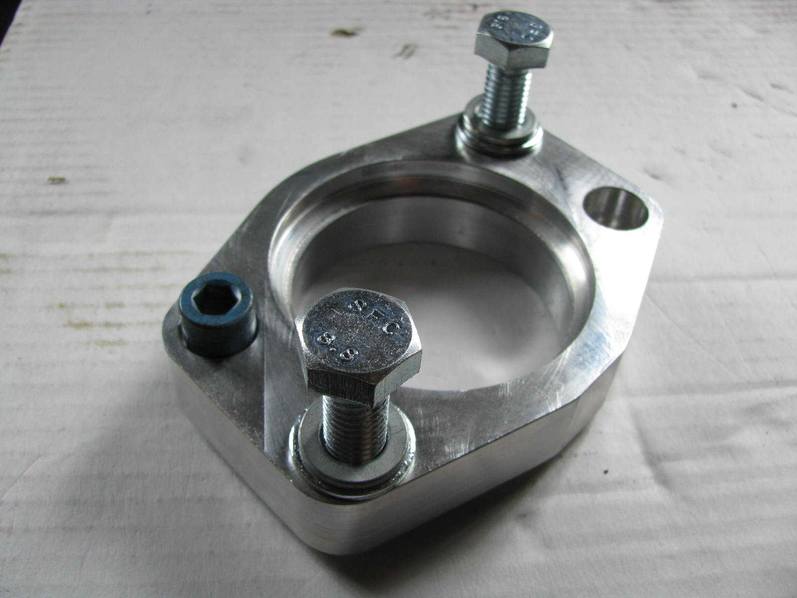
The original bus starter will not start this engine. There's no point in trying. Sell it instead. If you didn't get the donor starter, these can be expensive. I was very fortunate, and Justin gave me one that was making noise, but still worked. I have since had to replace it (the noise foretold it's weakening, and it eventually broke). Now, the TDI starter will start the engine, but it will not fit into the starter hole in the bell-housing. Remember the starter adapter I mentioned in the preparation post (See TDI install retrospective: Preparation)? They are from Westy Ventures (buy here). When I bought mine, they did not have one that fit the 002. So, I got the one for the automatic which was closest thing they had and trimmed away aluminum with a Dremel until it seated properly. Basically, I would dab some grease on the adapter and test fit. Where the grease had smeared off, it was hitting the bell-housing, so I'd trim a little bit. Wash-rinse-repeat until the adapter sits flush. Then bolt it up and then bolt on the starter.

Primary Wiring
With the alternator on and wired and the starter on, we're ready for the final piece: wiring up the ignition control. This took a considerable amount of time and research and the help of AndyBees. There are so many posts back in 2009-2010 as I wrestled through this, I couldn't possibly post all of the links.

First, we had the clutch pedal lockout. This was jumpered around at relay #3 (185 printed on it) so the starter will engage regardless of the clutch pedal position. Because of the weird nature of the wiring, it seems like other things could also prevent starting, like an open door or something. This is why we jumpered the circuit rather than fake a pedal switch. Oddly enough, I used the lack of this switch to move the bus around the driveway with the starter once. I don't recommend it, but in a pinch....

The computer needed to know when the key was in the "run" position to trigger switched circuits. I ran a wire from the fuse-box at front of the bus from a switched circuit back to the spare tire well where all the wires and the computer for the TDI reside. I had this wire trigger a standard relay to send 12V to the TDI ignition switch. After we suffered the ignition fire (See 4Peaks 2018 - Road Report), I moved the "switched signal" to come directly from the ignition switch circuit rather than piggy-back off of a random switched circuit as I had it before.

Out of respect for all of AndyBees' work and because he asked, I'm not going to post a picture of the ignition switch diagram. I will stress the importance of sending always-on power into both of the #30 female clips in the switch. This just needs to be signal-strength thin wires, sourced from a fused, always-on circuit. I am sure that if you asked (on TDIClub) he would bend over backwards to help you.

Last, we want to notify the computer that the switch was moved to the "start" position. I extended the original trigger wire from around the starter back to the engine bay, along the firewall to the passenger side and then up to spare tire well. This was also wired into a relay similar to the "run" circuit. Because of the manner of the TDI ignition switch, the "run" circuit needs to be energized when the key is in start position as well or the engine won't start. Since the bus is not wired that way, I wired a one-way diode (like this) from the start signal to the run signal to remedy: regardless of bus switch position (run or start), 12V is going into the "run" position of the TDI ignition. Then, from the other side of the TDI ignition, I traced the starter signal wire and extended it to the trigger plug on the starter.

Lots of text there, but basically, I extended the wires from the bus key back to the computer sitting in the spare tire well by using some bus wiring, some new wiring, a couple of relays and the TDI ignition. I have revisited the spaghetti of wires in the spare tire well before, and I intend to do another round to really tighten it up, but the wiring design as described above works, and has supported the TDI-in-bus for almost 10 years with an annual disconnect/reconnect cycle for the wires to relays and donor ignition switch.


Prior related posts:
Preparation
Fuel System
Physical Mounting
Vacuum System
Air, Inter-cooler and Exhaust

Next related posts:
Cooling
Secondary Electrical
ECU, dashpod and Sensors

Tuesday, March 26, 2019

MGB Charging System fun

Brief post today about an electrical breakdown deja vu but this time it's Oliver ('78 MGB), not Hapy ('72 VW).

Charging System Basics
Most cars have a relatively simple "primary" electrical system. There's the battery which holds lots of stored power for starting the engine and regulating the secondary power usage. That part is obvious. Wired into that battery are the starter and the alternator (or generator in older cars). These are motors for opposite functions. One, the starter, eats the most power while the other generates power. Connecting these together are wires and the ignition switch. Seriously, that's pretty much it for the charging system. There could be a voltage regulator (VR) between the alternator and the battery, but oftentimes these are integrated into the alternator so you don't need to worry about them independently. The VR is separate on the original '72 bus, mounted on the right side of the firewall in the engine compartment. There are lots of other things connected into the electrical system, of course, but for today I'm focusing on getting the the battery to charge.

And We're Talking about this Why?
from 123ignitionusa
Back when I had the MGB looked at by the local British car experts, they indicated that the charging system was sickly. I swapped out the battery. I still found myself charging the battery up an awful lot so I bought and installed an alternator upgrade (now at 105 amps). Neat. You can find them here. But the little car still died on the side of the road a couple of weeks ago, with an electrical failure. After our adventure coming home from Furthur in 2013 (See Tale of Two Trips) I knew what an electrical failure looked like. Lights dim, wipers slow down, fans slow down and then the engine starts to miss. Soon, it won't keep running and you're gliding to a stop on the shoulder. If there is one. The last tip: the hazard lights don't work. Which is especially great when you break down in an exit lane where there is no shoulder / break down lane. Like here: (45°28'37.3"N 122°47'25.8"W).

Fortunately, it was mid-afternoon on a Friday, so the traffic wasn't too bad. I got AAA on the phone and stood behind the little orange car in the sprinkling rain waving cars around me. While waiting for the truck, an ambulance pulled up behind me. One of the guys helped me push the car some of the way up the ramp. At the intersection, a couple of guys hopped out of a car and helped push the rest of the way up the ramp and around the corner to where I could turn onto Allen Blvd and coast downhill. I came to a stop around the corner on King and Lee where Oliver was loaded onto a flatbed.

Root Cause
LM 11009 (BA7s)
bayonet bulb
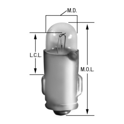
In my list of items included in the charging system, I failed to mention one last thing: the charging system failure light (labelled "Ignition"). This seemingly innocuous light bulb does more than just tell you when your charging system is fried. Of course, it does that and it is able to do that because of this other purpose. It provides a light 12v current to the alternator through a means other than the thick battery-direct cable. When that 12v meets another 12v coming from the alternator, no light. When the 12v meets ground, the light illuminates. Cool. This small 12v signal also initializes the magnetic field in the alternator so it can generate electricity. Without this little signal, there is no field, so no power generation, eventual system failure while you're trying to exit OR217. Neat. So, at some point after learning that my charging system was sickly, that little bulb died. Did I need a new battery? Maybe, the old one wasn't too old, but it was a discount brand. Did I need a new alternator? Probably, it was original and had the rust on it to prove it. Besides, 105 amps is far better than the 43 amps you get from the original or direct replacements.

top: blown bulb
bottom: new bulb
So, how do we prove this? Well, first, when you turn the ignition switch to run, you should see that little light. No light? Check the bulb. Assuming you missed that, or just want more proof, start your engine anyway and check the voltage at the battery while running the engine above 2000 rpm. If you're not seeing around 14v, you're not charging. Replacing the bulb is inexpensive ($2.50US per bulb at NAPA), though hard to get to. I was able to access it from under the left side of the dash by running my left hand up along the steering shaft, behind the tachometer. The bulb and harness are pressed into the plastic holder, and held in simply by friction. A slight tug on the harness will free it. The wires are kind of short, so getting the bulb down low enough under the dash so you can see and replace may be the hardest part. Well, that and getting the bulb and harness pressed back into place. Since I was up in there, I checked all of the bulbs, one at a time, to make sure I didn't have to get back up under there again any time soon. Fortunately, there was only the one.

Even if the "Ignition" bulb weren't critical to getting a charge, it is wise to run with all of your warning lights working. Gauges are great, but when you're enjoying the scenery or enduring bumper-to-bumper rubber-banding traffic, you may not note your gauges as often. A bright red light on your dash attracts the eye. And, in my case, I don't have a battery / charging gauge to tell me how well my electrical system is. I like the stock look, so I doubt I'll change that, but if I wasn't thinking about it before, I kind of am now.

Anyway, that's it for today. Thanks, as always, for following along.

Tuesday, December 5, 2017

Oh Clutch.

Today's brief post covers the swift demise of the clutch in Flash, the 2001 TDI Jetta.

Full Yard
The stable of cars in my driveway and garage has steadily climbed over the last few years. During my humble beginnings with the ex, I had the '72 camperbus (Hapy) and a '01 Jetta TDI (Flash). I fixed whatever car she had along the way, but generally speaking, I have the car I drove and the bus I worked on. When I met Boo, her 2000 Saturn (Dude) was her daily driver. She has had the same mechanic for that car for years, so I pretty much don't touch it out of respect for their relationship. Between kids' cars: '01 Jetta Wagon TDI (unnamed), '87 Jeep Cherokee (Jaws) the '79 ZX (not named yet) and my extra project car (the oft-posted about MG), our yard and garage have 7 cars packed in. Of those, at least 3 are daily-driving: the old Jeep, an FR-S and Flash the Jetta. The most often used of them all has been Flash.

Flash
He is a real trooper. After re-doing the front suspension a couple of years ago (See: Daily Driving), and replacing his steering rack after Les Schwab failed to tighten the baffles during alignment (letting water in and fouling the rack), he's been very reliable. He has crossed over 200k miles and while the body has looked better and there are all kinds of little things that bug me, he runs great. At least until a couple of weeks ago.

Oh Clutch
A couple of weeks ago, something in the clutch pedal went "pank!" and a little hiccup could be felt about an inch above the floor when raising the pedal from fully depressed. The clutch had been slipping a little bit in first gear, and I had started hearing some noise when the pedal was depressed and engine at idle. So, I knew something was going. As I write this, I'm inclined to think it's the throw-out bearing, but a new one of those comes in the clutch kit and in order to replace it, you need to get that far in anyway, so I started thinking about the job. And then things went from screwy to un-drive-able. We had started driving the FRS more, and Flash had sit for a few days when the need arose for me to drive Flash to work. The clutch started acting weird almost from go. Everything was fine so long as I didn't depress the pedal, which sounds silly, but I knew I couldn't make it to the transit center and then home again so I aborted the drive and turned around. I got home, but he was banned from travel until I do the clutch job.

Planning
As I mentioned at the top, I have 7 cars littering my driveway and garage. The garage is officially a 2-car, but you really can't fit 2 cars in there, though there are 2 doors. Behind door #1 sits the MG, without a top. It can't move out since the steady fall rains have arrived. So, I will need to do the job similar to how I did the last front-end job on the Jetta (replacing the steering rack): with the rear-end sticking out the open door. I really don't like the idea of the garage being left unlocked like that, so this will take some extra planning. But first, parts need ordering, and I need to verify I have all the requisite tools.

Parts
I really don't prefer car parts from the NAPA or O'reilly's of the world. The parts for some cars are okay, but for the European imports, they generally aren't that great. Since Discount Import Parts (DIP) closed their Beaverton location, I'm effectively forced to buying online. Fortunately, TDI owners have a few in-community vendors like IDParts.com who offer OEM and better-than-stock parts.

I like the dual-mass flywheel in the Jetta, and am choosing to keep it rather than swap it out for a single-mass. There are lots of cheap "conversion kits", especially at the NAPA's, etc where you can get a clutch, pressure plate and flywheel for $200. Sounds too good to be true? It probably is. Especially when a good clutch and pressure plate (with throwout bearing, grease and an alignment tool) is close to double that. If you're gonna spend 6 hours tearing your car apart, put in a good part, right?

So, I ordered the dual-mass flywheel fitting clutch kit ($300+). I decided to get a new real main seal as well. These run around $35, and are the last line of defense between your engine oil and your clutch. When these leak, oil gets on your clutch, forcing a new clutch job. I have not yet decided if I will replace the seal. I just figured that having it in-hand could stave-off Murphy's Law.

Tempted Fate
I thought I was being smart getting the rear main seal. Maybe I was. Unfortunately, there is something more serious going on within my engine bay that has me stumped. I can't start the engine anymore, and the battery dies after a handful of attempts. Maybe the cheap NAPA-replacement alternator I put in had gone bad. Maybe the recently replaced battery failed prematurely. Maybe my starter failed. Maybe there's something more serious happening inside like the timing belt or injection pump skipped a tooth. I don't know. I can say, though, that I entertained thoughts of simply parting the car out and thinning the herd of cars by one. Since the Jetta Wagon doesn't currently work (bad automatic transmission), now I got thinking of combining those problems: I take the working transmission and all the other manual transmission bits out of Flash, combine them with the new clutch kit into the Jetta Wagon and part out the rest of Flash.

And then I was able to get him started. It required a boost from my charger, but he started and I was able to back him up a few feet. Sweetness, the engine is fine. It's a pure primary electrical issue: battery, starter or alternator or a combination. A couple of days after I moved him, I tried to start him again. No start and the clutch pedal wouldn't return back up by itself. Neat.

Projects Pile
I'm increasingly loath to look out my front window at a growing list of broken things needing repair. Hapy needs a radiator. MGB needs a top. 280ZX needs a door and an interior. Dude needs a headliner. Jetta Wagon needs a transmission or a 5-speed swap. Jaws (the Jeep) and the FRS are the only consistent cars and Jaws' transmission is starting to go. Clearly, I'll have plenty of material for the blog. It's just a question of when I'll have the time to do the work.

The forces at work these days (holidays, boys need my time, icy weather approaching) have led me to the decision to take the clutch kit and Flash to the local clutch place to do the work. I can't drive him in his current condition, so I'll just haul him over there. I'll get the battery checked first (pretty sure this is it since an overnight on the charger doesn't get enough juice in there for the engine to start), but if it's the alternator, I'll need to do that replacement after the clutch is done. Since the clutch job requires the removal and re-install of a starter, I sent a replacement starter (from Discount Import Parts, so it's not crap) with the clutch kit and Flash. It is actively getting worked on, so if things go well, I'll be driving him home tonight.

UPDATE (2017-12-10): the no-start issue was resolved by replacing the starter. The new clutch is so easy to depress, the gears engage nicely and he starts right up. The Clutch Doctor did an awesome job and Flash is back to being our daily driver, shifting the FRS back to occasional use.

Thanks for following along, and I'll have something with pictures next time :)

Friday, May 26, 2017

MGB - engine mounts

One of the first things I noticed that needed to be addressed when I bought the little British car was the condition of the engine mounts. "How?" you may ask. I intended to replace the alternator belt and couldn't because the engine was sitting so low in the engine compartment there wasn't enough room between the bottom pulley and the front beam to fit a belt. Today's post covers the fun of replacing the engine mounts without removing the engine from the engine compartment.

virtually 0 clearance
Parts
This seems obvious, but there's more to the story than just the rubber mounts. They are sold individually, but they're not expensive. The originals are around 10$US, but there are upgraded versions for 13$US. If you're going through the trouble, it's worth the $6.

The mounts attach to the frame of the MBG onto mount points which are welded on, one per side. These have a vertical slot in the center for the body-side bolt on the rubber mount. The other side of the rubber mount attaches to an engine mount bracket. With the age of these cars, the bracket often has issues hidden behind the rubber mount. My passenger-side bracket was both bent and cracked. Neat. These were $6 a piece. So cheap. Crazy cheap compared to modern cars or even the old bus.

Last, you'll need fasteners. Those old nuts, bolts and washers are as old as the car, and probably more rusty. These old British cars have lots of different metals in them, increasing their tendency to rust. So, get stainless if you can or zinc-coated if you can't. Plain steel will rust again. All of the nuts and bolts fit a 1/2" spanner except the nuts which fit inside those welded-on mount points on the frame and the lower bolt on the bracket. Those are 9/16". To replace the mounts and the brackets, I got 8 1/2" nuts with matching lock washers and 4 bolts, each just 3/4" long. These are all fine thread. I also replaced the bolts on the bottom of the mounting brackets. They need to be 3/4" long. I tried longer bolts but they bottomed out.

Tools
bent bracket on right
Similar to most of the other projects I've done on this car, the tool list grows as fasteners get harder to reach or harder to remove. PB Blaster (or a like product from the WD40 folks) is critical. 1/2", 9/16" sockets and wrench. Spanners in the same size plus a breaker bar. Floor jack and a small piece of wood 2x4. With all that hardware, the single most important tool is your patience. I kept running out and having to go looking for more.

Process Out Prep
I read a bunch of different opinions before I started. While the mounts are usually replaced when the engine comes out, it isn't required. Some have found that removing the steering isn't necessary. Not me. I couldn't have imagined this with the steering still in place. See, the steering column runs straight through the welded on frame mount on the driver side, making it all the more difficult to address the nut contained within. Some folks have taken a cheap spanner and ground it down thinner to fit between the column and the mount. Fortunately, I still had my steering unit out, so this was academic for me. My advice: remove the steering rack. See how in (MGB-steering rack).

On the passenger side, the alternator blocks easy access to the mount. This is very easy to remove, and you already have the right tools: 1/2" socket to loosen the belt and then a couple 1/2" spanners to remove the mounts on the top. Don't forget to unplug the 2 wires on the back. And, just like that the alternator is out and you can easily see the mounts.

Once you have clearance to get at the mounts by removing the steering rack and alternator, you're pretty much ready to go. Jack up the front end and put it on stands so you can easily get after it from above and below. Then, put that block of wood on top of your floor jack and set the jack under the rear edge of your oil pan, where it meets the transmission. This is it's strongest point. Raise the jack until the weight of the engine is mostly removed from the mounts, and is instead on the jack/wood combo.

Process Out
Pick a side. To stretch my patience, I would do a little on one side until I grew frustrated and then moved to the other side. Start with the nuts which hold the rubber mount to the bracket. These are the easiest to get to. The bolt closest to the driver doesn't have a bolt head on it so it could free-spin on you. Yes, that's frustrating, but with some pressure applied with a screwdriver between the free-spinner and the engine block, I was able to get the nut off. Next, get after the nut that is semi-captured within the frame-side mount. A spanner can only move about 1" up/down at a time, and then you need to flip it over or use the box-end to move it another inch. This tests patience. Once the nuts are removed, raise the engine until you are able to free the mount from the bracket and frame mount. I also leveraged my breaker bar as a lever to tilt the engine a little bit so I didn't have to raise it as much.
right (p-side) replaced

With the rubber mounts off, remove the bolts holding the brackets to the front of the engine. Last, remove the bolts on the bottom of the brackets. This last bolt is very hard to get to until after the rubber mounts are gone, and even then it is partially obstructed by the sides of the bracket. Patience. Once the bolt is loose, I was able to spin the bracket off by hand, not bothering with anything other than a socket on the bolthead to keep it moving with the bracket.

Process In
The install is the reverse, but it was advice like that which inspired this blog all those eyars years ago, so I'm going to run through it. Start with the bolts for the bracket. Don't torque it down, just get it threaded on and then shift to the smaller bolts which attach the bracket to the front of the engine. The bolts go in from rear to front. While this may not look as clean, the rubber mount will dig into the end of the bolt sticking rearward if you don't do it that way. Yes, I did this first. Once the bracket is loosely attached, torque down the smaller bolts and then the large one. If you do it in the other order, the bolts in the front part of the bracket can get hung up on a slight misalignment and you'll have to do it over. Yes, I did this too. :)

With the brackets in, re-raise the engine so you can fit a rubber mount in. I did the driver side first, but I don't think it matters. The driver-side bracket has that one weird bolt that doesn't have a head. I found something that would work at the hardware store, but needed to bore out the hole in the bracket to get it to sit deep enough so the bracket would align properly on install. Crazy. Once that is solved, plop the driver-side mount onto that bolt and shift it into position such that the frame-side bolt is in the vertical slot. Short sentence; could be a long effort. I used the breaker bar as a lever to help that last little bit of space to slip the frame-side bolt into the slot. Get the lock washers and nuts onto the bolts. I found gravity to be a terrible partner in this, causing the frame-side nut to fall off the bolt and down into the nowhereland of garage floor multiple times. Patience. Once the nuts are threaded on, tighten as far as you can without tools. Remember how hard it was to get the spanner in that frame mount during removal? Yeah, just as hard on install.

left (d-side) replaced
Once you have the nuts threaded on as far as you can by hand, give them a couple of runs with a spanner and then lower the engine so the jack is no longer holding any weight. I tried to shake the engine a little bit on its way down to make sure it settled, but it didn't seem like the engine moved at all. Just the same, its a good idea. Once all the weight is on the mounts, finish the tightening with a spanner.

Finish up by re-installing the alternator, and the steering rack. Lower the car off the stands, clean your hands and your tools.

This job was a bear, but the engine sits at least an inch higher than it was. Between the bent and cracked bracket and the twisted / flattened mounts, this job was long overdue. While the engine won't run any better, I'd like to believe that any vibrations will be greatly reduced and the drive train is now aligned like it should have been coming out of the factory.

As always, thanks for following along. For my American friends, have a pleasant Memorial Day weekend. I greatly miss the old Hornings Hootenanny which used to fill my Memorial Day and am left unsure what to do with my 3 days this year. Maybe I'll pull out the welder...

Sunday, October 12, 2014

Back Together, Test Drive

In my last posts, I covered the hazardous re-assembly of the engine-to-transaxle and the install of the combined unit at 15*.  Today, completes that journey.  In order to do the re-assembly as quickly as possible, I tried doing it a little differently.  I usually do system by system.  This time, I did it based on where I was and did everything I could before I moved.  I'm not sure I'll do that again, but it was interesting.  I cleaned every part with brake cleaner before installing it.  It made a world of difference, and I'll do that every time now.  Handling a clean part is just so much better than the oily, greasy alternative.

Lower Right Rear
Starting below the right side of the engine, there are a few things to do, starting with the CV joint.  I place a jack under the lower shock-absorber mount and lift until the tire just barely leaves the ground.  Then, with 6 new Allen-head bolts (one striped last time), attach the CV joint to the side of the transaxle and drop the tire back onto the ground.  At the front of the transaxle on the right side, is the ground strap.  It requires a 13mm socket.  Install the starter.  It requires a 17mm socket (need to verify) for the 2 bolts plus a 13mm for the B+ cable from the battery.  Plug in the trigger signal wire to the starter.  Connect the B+ wire to the Atlernator and plug in the sensor wires.  Double check all the other visible sensor wires (like on the cooling system) are plugged in.  Last, zip-tie the cooling pipes up out of the way from the axle.

Rear
Put in the rear support bar.  Don't forget to put the rear bumper mounts back in when you do the bar; they use the same bolts.  Install the support tower and the rear engine-frame mount.  If you get this far and the mount isn't lining up, check the support bar install.  If the mount and tower are on different angles, you probably mated the engine to the transaxle at something other than 15*.  Go back one posting :)  Once the rear mount is in, hook up the exhaust.  The muffler pipe has a hook that fits onto the rubber mount which is hanging off the right side of the rear support bar.  Once hanging, it should fit with enough room to maneuver the rest of the pipe without it hitting the ground nor the bus and no jacking required.

The exhaust-to-turbo mating has a gasket and 3 13mm nut/bolts.  One mount is a stud coming out of the turbo.  Because of the design, at least one of the 13mm needs to be tightened with a wrench instead of a socket.  Next comes the intake system.  Start with the non-charged air pipe from the air cleaner to the turbo.  This is held on with 10mm bolts, and most of the work is from above rather than through the rear hatch.  Next, the charged-air plumbing with the intercooler is most easily installed as a unit.  Slide the turbo-end on first, then set the intercooler and complete the system to the intake last.  The pipe clamps are a combination of slotted-screwdriver and 10mm socket.  The intercooler is held in place with bailing wire (yes, bailing wire) looped between the mounting hole on the intercooler and the open loop in the engine mount attached to the engine.  This allows for the vibration of the entire system to resonate as one.  Route the vacuum to the turbo and snap it into the channels on the plastic tubes.

Lower Left Rear
Shifting back under the bus, repeat the CV joint process for the left side.  Verify what's been done thus far from the new perspective: the turbo plumbing, the air system, the vacuum.  Hook up the bowden tube and the clutch cable to the clutch activation arm.  If you run out of adjustment threads, you need some head-washers (I used 4) between the bowden tube and the mount it slides into.  That mount is held on with 2 13mm bolts.

Lower Middle
Mount the nose of the transaxle.  Plug in the reverse wires for the reverse light switch.  Don't brain yourself on the radiator.  Thread the short hollow tube to connect the gear selector at the front of the transaxle to the long gear shift tube coming from the front of the bus.  Zip-tie the tube into place.  I'm sure that last line will upset some purists (as if the whole project hasn't already), but the original bolt/nut solution falls out; the zip-tie doesn't.

From Above
There's little left now.  Mount the coolant overflow bottle, verifing the top coolant line runs where it's suppoed to.  Plug the sensor into the bottle.  Note the coolant level, and come back and check again if its not spot-on.  Verify the vacuum bulb is set and tight.  Put the fuel filter into it's mount and tighten it down, making sure that the lines run properly.  I have a cheap $1 clear filter in front of the spendy stock filter to extend its life, but it also shows me that fuel is getting that far.  I check that for a fuel level at this point.

All Over
Last, the battery is hooked back up.  Before that, all of the electrical connections, including all sensor plugs should be double checked.  This is where the "do everything you can see" model falls apart.  By doing it one system at a time, you know everything was done.  By working zonally, you don't really know for sure without checking system by system.  At that point, you may as well have just done it that way.

Testing
This is the part everyone wants to jump to: grabbing the keys and giving a test fire.  The first time I tried this time around, I got nothing: I'd failed to hook up the battery.  Once resolved, he started right up.  I applied the clutch and shifted through the gears.  Nice and smooth.  Seatbelt on, and on the road to test.  There was less noise than I remembered.  The gears shifted easily up through 3rd (never got to  4th), and the bus felt peppy.  Overall, it was a great, albeit short, drive.  I declare the bus road-worthy again.  By the way, there wasn't a single drop of oil on the transaxle nor engine after the test drive and cool-down.  Success!

Thanks for following along.  Next time, I look at the ceiling of the bus and/or knocking the dents out of and painting the rear bumper.

Sunday, October 13, 2013

Flash Lives!

Since the trip to WA, the Jetta (Flash) has sat where the tow truck dropped him.  Today's post is about my successful efforts to get him operational.  I did want to update on the MPG we got on the Eugene run: a few tenths over 30 MPG burning around 7.5 gallons door to door.  We probably could have done better had we not been cruising over 65mph on the way down.  Still, that's almost twice the miles per gallon (used to get ~16), a more responsive throttle, more power and, of course, non-explosive made-in-the-US bio-fuel.  Sweet.
Now, about that Jetta with the electrical failure...

Get Back to Base-line
Before you can diagnose anything electrical, the battery needs to be at operating voltage first.  I've gotten so much mileage out of my battery charger.  It is the one non-tool appliance I simply couldn't be without.  After charging overnight, and holding charge for a few days, I felt confident the battery was not the problem.  Moving on to the next likely suspect...

Verify Wires
Old Alt on left. New on Right
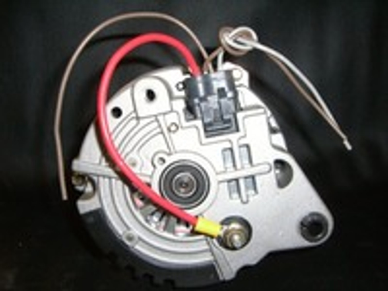
So, if you think your Alternator is bad, its wise to first make sure that its not simply a case of the alternator not getting the message to generate power.  On the original engine in the bus, an external voltage regulator would figure this out.  By simple comparing the voltage on the battery against a target 12V, the voltage regulator tells the alternator to produce juice until the battery is at 12V, and then it dumps the power.  So simple.  In the modern engine, determining whether power is needed doesn't fall on the voltage regulator.  There's a computer involved now, so the new alternators have an additional plug on the back.  Tapped into that plug is a 2-wire clip-in.  With the key tuned to the "run" position, both of the wires should register voltage above 5V.  In my case, both wires showed 11V, so the risk of damaged wires under the battery (there's a junction there that can get damaged) was averted.  As "easy" as a wiring problem may sound, knowing its the alternator was actually a relief.  I've found that re-wiring stuff is error prone.

Access the Alternator
Serpentine belt path in TDI
It isn't exactly easy to get an Alternator off of a TDI engine.  The old aircooled bus engine was, though: 2 bolts, a single dedicated belt and a backing plate.  The only hassle with that set up was the small rubber "hose" that routed cooling air into the alternator.  It was easy to tear, hard to get to and difficult to source.  The new TDI engine is another whole deal.  I followed this process over the course of 2 days: one to remove and one to install, spending about 3 hours each.  While the process is correct, the poor visibility into the area where all the bolts are makes it harder than it reads.  I found looking at the engine in the bus was useful for showing me were the bolt-heads were.  Funny, I thought having 2 of the exact same engine would make it easier to work on the bus.  Lately, the opposite has been more the case.  Remember, when playing with electrical, disconnect the battery once you start taking stuff apart.  Creating an electrical short with those thick wires can go very badly.

DSO in PDX
Autumn approaches.
taken on Nike campus
Between the removal of the old alternator and getting the new one, Boo and I caught Dark Star Orchestra at the Crystal Ballroom.  They started strong with a "Music Never Stopped" -> "Going Down the Road" -> "Good Lovin", but the crowd energy didn't reflect the energy coming from the stage after that.  Maybe it was the "Mission in the Rain", but after the first 3 songs, the crowd energy turned negative.  I don't mean bad, I mean polarity: negative.  On a whole, more people were pulling energy from the scene than were feeding into it.  Boo and I left early, during the segue from space into Unbroken Chain.  I haven't left early since Jerry died, and even then it was just bailing on encores to get coolers of beer ready for the post-show sales.  I don't think that's DSO's fault; I put that on the Portland crowd, though DSO was crowd-detached too.  Some of this is their fault, but I think they picked up on the same thing we did.  Too many hipsters sucking all the groovy out of the room and not enough hippies to put it back.  Polarity Negative.
While I'm glad DSO has a new full-time dedicated bass player, he's just okay.  Skip seems nice enough, but he doesn't approach the instrument like Phil Lesh does, remaining on the root of the chords most of the time, and only putting in the fills that have been baked into the original songs.  Come on, Skip!  Bring that creative side to the masses!
EMPI replacement ignition lock

That's about all I have for today.  After monitoring the serpentine belt, I changed the oil & filter, and Boo and I took a test drive to dinner.  The Jetta is back to operational.
Next, I'll be looking at the ignition lock on the bus.  The original has a lockout bit that has become increasingly temper-mental.  Replacing it requires removing the steering wheel, tearing down the steering column, and then some careful surgery on a work bench.  Should be time-consuming, but well worth the effort.

Saturday, September 28, 2013

A Tale of Two Trips

Since I last posted, Furthur announced they wouldn't tour in 2014.  Within a week of that announcement, VW Brasil announced they would stop production of the VW Kombi (bay-window bus) at the end of 2013.  While seemingly unrelated, for those who drive VW buses around the country to see music, this was quite the double blow.  The day after the VW Brasil announcement, I bought a pair of tickets to see Furthur at Marymoor Park east of Seattle to compliment the pair I already had for the following night in Eugene.  Today's post covers the 3-day adventure.

Getting Out of Dodge
Tuesday is a typical workday for me and the Marymoor venue is 3.5 hours from home with good traffic.  Since the show started at 6,  We had to leave by 2 to have any hope of seeing it start.  I'd written off the lot scene.  Work was, well, work, so I didn't actually get Boo and start driving north until almost 3.  With the compressed timeline, we left the bus at home and took the more consistently reliable Jetta.  As speed limits rose, the rain intensified.  We rolled music off my iToy to keep the mood calm.  Outside Fort Lewis, emergency vehicles were on maneuvers, jamming up traffic in both directions without any actual accident scene.  Lost 20 minutes.  We hit Olympia by 5 and the rush hour traffic that usually arrives with evening.  The Jetta handled well, drove fast, and we found the venue with very little trouble.  We arrived less than 30 minutes late, only missing the first song entirely.  We heard the second while parking and the third while walking to the gate.

Marymoor
Marymoor Map
We met our friend Grateful Ed just inside the gate.  He'd driven up much earlier in the day at a much less frantic pace.  Being a park, he was able to settle before 2, fell into a photo shoot for REI and pre-func'd with some heads from WA.  He'd landed us a spot less than 40 feet from the stage, and led us in to a nice 1/2-Step.  As a location to see music, Marymoor is fantastic.  It is one large flat lawn with a small berm ringing the outer edge.  On the other side of the berm are food carts (though the food options were weird and lines non-moving), beverage gardens (no line) and the restrooms.  Aisles through the lawn are painted: no railings, fences or concrete.  I'll absolutely go back for more shows there.  I just wish they'd have some back-to-back nights and a place to overnight camp nearby (EDIT: found a place: Vasa Park Resort).  The crowd was older and small.  We didn't see any wookies either, so we figured that the folks traveling with the band skipped this show and we'd meet them in Eugene.  The show was good, the second set really good with a foreshadowing "Goin' Down the road Feelin' Bad" encore.

Let the Real Adventure Begin
Since Boo and I hadn't eaten since lunch, and it was almost midnight as we left the lot, we concluded we should grab some eats before heading back to Oregon.  A Denny's stop with Ed later, we're ready to go.  Boo and I had been having some sporadic battery issues with the Jetta around town, with the battery light popping on after starting.  After driving for a bit, the light would go out, so we didn't pay it much heed.  I figured the alternator was failing, and had it tested.  "All good," says the mechanic.  I tossed the car-battery charger into the backseat anyway.  So, as Boo drove us through that construction zone between Seattle and Tacoma, we started to get some weird idiot lights firing.  The battery light was already lit, but the ABS light started to flash and the radio started to cut out.  We turned off the radio, but the ABS light stayed on steady.  The air-bag light then lit up.... then the dashboard lights started to dim... the blinkers stopped working.... the headlights turned off... Within a couple minutes we went from safely following Ed down the I-5 to completely failing electrical system.  We couldn't raise Ed on the phone, so we douche-dived the first exit we came upon: Tillicum, WA, and rolled into the Chevron.  While the engine idled, I spotted an electrical outlet on the side of the building.  We hooked up the battery charger and watch the idiot lights turn off one by one.  Boo asked (and was denied) to use the Chevron bathroom and got us a water.  After 15 minutes of charging (1:50AM), we figured we'd gotten enough juice to get going again, but we had the failures cascade again before we made the freeway on-ramp.  We were lucky enough to get back to the Chevron before the engine died.

Tillicum
from Google maps
Sitting in the middle of the Chevron lot in the wee-hours of the morning was surreal.  An older boy / young man was peddling a bike through the lot and helped us push it into a parking spot.  He then asked for a smoke and rode on.  I called in AAA for a tow home, and learned than my membership got 100 free miles.  The remaining 40 were my problem, but the driver would be there within an hour.  Once we got the immediate problem resolved, Boo and I looked around at where we'd landed.  Sketch.  Very Sketch.  Cyclone fencing, closed businesses and boarded up cheap apartments.  Sweet.  We saw the Taco Bell and McDonald's down the street had their lights on, so we walked down there to sit and wait.  Neither business was open, and we concluded they left the dining room lights on to reduce break-ins.  On the walk and wile waiting in the car, we got a more intense sense of how sketchy the area was.  The young guy on the bike kept re-appearing, clearly following a route from one location to another.  A a light blue cab stopped at the Chevron multiple times (though that could have been innocent enough).  And a young woman all dressed in black appeared multiple times, dashing from one boarded up location to another.

AAA
The flatbed tow truck arrived shortly after 2:30AM, driven by a guy with a long chin-strap beard that ended flat (like ZZ-Top).  He reminded me of a gnome with a plumber's crack.  While hooking up the car, he admitted that he'd worked until midnight, had worked the night before, and had very little sleep.  We climbed into the cab, and Boo told him that we needed first to stop at a restroom.  The driver flipped a U-turn, led her into the Chevron and got the clerks to let her use the restroom.  Apparently, they don't let customers use the restroom because they've been robbed so many times.  Awesome.  With thoughts of "lets get the hell out of here", our gnome wheeled to the freeway and we nosed south.  The truck was bouncy, the bench seat nearly as hard as a bleecher, but fatigue finally caught up to me.  I was awakened by a few big bumps, as was our gnome-driver at least once, motivating Boo to stay awake, chatting him up so he didn't fall asleep.  Her sacrifice meant I could sleep (we thought she'd sleep on the drive to Eugene), and I didn't awaken for good until we were on the Freemont Bridge watching dawn break over downtown Portland.  The Jetta was tucked away on the driveway at 6:AM, and after refusing a cup of coffee, the driver-gnome took my $160 for the 40 miles of towing and headed back to Washington.

Hapy
Boo hadn't slept for more than 15 minutes, and I'd gotten about 2 hours of rough sleep, so we decided to take a nap or a few hours before thinking about Eugene.  At 9, we hosed off, scarfed some instant oatmeal, and started loading the bus.  Since we were going to overnight in Boo's sister's driveway, we didn't need much camping gear, just sleeping bags and food.  We'd agreed to meet at Grateful Ed's at 11:30, and we arrived a few minutes early.  Hapy (the wonderbus) needed to get his gears warmed up, but once we got to operating temperature, he handled great.  I'd driven him to work and back a few times last week to get some confidence up and to confirm that the leak was solved.  Once Mayhem arrived at Grateful Ed's, we started the carabus south, taking turns leading.  Hapy can cruise at 60mph with the RPM's just under 3k.  We discovered that pushing the RPM's above 3k increases the noise significantly, so 60mph became the standard cruising speed.  Because of the late start, we drove straight to the Cuthbert Ampitheater parking lot, agreeing to meet Boo's sister and husband there.  We arrived just after 3, and got a prime parking spot along the main strip (parked with sliders facing each other), but not on Shakedown Street.  We did not see many other old buses, but the few we did see were close by.  Again, we leveraged the removable middle seat as a lot couch, creating seating for all 6 of us easily.  I'm really loving that.  On the whole drive, Hapy's temperature never hit 190*, and stayed at 185* almost the entire time, only climbing above after pulling uphill.  He handled very well, making the drive to Eugene the highlight thus far.

Cuthbert
Furthur farewell
The Cuthbert Ampitheater, unlike the Marymoor, is almost completely pitched ground.  The front now has reserved seats, but the concrete is not flat.  Behind the seats is a narrow non-flat grass area where seats are not allowed, backed by a 18" drop-off down to a cement walkway.  Behind the walkway is the steeper lawn where low beach chairs are allowed.  Simply standing on that grass wears on your muscles like running downhill.  Now, try dancing for 3 hours.  Yeah, that can hurt, but its worth it when the show is smokin'.  They started with a Brother Esau, and kept it funky throughout.  The crowd included many more of the usual road-warriors, supporting our thoughts about them skipping WA.  It also included many of the Oregon old-guard 60's-era hippies.  We sat next to a couple who drove in from the coast, for example, who had been seeing forms of the Dead since the mid-60's.  Ken Babbs was there.  Very cool when you contrast that with the kids dancing on the walkway who were born after Jerry died.  Unlike 2 years ago, the scene in the lot after the show was much more calm.  The staffers weren't trying to cowboy the concert-goers out of the lot 20 minutes after the last note was played.  There were tour-heads swinging beer, T-shirts, posters and coasters.  For the first time since the 90's, I heard a nitro tank filling balloons.  

Homing
Belle heading home
Boo, her sister, Grateful Ed, Mayhem and I skipped the after-party, but Boo's sister's husband went and closed The Cooler.  The band played until almost 2:AM.  If we'd gotten more sleep over the prior couple of days, maybe we would have gone too.  Instead, we tipped a couple beers, played with Boo's sister's dog and visited in the comfort of the old hippie Dr. Seuss house.  We grabbed breakfast at Brail's and headed north.  Hapy again, drove like a dream.  This time, Ed led the carabus (see picture at right), setting a slightly slower pace to help keep his temperatures down.  That also lowered the noise in my bus a little bit, making the drive all the more pleasant.  We got home a little after 2, making the entire Eugene run, including to/from the venue, Boo's sister's house, grocery stops, etc on less than one tank of diesel.  I'll know my actual mileage when I fill again, but I figure I drove 250 miles and I put in just under 10 gallons before leaving home.

As always, thanks for following along.  The long trip with the bus has helped me understand what needs to be looked at next (adjust shifting linkage, headliner, deep-cycle battery charger, tighten steering, better seal for engine hatch, fuel gauge, painting the exterior...).  The journey is the destination.