Showing posts with label temperature sensor. Show all posts

Tuesday, April 21, 2020

Oil Pressure and Temperature (Part 1)

While working on the TDI install retrospectives, it occurred to me that I did not have visibility into the oil system. It bothered me that I did not even have an idiot light to tell me my oil pressure was too low. So, I started working through how I could solve. Today's post starts us on that journey. I started this before the winter holidays, but I'm only really getting down to it now. I had a significant Paulie Axiom event this past week that reminded me of this old post. The Axiom still holds true; I have new examples almost every week.

Sensing
VDO 360 006
It starts with collecting the oil temperature and pressure information. As I mentioned in the final retrospective (See TDI Install Retrospective: ECU Dashpod and Sensors), the pressure sensor in the oil filter housing does not send an "honest" pressure. It somehow sends a relative pressure, so you can't just tie into it for a gauge. I don't want the ECU to freak out because there isn't a pressure signal either, so we need to find a good spot. Our friends on TDIClub (RacerTodd, specifically, on this thread) have located a good spot for collecting the oil pressure and temperature from the oil filter housing. In the picture at the bottom, nicked from that thread, the yellow circle is the spot. The thread size, according to him, is M10x1, which aligns with the thread size/pitch of a standard VDO sensor.

So, with this information, I collected (in late Fall, 2019):
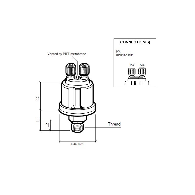
VDO 360 006: oil pressure sensor with the dual idiot light (7psi trigger) and gauge posts,
VDO 323 423: temperature sensor (300*F/150*C Max),
VDO 323 088: temperature sensor (250*F/120*C Max) and
VDO 240 850: sensor splitter / adapter so 2 sensors can run out of one spot

I am concerned that I need an adapter because the temperature probes are so long that it would bump up against something inside the oil filter housing. We'll see. Just in case, I had a sensor that was 1/8npt thread so maybe I can figure out an adapter instead. I also got a shorter sensor that tops-out at 250*F/120*C. I'll get to the sensor stuff later.

Wiring
note unused spot to right of speedo
AND a gauge where your right
knee would be. Huh?
I had intended to run one thick cable from stem to stern for all of my not-typical-bus wiring. Then I considered each circuit individually. This led me to a different decision: 2 thinner cables. Here's why: In the ECU Dashpod, etc posting I linked above, I listed out a number of circuits. Many of these wires run from behind the dashboard (or at the foot pedal) to the spare tire well at the very rear on the driver side. When I add in the desire for idiot lights and a couple of gauges, the number of circuits grew by 5 or 6, but none of them went to the spare tire well. They all ended in the engine compartment where the sensors were. So, rather than plan for a thick cable of, say, 20 wires, I can split that effort into 2. First I will focus on the 6-wire cable that will deliver the signals for the oil temp gauge, the oil pressure gauge and the oil pressure idiot light. Eventually, it will also deliver an Alt idiot light and a low-water idiot light. I'll leave the last wire open so I have it available for something I haven't thought of yet. I'll post on the snaking of that cable after it's done. Depending on the weather, maybe that'll happen soon... or in mid-July. Love those wet Oregon springs.

Gauge(s)
Last consideration is the gauge or gauges. With VDO sensors, VDO gauges are the logical choice. Buses delivered with VDO stuff, so this is staying consistent with original intent as well. Most bay window buses have a blank spot on the dash to the right of the speedometer. Some folks have retrofit a clock or a tachometer in there. Mine is the standard blank plate held on with 2 8mm screws from behind. The visible space within this hole is about 80mm in diameter. A typical VDO gauge is 2-1/16" (52mm). Simple math says that 2 52mm diameter gauges cannot fit into a single 80mm hole. So, I thought about how I could get creative.

which one is the altimeter?
Creative idea 1 - have the lower half of one of the gauges hidden under the bottom of the ring. This sounds great in theory, but the 8mm screws which hold things to the back of the dash are located at 12 o'clock and 6 o'clock. The 6 o'clock one would prevent any gauge from hanging below like that. I considered setting it off to one side that way, but in order for the housing of the gauge to clear the screw, it would be oriented at 4:30 or 7:30 and look real janky. Plus, the upper gauge would be pushed so far up, the top edge of that gauge would not be visible. So... idea FAIL

Creative idea 2 - get one of those 2-gauge housing things and set it on top of the dash. Okay, this isn't terribly creative. Quite the contrary, this is the obvious idea, but to me it looks so bad. Just look at the picture above. I mean no offense, but the aesthetic just isn't there for me. Currently, my dash top is clear. If I were to add one of those, it would meet the need, but I think the looks would bug me every time I got behind the wheel. Beauty is in the eye of the beholder...

classic 2 gauge housing
Creative idea 3 - get one of those 2-gauge housing things and attach it to the lower front of the dash facing up. To give you a better idea, consider that when sitting in the driver seat if you were to look down at the steering wheel and look through it, you would be looking at a warning sticker attached to the steering wheel support. If a gauge housing were placed there, it would be relatively easy to mount, easy to see and it wouldn't get in the way of driving nor your legs, unlike the first dash picture where the gauge is right where your right knee would be. This was the leading candidate until I had creative ideas 5 and 6.

Creative idea 4 - get one of those 2-gauge housing things and attach it to the shelf up where everyone else has sun visors. The problem with this one is that the space between the shelf and the ceiling is too short to fit a housing, so it would have to be attached with just a simple ring-mount. They are not pretty, but would work. I would also have to route the signal wires plus the illumination power up there from somewhere. The extra wiring would prove difficult to hide, further detracting from the aesthetic.

part number 911.641.103.x
Creative idea 5 - get a Porsche combo gauge and fit that into the spare hole. "What's that," you ask. Porsche has VDO gauges stock just like the bus does. They have a 100mm diameter dual gauge that has the oil temp and pressure as well as integrated idiot lights for the alt/generator, and oil pressure. Some of them also included a brake warning light. These run for over $125US on eBay. The biggest problem with this idea is the overall size. If the gauge is 100mm but the hole is only 80mm, then we lose 0.4" in radius, which may effectively block the visibility of the outer edges of the gauges, just like in creative idea 1. There exists an 80mm version of this combo gauge, but I have been unable to find it used, and new it is, like, $325US (well, it is a Porsche part), so that's not going to happen. I don't think this size was produced for many models nor years.

Creative idea 6 - get the participant bits of a Porsche combo gauge and make your own. This sounds a little nutty, but hear me out. If all I need are the 2 small gauge bits, and I can eliminate the extra space between and around the 2 gauges, perhaps I can assemble a combo gauge that fits. I don't know about idiot lights, but first things first, can just the 2 gauge pieces fit? I mean, somehow the Porsche and VDO people figured out how to make one fit into 80mm, and I sincerely doubt they made special one-use gauge innards to fit that slightly smaller footprint. Considering what this guy did, my idea is not that far-fetched. He built his own multi-gauge from the working innards of off-the-shelf VDO gauges. Very cool.

---

nicked from TDIClub
If you've read this blog for any length of time, you know I have to try ideas 5 or 6. Could it be more expensive and ultimately look worse than any of the other options? Absolutely. Could it possibly not even work, forcing me to do one of the other options? Most definitely. But it is this kind of thinking that got the TDI engine into the bus in the first place. So many people said that couldn't be done, or it was a bad idea or that the engine couldn't withstand running at whatever RPM or putting a water-cooled engine into an air-cooled bus was blasphemy. I was even told to sell my bus to someone who would appreciate it and go buy a mini-van or a Sprinter. blah, blah, blah.

So, while we were just learning about some new virus discovery in China (not a dog whistle, just saying that as a reference to a point in time) and a possible first case in the US, I bought one of these Porsche combination gauges off of the UK eBay site for less than $125US delivered. I will see how it looks in the blank spot before I start removing the individual gauges and update as I go. Unfortunately, the VDO folks don't know much about their old no-longer-available gauge components like these, especially when they were built specifically for a car manufacturer. I direct messaged with their staff, and that was fruitless. So, while the old Porsche/VDO combo gauge may look the best, supporting it long-term will be difficult. Ultimately, I may either have to go with one of the other options or build my own out of widely-available VDO gauges that I tear apart like that 914world poster did. I have both an oil temp and an oil pressure from VDO sitting in my garage from back when I had the original engine, so going that direction would kind of be free. Just time consuming. Here's a PDF describing a few gauge-cracking methods if you want to give it a try yourself.

Thanks for following along, and if you have any suggestions for other ideas, or opinions on the ideas I've floated, I am absolutely open to hearing them. I just have to try idea 5 first.

Tuesday, October 15, 2019

Adventures with Nemo

No, this isn't a post about a clown fish. Today, I'm going to cover the adventure of trying to get Nemo, T's A4, to operate correctly again.

Break Down
This story actually starts very soon after the last post about A4 ended (See A4 Puzzles). It was late Summer, and T had been living with us for a while. His car had been behaving well, but he wanted to make sure everything was tip-top before leaving for Eugene. Well, we got it running, but he broke down with a coolant leak on the way to Eugene. We knew the radiator had a small leak, and we concluded that the leak was the cause. I drop-shipped him a replacement which he installed in his garage. Unfortunately, this was not the cause of his coolant loss.
T replaced the coolant outlet flange. Twice.
He replaced a few hoses.
He swapped the coolant overflow bottle with a used one from the junk yard.
By the end, he was no longer seeing coolant puddles appear under the car, but when he would return from a drive the coolant bottle would register below "MIN". Frustrated, he had the car towed home, to Beavo. He rode with the tow truck driver and borrowed Flash while K2 and I assured him that we would find the cause and fix it.
That was in June.

Rad Patch
K2 was out of school and missing his daily shop time, so we thought he would get into fixing the A4. Well, that didn't last very long as Summer brings its own distractions and rewards. So, while he took some air, I re-assembled what K2 had started (he was preparing for a head-gasket job) and got Nemo to start again. I had forgotten that I had drop-shipped a radiator down to Eugene, so I started to disassemble the front to remove it. I discovered that one of the fasteners holding the air conditioning condenser to the radiator was a screw instead of a bolt. AND, the tip of the screw had pierced the plastic side-tank on the radiator, causing a leak. So, I started with that.
I used an old Shade Tree trick for small (read: pin) holes. Do NOT do this for a hole of any significant size because the superglue could get inside the radiator rendering it less effective or even completely ineffective. Anyway, the quick fix for tiny holes:
drain the coolant down below the small hole and make sure the area is dry.
rough it up a little bit with sandpaper or a file
apply superglue, covering the hole
dust baking soda on top of the superglue, completely covering it
once dry, blow off excess baking soda
fill system with coolant/distilled water mixture and pressure test
Yes, it actually works. Again, this is only recommended for very small holes. There are epoxy-based kits that are designed for larger holes. At some point, though, even those become ineffective and you need to replace the whole thing.

Puddles
This worked great. No more leak from the radiator. But other puddles still appeared after a spirited test drive and the coolant in the bottle read below "MIN". Well, that's familiar. In fact, it is the exact experience that T was having. At least we're back to what he was seeing, and the pin hole in the radiator was not the cause. I found the coolant dripping from the lower radiator hose, which appeared to have been replaced with one from NAPA. I replaced it again with a Continental hose, and cinched the hose clamps down nice and tight. Another spirited drive and another drip-drip-drip, landing in the same spot. I could hear a "pssss" sound, and traced it to a hose near the intake where I could see water bubbling around it. I tightened it up and then started tightening every hose I could reach. I tightened the thermostat cover as well.

Temperature Sensor
During my early test drive, I noticed that the coolant temperature gauge wasn't working. This is often diagnosed as the sensor being bad. I knew we had recently replaced it, but I replaced it anyway. That didn't fix it. While installing, I noticed that the 4-plug socket that plugged into the sensor had a frayed the brown wire. When I tested continuity between that wire and the other end of the gauge-sending side of the socket, I got continuity at the wire (which had a bare spot), but not at the socket. So, I knew the socket was bad. But, where do you find a 4-pin socket with the correct alignment grooves? On eBarf. I cut off the old plug, leaving a short length at the socket for reference and as much wire in the loom as I could. One at a time, I checked and re-checked as I connected the wires with crimp-on butt-connectors and then heat-shrink'd the connections. It plugged in easily and with the hoses tightened, it was ready to test drive. If you replace a plug like this, take care to wire it correctly or you could fry your ECU. No, I didn't, but I was full-on scared about it until I turned the ignition to run and saw the coolant temp appear on my OBD-II reader.

Leak Free
I took a familiar drive up the connector streets onto the main road, thundered down that main road, right at the major intersection, around the next main road to the connector streets on the other side of the neighborhood before returning home. This route has stop and starts, speeds up to 45mph as well as lots of turns and speed bumps. All while remaining within 1/2 mile of the house. By the time I got home, the temperature had gotten up high enough for the thermostat to open. I backed into the drive, pulled the hood latch and hopped out. I couldn't hear any "psss" noise and there was a single drip from the lower radiator hose. I figured that drip could have been residual from prior leaks, and a longer test drive was needed before I called it fixed.

Coolant Bottle Swap
I decided to replace the coolant bottle since I knew the one that was in was not exactly right. The bottle fit the mounting points, but the low-coolant-level sensor was rectangular instead of round, so the sensor wasn't plugged in. When you know you have a coolant leak, that's not a good set up. I drained enough coolant out of the old bottle so I could swap them out, but I did not fully bleed the air. Once re-filled, I got distracted, and left it filled, but un-bled.

Another Drive
The opportunity for a longer drive appeared the following weekend when T stopped by after helping his mom with some chores. He was eager to see how Nemo was progressing, so we pulled him out and took a drive, T behind the wheel. T was thrilled to feel the big turbo spin up (PO upgraded it) and hug the turns (PO upgraded suspension too). By the time we got home, we had been running at normal temperatures for probably 10 minutes. When we got home, we both realized that we couldn't smell coolant, and I mean not at all. Not a whiff. All prior drives had at least a small smell, so this was a really good sign. We popped the hood and saw that the coolant bottle was down to just above MIN. Recognizing this could have been because I failed to bleed the air, we figured we would wait until it was cool again before checking. We also discovered that the tail lights were not illuminating with the headlights. I'll need to fix that before T takes the car back to Eugene.

Bad News
So, I seized upon an opportunity to drive Nemo when I had to take a run to Tualatin. That's a 20+ minute drive with a mix of highways and surface streets, so it would be a good test. When I arrived at my destination, the coolant bottle was pretty much empty. I let the car cool down and then added some water, and drove back home. When I got home, the bottle, again, was nearly empty. I wanted to prove that the system wasn't leaking. So, I grabbed my MityVac. When I removed the overflow bottle cap to refill the water, I could distinctly smell exhaust as the pressure released. I was starting to conclude that the head gasket or head were allowing water into the exhaust. To confirm there were no other leaks, I removed one of the hoses from the bottle, plugged where the hose came from and applied 14psi of pressure to the cooling system. Over the course of several minutes, the pressure would drop by 1/2 psi, and no coolant was appearing anywhere. More reason to believe the coolant is traveling into the combustion chamber. So, my next task, which I will document separately, will be to remove the head, have it tested and then replace the head gasket.

This is a big job. Just for context, I got a quote from a mobile mechanic I've never used, and he came back with $1250US. Seeing that the quote is more than we could get if we sold the car if it didn't have this problem, we're doing it ourselves. Well, myself. I really would rather not spend my autumn working on the A4. I would rather combine efforts with C and dedicate ourselves to the Zed (1979 280ZX), completing the sand-down and possibly spraying primer before the temperatures get too cold to paint. Oh well.

It has been unseasonably cold for more than 3 weeks (10F* / 6*C or more below average), so the window for spraying primer may have closed and it may make the Nemo work a little less fun. Regardless, I probably will not have much time to get back to Hapy until dead-of-winter. I may delay the electrical re-do I had in mind and focus instead on recovering the front seats, since I can do that indoors where its warm and dry. We'll see how I feel and how the weather behaves when the time presents itself.

Thanks, as always, for following along.

Sunday, August 4, 2013

Holding water... holding my breath

Hey folks.  I may have solved the coolant leak problem, so I'll focus on that.  We've had some family events over the Summer (as have you, I hope), and I'll touch on some of that too.  Rockin' on...

Planning the Cut
cooling diagram for reference
In my last post, I concluded that the hard line that runs across the top of the bell housing was the cause of all of my leaking problems.  I was convinced that it much be the cause.  So, I removed some parts of the intake and the vacuum ball to gain access to the pipe.  As I did, I found that there appeared to be a leak at the coolant flange.  "Ay carumba," I cried, believing that yet again it was the coolant temperature sensor leaking.  With careful inspection using my dry fingers, I was able to prove that it wasn't the sensor, but it was the flange itself.  Curious.  I removed the flange, covered the o-ring with high-temp sealant (red Lock-tite product) and re-connected everything.  It failed to hold, but the water leak pattern was the same, leading me to believe that I'd found the actual problem.  Next stop: new o-ring.

By the time I'd realized it was the flange-to-head connection, it was the middle of last week.  On Friday morning, I hopped on the phone wit the fine folks at the FLAPS (Friendly Local Auto Parts Store): Discount Import Parts (DIP).  Gotta love those acronyms.  The guy on the phone mis-heard me, and pulled an entire outlet flange.  So, wen I arrived to get my o-ring, there was a little confusion.  He pointed out that the flange will warp sometimes, and they had a 100% return policy for un-installed parts.  Figuring it was a worthwhile $10 risk abatement to just take the flange, I took it.  And a couple o-rings.  And another temperature sensor o-ring.  And some high-temp gasket sealant.  And a couple bottle of coolant.  Simply put, it was a project in a bag.

Add a Flange, drop the Reverb
Old flange. rocked left to right. 
With the old flange in hand, I was able to compare what a new one was like.  Posted on the right are hard-to-discern pictures of the old and new flanges.  When the new flange is pressed against something flat (in this case a piece of finished furniture), it is perfectly flat.  The old flange rocks from corner to corner: the corners which don't have bolt-holes.  This told me that once tightened down all the way, coolant could escape through a neighboring corner.... just like it did.

Now, for the easy part.  I made the same modification to the new flange as I did to the old one: cut off the outlet which lead to the oil-cooler and sent a short bolt through the hole, sealing it off.  This is necessary because of the proximity of the flange to the frame in the bus.  I took the high-temp gasket stuff and put a thin bead on top of the o-ring, and let it sit (per instructions) for 15 minutes.  A few minutes of re-assembly later (new coolant temp o-ring, fully seat the temp sensor, new C-clip) and the flange was ready.  It bolts on easily, once the holes line up :)  The hoses slid back on, the clamps seated well, and all things appeared right.  Finally, you have to be patient for 24 hours while the gasket stuff completely dries.  It doesn't specify it on the tube, so in an emergency situation, it may not be necessary.  Still, I didn't want to go this far and have that be a problem.

New flange. no movement.
Anyway, this morning, I poured a bottle of water into the overflow bottle and listened.  Glug glug glug went the air bubbles through the top of the overflow bottle.  They got quieter to a tick-tick-tick sound, to silence.  Straining to hear the "sss" sound of a leak, or the "bloop" of a water droplet landing in the catch-pan, I still heard nothing.  The water appeared to ave leveled off just under the fill line.  I squeezed the rubber hose leading from the flange down to the oil cooler and radiator... no leak, just a little more air released.  Hmm... I seem to have fixed it!

Graduation Congratulation
After attaching the flange yesterday, I spent the afternoon with my family (including Boo, T & C) celebrating my sister-in-law's graduation from a Master's program.  For 5-1/2 years she worked through first completing her bachelor's degree and then a master's so she could have her dream job: teaching nursing.  She started working that dream job a few months ago, so now, with paper in hand, she's reached her goal.  Emotional speeches and a slab of chocolate cake later, we all recognize just how much effort it took.  Congratulations, J.  Your impact on the health and well-being of thousands of patients will be monumental through your demonstration of providing care from a place of respect and love.

That's it for now.  I have about an hour of buttoning-up left on the bus and then we'll be ready to test drive.  If he holds, then we can start looking at what's next.  Maybe, we'll just enjoy him as-is for a while and try to wedge some camping in before school starts up again.  Regardless, thanks for following along...

Thursday, September 20, 2012

Transaxle Transition

I heard once that the most productive time in the US is between Labor Day and Thanksgiving Day.  Something like 40% of all work is performed in this period.  When I think about it, it makes sense.  Come Thanksgiving, the holidaze kicks in.  Shopping, vacations, etc through NewYears.  Then, the Winter blues take hold, and sun-seeking vacation get-aways.  Not that I take those, mind you.  Then there's Spring Break, Spring fever and then end-of-school Summer break.  Family vacations end at Labor Day, school starts, so no one is taking vacation, etc.  With this in mind, my work load is peaking, so I've been too distracted to get back to the blog.

Transaxle Arrives
starter adapter on new
I've already mentioned the gearing, etc. in another posting, and that I got it from AA Transaxle in Seattle. Daryl shipped it in a basic cardboard box wrapped in bubblewrap.  Crazy, but simple.  Since I'm living in a condo without a garage, I was in a bit of a spot for doing the work.  Boo had a funny idea of doing the work in my real estate agent's (we'll call him MS) driveway as a motivation to get a house solution.  So... we asked and that's where I did the transaxle swap.  Since I packed my storage space thinking it was only going to be a couple months, finding my tools and the ATV jack adapter was a fun adventure but I was ready to go leading into Labor Day weekend.

Out with the Old
Dropping the engine has become a bit of a predictable system now.  Disconnect the coolant, fuel, and support the engine with the adapter/ATV jack.  Disconnect the axles, lower electrical, exhaust and intake (with intercooler).  Last disconnect the rear engine support and bellhousing support bolts.  Lower the engine and transaxle as a unit.  Once on the ground, I removed the starter and the other 3 bolts between the engine and the transaxle.  Separating the 2 components was simplified with a furniture dolly (covered with a tarp) under the transaxle and simply pulling on the front mount.  The input shaft slide off of the clutch.  I pulled the transaxle into MS's garage, cleaned up my workspace and called it a Saturday.

Prepping the New
'72 stud on left
'75 stud on right
The nose (front) mount on a '75 transaxle is not identical to the nose mount on a '72.  Fortunately, the mounts attach to the transaxle the same way: 2 bolt holes.  The '72 has longer studs, though, so if you do the swap, the studs need to be swapped with the mounts.  The new transaxle was completely redone, but came without a throw-out bearing.  I know the one that was on the original 002 was relatively new, but I put on a new one anyway.  It made a racket during the initial tests at first, but its nice and quiet now.  Getting the wire clips from the throw-out bearing onto the arm takes a little willingness to get after it, but its much easier if you put a longer crescent wrench onto the clutch activation arm and press the bearing hanger away from the depths of the bellhousing.  Attaching the starter and adapter were straight-forward. That old fast-forward adapter needed the custom detailing to fit the '75 002 as well (I did this before.  There's a post in the archives).  I replaced the radiator fan switch, but I haven't seen it actually work yet.  Too paranoid; I hit the manual switch first.

Mating
When mating a transaxle to the engine, it is important to remember one key thing: remove the mounting studs first.  In reading this, it seems obvious, but when you're removing things, its easy to overlook.  After some sweaty attempts to get the transaxle on (input shaft aligning with the clutch), and a beer in the shade, I remembered.  They were easy to back out and slide back in through the ears of the bellhousing easily too.  Once the studs were out, the input shaft slid easily into the clutch and with a little twist of the transaxle, the stud holes were aligned.  Minutes later, the transaxle was torqued down, the starter was wired and the deal was ready for re-install.  I took the opportunity to get the engine harness buttoned down right, and put a new c-clip on the temperature sensor.

In with the New
new throw-out bearing
on input shaft
Classic instructions: install is the reverse.  hahaha... it was that instruction for the control arm replacement in the Type2.com library that started this blog all those years ago.  Raise the nose of the transaxle more aggressively than the engine.  The shifter needs to get over the rear beam.  If you planned ahead, and put the shifter cage on first, you'll appreciate it later.  I hadn't planned, and regretted it.  Once the shifter clears the beam, raise the engine with the ATV jack into place.  Test alignment with the bellhousing mounts, and when its aligned front-to-back, install the rear mounts.  Then install the nose mount, and then do the bellhousing mounts.  That takes a second to write, but many minutes to get done.  I packed the tranny-side of the CV joints, peanut-buttered grease into the valleys where the CV joints mount, and wrenched it together.  All the remaining electrical bits from underneath were all i had energy left for and I called it a Sunday.  Finish the job by reconnecting the coolant lines, fuel, electrical.  Install the intake and exhaust.  Fill with coolant and burp the system.
I've been having issues with that burping bit.  In fact, I spent Monday wrestling with coolant leak issues, and trying to get a replacement c-clip onto that coolant sensor again.  That thing has been killing me.  I think there's air trapped in my cooling system that's creating funky pressure issues and the weak point is the temp sensor.  So, that's where the coolant leaks out.

What to Do with the Old?
On Labor Day, I drove the bus home.  The coolant leak appeared to be resolved, and he drove unbelievably well.  The amount of pep even in the lower gears was fantastic.  We played it safe at first, taking city streets, but he was able to cruise at city speed limits in the low 2000's (RPM).  Just to see how he'd respond, I spun onto the freeway for one exit, and I got up to 55MPH on the onramp with RPM headroom.  Fantastic drive home.  Since then, I've returned my tools to storage, and I have the old transaxle... sitting on the floor of the bus.... making the bus smell like axle grease..  What to do with a viable 002 transaxle?  Sell it to a dune buggy guy?  Sell it to someone who wants a rebuild core?  Welcoming ideas.

Okay, so this was ridiculously long.  Once I add the pictures, this will be epic-long.  Sorry.  I could have done this over the course of multiple postings, but its been 2 weeks already anyway.

Saturday, October 30, 2010

Baby Steps

Well, I haven't been able to get any real traction lately. I have made a couple of minor improvements, but I haven't had the engine running, and work has been very taxing.

Blue Thermometer
I have identified the missing plug for the coolant bottle. It turns out I was a little over-aggressive when I cut the harness apart and I cut that sensor out with a bunch of things I didn't need. I was able to find the brown/white ground wire and the red/purple send wire in the mass of clipped wires. I extended these two around the front side of the engine compartment to the overflow bottle, and its hooked up. Unfortunately, I am still getting a flashing blue thermometer signal on the dashpod. I tested the continuity of the bottle sensor wires all the way to the dashpod, and they are strong, so that sensor is not the problem.
After investigating this symptom a little bit on TDIClub, it appears that the ECU thinks this means there isn't any coolant or its too cold to start the engine, so it won't let me. This tells me the problem is in the coolant sensor, the wiring for that sensor or engine harness again. If time allows, I'll remove and re-seat the sensor to see if that does the trick.

Fuel Priming
In my post earlier this month (Won't Get Fueled Again) I mentioned that I had another one-way valve coming. I have added it into the mix and the fuel system seems to retain its prime now. I have tested with the MityVac, and I can get a solid flow of fuel even after it has sat for a week. The resolution: one-way valve between the tank and the fuel filter on both the supply and return sides, only allowing fuel (or air) flow in the correct direction.

Registration
In a swift move of optimism, I registered the bus. I haven't put the stickers on the tags, but I'll now be able to legally test drive it. Though a very minor thing, it feels like a diamond on the project plan - a big milestone. The possibility of actually driving it seems more real when the DMV says its legal.


That's all I have for now. Work has been very busy, and soccer season is just finishing up. When we reset our clocks next weekend, finding daylight for working on this project will be isolated to weekend days. To accommodate this, I'll be doing as many inside chores as possible during the week, to free that time. Hopefully, I'll still be able to keep some traction on this. I believe, once I have the blue light resolved, I will be able to consistently start the engine. Then, its getting the heat (read:defrost) working, getting Justin over to set the injector timing, and planning some short test drives. Thanks for following along, and for your positive words and ideas along the way.