Today's post is about acquiring, and mounting an amplifier to power the speaker box I built over a multiple month period spanning from last summer to this winter. I will get to the wiring and test firing in a subsequent post. While Oliver, the MGB, will probably not quite "Boom" like
L'Trimm describe, it will deliver some
Phil Bombs.
Bassline
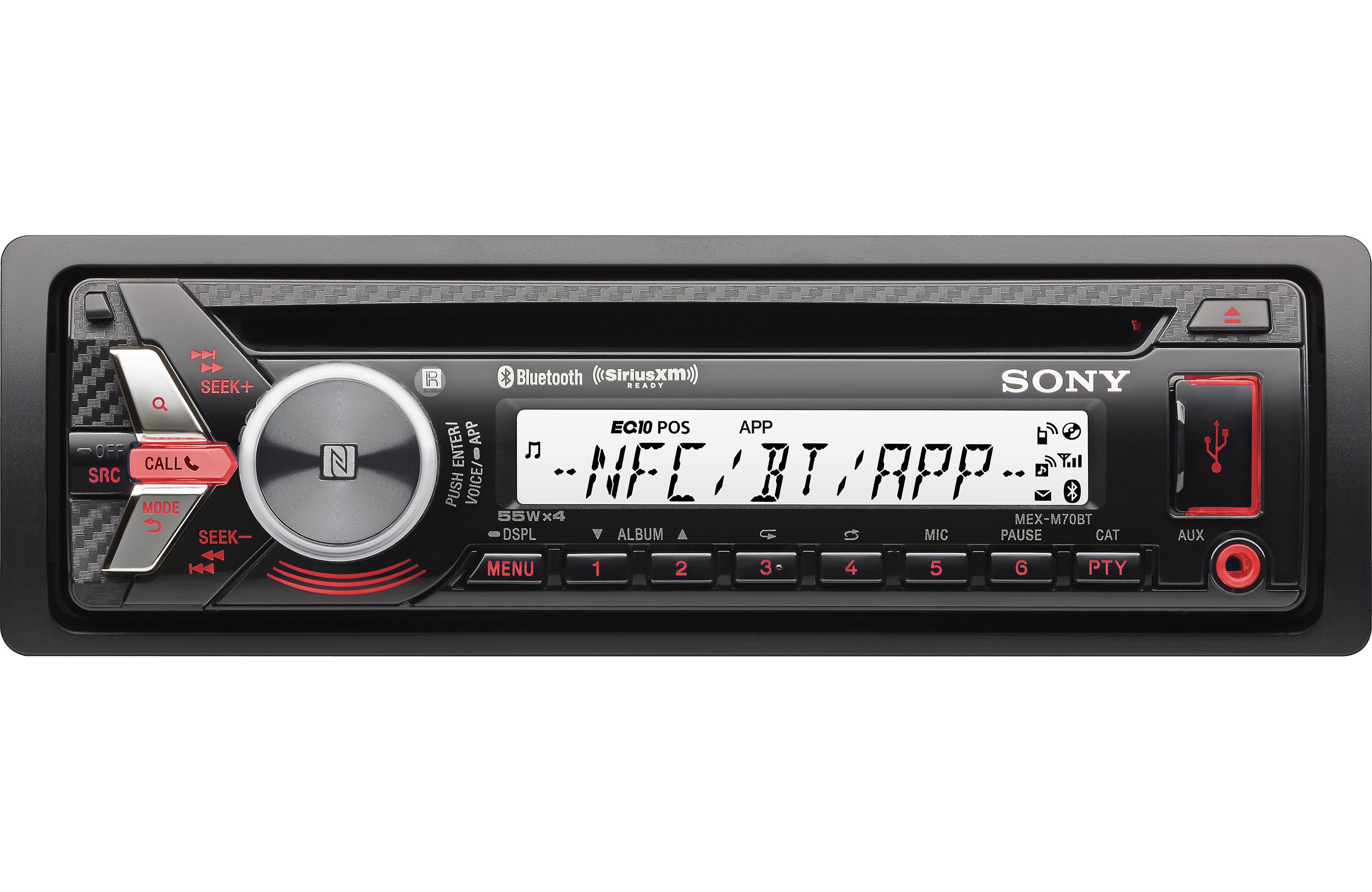 |
| Sony MEX-M70BT |
I started down this audio journey for Oliver, the MGB, simply: I wanted sound. I recognized that seeing the little LED screen when I had the top down would be difficult, so I found a stereo suited more for a boat than a car. I figured that a boat had similar issues as a convertible: moisture and glare.
I settled on a Sony MEX-M70BT, where the BT stands for BlueTooth. This plays CD's, has a microphone for hands-free phone calls, had 2 USB's for other playthings, etc. Based on the details at Crutchfield (
product link here), it has an estimated running wattage of 17 watts with a peak output of 55 watts. It delivers with pre-amp outputs (at 5 volts) and a bunch of other features that made it slightly better than or on par with the other widely available boat stereos. Car stereos have more features, and usually have greater graphics, but I intend to be driving, so I don't need a light show coming from my dash. I need easily readable print regardless of light level. The simple red or blue back-lit buttons and grey/black main panel fit perfectly with my dressed-down interior. Unlike most of the other boat stereos on the market, there were 0 complaints about product failure. None. That made the decision.
For speakers, I had an old set of Polk Audio 6x9's and 6.5" rounds. I don't remember what their peak wattage was, but it's in the 200 watt or more range. Regardless, the stereo was not going to blow them out with a wimpy 17 watts. I installed all of this stuff into Oliver in posts (
Get Sound 1 and
Get Sound 2), including mounting the 6x9's into the rear firewall and the 6.5 rounds into the foot wells.
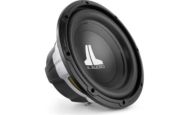 |
| JL Audio 10W0v3-4 |
With little actual testing, I did some research into which frequencies disappear when a convertible top is lowered. Similar to a boat hitting speed, the wind rips the lower frequencies away. I had expected the high frequencies to disappear, thinking that the lower frequencies would be helped regardless by simply resonating against the body of the vehicle. I had even gone so far as to start investigating small 3 inch speakers to boost the upper end when I found that Crutchfield did tests (
link here). They proved that the low end falls away. That was when I picked up a JL Audio 10W0V3-4 10 inch sub (
details from Crutchfield) to address that.
I considered the math at this point. 4 speakers each capable of handling 200 watts plus a sub capable of handing about the same, and I have a stereo pushing out pretty much 17 watts. That did not add up, so I started thinking about an amplifier.
Channels and Selection
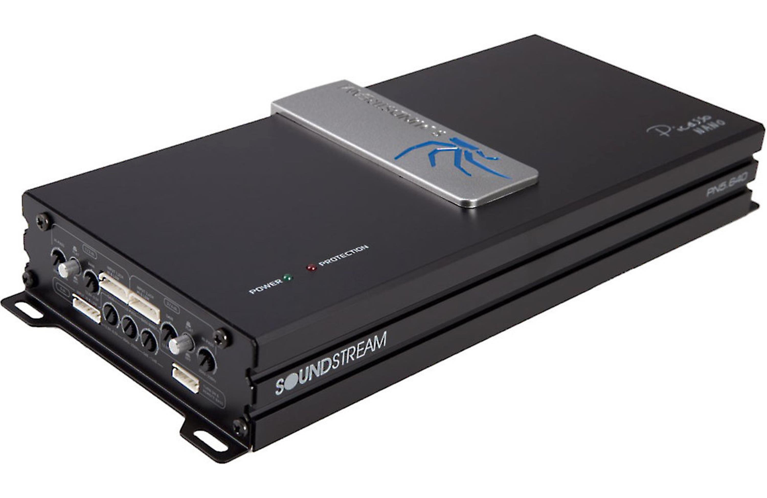 |
| Picasso Nano |
Once I made the tiny step into thinking about amplifiers, I discovered just how little I knew about it. Yes, I understood the concept, but the market and distinction between various things is fairly confusing. I considered 2 options: a single channel amplifier just for the sub woofer and a 5-channel amplifier for all of the speakers. The single channel probably would have made more sense for a system that produced more native power. 17 watts just was not going to cut it so I was probably going to need an amplifier for the regular speakers anyway, that is, if I wanted sound that wasn't totally distorted. I found
this article which helped justify my thinking and then shifted to which one, what class, etc.
Because of the tiny size of the car, I narrowed my choices down to "class D" amplifiers. Between reviews on Azn, Crutchfield and anywhere else I could get reasonable feedback (blogs, Google, etc), I settled on the Picasso Nano PN5.640 (
details from Crutchfield). This thing is tiny. It is so tiny, I can fit it inside the cockpit and hide it so the controls are within reach but it is out of sight... unless you look around for it. It sits 12 inches long by 5 inches wide by 2 inches deep (~300 x 125 x 45mm for everyone not in the US). One drawback is that it requires routing wires on both ends. I suppose it made the small footprint possible. Anyway, the inbound signals enters the front panel through 6-pin flat clips: one clip each for front / rear / sub for a total of 3. These clips can be routed through RCA cables to the pre-amp outputs or direct-wired into the speaker wire outputs from a stereo if you don't have a pre-amp.
 |
| front support from below |
Locating
First, I wanted to find a mount location that was near the occupants so the levels could be easily adjusted. Also, I had already run lengths of speaker wire from the radio head unit to the various speakers, so putting the amp near the stereo would reduce the rework there. Last, I had some higher quality RCA cables, but they were each about a meter long so if I could use them I'd save probably $100US just in cabling.
Another consideration is human comfort. This car is small. There are not many spare inches available, especially on the driver side, so I went looking on the passenger side. With the seat adjusted so a passenger is reasonably reclined for a drive, with feet mostly extended (slight knee bend for comfort), I found that there was a reasonable amount of space under the glove box. If I crossed my ankles, so one knee was higher, there was still enough space to fit the amp without that knee bumping it. Anything more aggressive might, but this amp only adds a couple of inches... so, I chose to mount it under the glove box, off center towards the transmission tunnel.
Front Support
 |
| rear support with mock |
To hold the end nearest the engine up, I re-used two bolts that pass through from the engine compartment. I test fit with cardboard templates or mocks for the amplifier and then for the supports I needed to make. I found a piece of flashing and shaped it to fit around the oil pressure hard line, fit the 2 bolts from above and have 2 small bolt holes for the "rear" panel of the amplifier. The 2 bolts required (as usual in this car) fine-thread nuts. I grabbed a pair of washers while I was at the hardware store getting that pair of nuts.
To mount the amp to the support, I threaded a pair of cabinet pull bolts through the support from above and then tightened nuts tightly against it. I passed the bolts through the "rear" slots on the amplifier and passed another pair of nuts onto the bolts. I intend to leave the support attached to the amplifier for any future maintenance, choosing instead to remove the nuts from the re-used engine compartment bolts instead, if I can. They are much easier to get to, and will need to come off when one of those bolts needs to come out for under bonnet service work around the sub-systems they were originally installed to support.
Rear Support
 |
| rear support from below |
Holding the rear end or amp "front" is more of a patch-together solution than I'd intended. I removed the glove box and mapped out a plan that involved strips of steel mounted to the crossbar that runs under the glove box. I guess, ultimately, that is what I built. Reference the picture to the right and above. I started with 2 small angle supports and a pair of steel straps with holes in them. I marked off where I wanted the supports, using the cardboard amplifier model, and then drilled holes through from below. From above, I dropped 2 more cabinet pull bolts, but longer ones. Yes, I do have a lot of those bolts. I threaded on the one-bolt-per-side angles from below and then torqued down a nut per side. I took the 3-inch-long steel straps and bent the last inch 90* and attached one 2-inch end to each angle I had just bolted on. Last, I suspended another (you guessed it) cabinet pull bolt through the one hole in the 1-inch side of the bend strapping. I threaded on a nut and torqued it down. I then threaded on another pair of nuts, and then attached the "front" of the amp before adding a final pair of nuts. Why so many nuts this time? The extra pair of nuts allows for the "front" of the amp to adjust slightly up and down. Any more significant adjustment would be handled by shifting the straps up or down. This combination created a fair amount of adjustment.
 |
| rough install lit with flash |
I left it like this and took a test drive. No, it wasn't hooked up. In fact, you can see from the picture to the right that I did not even bother to put the face plate back on the radio. This was the best test I could think of for making sure the amplifier mounting was viable. It held tightly; did not budge at all. Next, I climbed in to see how it felt to a passenger. While I'm not the biggest guy in the room, I am about the same size as my wife, who will be occupying that seat most. So, if it was okay for me, it would be okay for her. Check. Last, I asked Boo to come take a seat. She didn't even notice it until I pointed it out. She had to twist her neck a little bit to make out the knobs, so I think the location is perfect. Of course, there is not room for K2 to put his 40# backpack at his feet, but there really wasn't room for that backpack before. That will just need to ride in the trunk when he rides with me.
Like always, this got long, so I'll continue it next time with wiring and test firing. Thanks, as always, for following along-


