Continuing the process of back-documenting what I did to put a TDI engine into an old (1972) air-cooled VW bus. Today I cover what I call the "secondary electrical". This includes everything that isn't responsible for the alternator:battery:starter system. So, this is the radiator fans, the accelerator pedal, the OBD-II plug by the driver seat and any other miscellaneous stuff I can think of.
This is the first post following the announcement of
Neil Peart's death, and I can't let it pass without expressing my heart-felt loss. I love Rush and wish Getty and Alex my deepest condolences. With
2112 blasting in my ears, and "
with hungry mind and open eyes"... we return to the TDI retrospective.
Random Cables
Beyond the core primary cables, there are a few thicker wires that need to be run between the relay bank and the battery-top fuses. For these, I found wire of the same thickness, and ran them through the hole in the spare tire well, along the top of the rear engine hatch to the battery-top fuse box. This pathway became fairly well used for sending wiring from the computer to the sensors and senders around the engine. To enable that, I expanded the hole from a tiny drip opening to a 1 inch by 2 inch rectangle.
Cooling Fans Circuit
 |
| old NB pedal on left, brake switch on right |
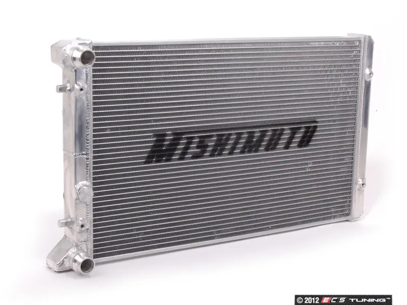
I had originally tried to re-use the TDI-stock thick relay and control module to control the radiator fans. That was a mess, and didn't work, so I ripped it all out. Instead, I used one of the small battery-top fused circuits for a power source and a switch on the dash to trigger the fans. The switch went into a hole in the metal dashboard that had not been exposed through the vinyl cover, right next to the ashtray. It receives power from an always-on source so I can cool the radiator even when the engine is off. It triggers a standard relay mounted next to the radiator on the passenger side. When triggered, the 12V from the battery-top fused circuit sends 12V to the radiator fans and the little fan on the inter-cooler. This is a simple circuit, but I have found that long bumpy road trips cause the clips to slowly shake off the relay. So, I may need to put a dab of threadlock on there to stop that.
Accelerator Pedal
 |
| new pedal |
I originally used the accelerator pedal from the NewBeetle (NB). This was a one-year-only part, so when it eventually failed I had to either pay a few hundred dollars for a replacement or swap it out for the more common pedal. The challenge with the more common pedal was that the rheostat was integrated into the pedal body, so I couldn't hide it like I had hidden the NB pedal. The NB pedal had been stowed inside the belly pan, and allowed me to continue to use the original bus pedal. The integrated housing style pedal meant that the entire pedal would be changed, and it would need a support. I still don't like the final look, but it places the pedal in the right spot for my foot, and it drives correctly. The wiring was fairly easy. There are 6 wires attached to a flat pigtail. I extended the wires and ran the 6-wire bundle under the bus from front-to-back, arriving in the spare tire well, and wired into the computer where the pedal originally wired in. I believe I used wires that were just a bit too thin, because I get sporadic limp-mode issues from lack of signal from the accelerator pedal. See
Pedal on the Right for details on the install.
Brake Pedal
NOT USED. If you intend to use cruise control, the computer needs to know when the brake pedal has been depressed. I thought about tying into the brake warning system or putting the sensor on the master cylinder. Ultimately, I made a little bracket on the arm of the brake pedal and the switch triggers when I step on the brake. I don't use cruise control, so I've kind of forgotten about this pedal. 10 years later, this may not work at all, so be advised, this may not be a viable solution. You can see a picture of my switch above. No, it isn't pretty, but at the time it was functional.
Fuel Level
NOT DONE. The range of allowed values for the fuel level gauge in the bus is quite different from the range for the TDI. If you want to swap out the original sender, I found one that would work at Summit Racing. I had thought about building a circuit which would translate the reading on the stock sender into the range accepted by the TDI computer, but I shifted onto other things. My thought was that the original gauge could still work, or I could reference what the computer thinks. I may still do this, or just buy something that does it, like the
SN34 from Classic Instruments. For now, I am using the stock level sender and gauge; the computer has no idea how much fuel we have. Most of the time, I don't either.
Speed Sensor
NOT DONE. There are a few ways to go after this. I started down a few paths and decided that I didn't need for the computer to know how fast I was going, so I stopped working on it. My first stop was to try to adapt the vehicle speed sensor (VSS) from the TDI. I couldn't figure that out. So, then I looked into getting something that fit between the dash and the speedometer cable. This looks especially promising as there is a company in Britain (RJ Engineered Solutions, VSS link
here) that makes a thread-in plug that fits into the back of the speedometer that the cable threads into. It produces a square wave the computer can understand. While writing this post, I ordered one so I could complete the experiment later. I'll post about my findings once I have some. Since I first investigated this, there are more plug-in options (like
Dakota Digital), so you may find something that better suits your project than the RJES solution. The last option is to build your own Hall Effect (or other) sensor. Whichever way you go, Dakota Digital also offers a small magic box (
SGI-5E Universal Signal Interface Unit) that can adjust the signal from the sensor to the ECU so you can account for a signal mismatch or simply because you got bigger tires... like I did.
OBD-II
 |
| UltraGauge |
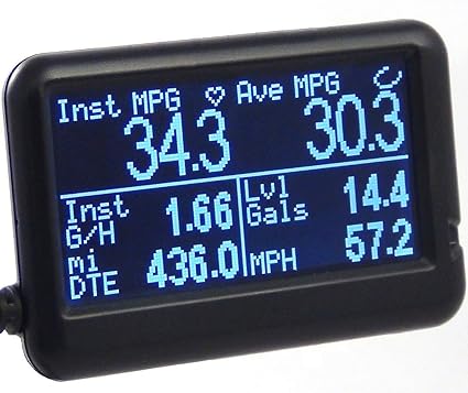
Since I decided against retrofitting the Beetle dash-pod into the dash of the bus, I still needed some engine monitoring. The old bus had 2 lights for monitoring: one to tell you you're out of oil so your engine is toasted and the other to tell you your electrical is shot. Ultimately, your warning system is your ears. Good thing the radio is so lousy, or not there, so you can hear the clamor from the engine bay. That model doesn't work for the TDI: you can't hear a coolant leak or overheating, and by the time you hear the result of the failure, it's too late. So, I extended the signal wire from the OBD-II plug from the rear of the bus to the front by the gearshift. I got a generic OBD-II plug off eBay (it's new, I just avoid Azn) that only had 3 wires: 12V power, ground and signal. The first 2 were easy, wired the 12V to a switched circuit (15) and grounded against the dash. For the signal, I traced the signal wire on the generic and determined which wire from the stock plug matched it. I know that sounds improbable, but it totally worked. Back then, there weren't the BlueTooth OBD-II readers around today. I got a wired one (
UltraGauge) for around $80US that's about 1.5 inches tall and maybe 2.5 inches wide that I have jammed into the corner where the dash meets the driver-side A-pillar. I set the screen to show me engine temp and RPM's so I can watch the 2 things I care most about. I love/hate that thing. The longer I go without a coolant temperature issue, the more I realize just how much that $80 gadget saved my engine.
Along the way, I got a
ScanTool OBDLink LX thinking I would integrate a more sophisticated graphical dashboard. It is pretty clever, and with a small tablet, a fuller engine monitoring capability is there for the taking. For me, it doesn't make sense until I have the fuel level and speed getting sent to the computer, so the tablet dash will wait.
Heater Fan
I had heat, but when I had my ignition fire, I removed the electrical parts to reduce the load on the circuits up front. If you intend to wire fans for heat, I suggest you find a strong source of 12V power and use an isolated circuit for it. I would just check the power draw for your fans and plan accordingly. You don't want to blow an important fuse because you kicked the fans onto high. I know I will be doing something to restore a defroster at least. I will probably source power from the battery-top fuses rather than the original bus fuse box and then use a new switch rather than the original Vanagon rear-seat heater switch. Because I already have it in-hand, I will probably re-use the Vanagon rear-seat heater unit, though. I'll just need to figure out where to locate it closer to the front of the bus without appearing in the passenger compartment.
Un-Rat-Nest Wiring
I have done this a few times and still need to do more. Unlike all of the other things on this project, this one is most like cleaning your shop or going to the dentist: you never feel like it, but you're so grateful you did afterwards. The original harnesses are not length-appropriate for this application. Along the way, we extended the ones we needed to extend. This step is about shortening all the others so you don't have a big old rat's nest of wire. I have sourced a relay block to re-route all of the relays, and I will be mounting the TDI fusebox as well as tidying up the wiring so it looks like it was all done on purpose. As of now, however, I have only removed the extra wires that were not needed.
There are quite a few wires running from the engine or computer to the front of the bus, but they can be isolated into clumps based on purpose. Accelerator pedal (6), brake pedal (2), ignition (2), OBD-II (1) and the fan switch (1)... so 12 wires. All of them are relatively thin, like 18ga or smaller, because they just send signals, and don't push power. Arguably, all of them could run through one cable of multi-colored wires (like
this). If I were to start from scratch, that's probably how I would do it. In fact, I may re-do it anyway and eliminate the occasional signal loss from the accelerator pedal to ECU. If you include the speed sensor and fuel level sender, you will need more than 12 wires, so maybe something like
this instead.
Prior related posts:
Preparation
Fuel System
Physical Mounting
Vacuum System
Air, Inter-cooler and Exhaust
Primary Electrical
Cooling
Next related posts:
ECU, dashpod and Sensors


 If you look back through the blog, you will not find any posts about this. Why? Well.. truth be told, I didn't do any of these. I run the UltraGauge and that alerts me of any code being thrown, so I don't need a CEL independently. I don't run the bus when it is cold, yet, so I don't need a glow plug light yet. When I do, I will tie into the glowplug circuit to light when it is energized. That's a cheap way of getting there. Others have tied into pin 40. For the coolant level warning, I will tie directly into the 2-prong sensor in the coolant bottle. Frankly, I probably should have done that a long time ago. The charging system could be a simple relay that sends a signal when the difference between the battery posts is below 12V. Alternatively, you can create a "real" alternator light by sending switched 12V to one side of a 12V bulb and the other side to the "exciter" terminal on the alternator (labelled D+ or L). The oil pressure is actually complicated because the TDI cluster determines whether the oil pressure is low for the engine speed. If you really want an independent oil pressure message, it might be worth getting an after market gauge. I haven't decided whether I want that or not. I like the simple dash I have now, though the UltraGause does not include oil pressure. So, this is a continuing risk, for now.