Showing posts with label frontend. Show all posts

Tuesday, October 9, 2018

Drag Link and Tie Rods

At the beginning of the Summer, I had this great idea of getting the alignment done on the bus before festival/camping seasons started. I realized I hadn't posted on that odyssey, so, since I just did the last little bit of fixing, I'll cover the whole thing today.

Mis-Aligning
Like I said, I started with the simple goal of having my alignment set. I had been describing driving the bus as a "full body experience", requiring the dexterity of a kit drummer to keep it on the road and motoring along. The biggest issue has been the degree of play in the steering wheel. I figured maybe the alignment was a good place to start. These old buses have a special way of setting camber requiring a thin 36mm wrench on what is called the "eccentric bushing". This bushing is integrated into the ball joint, but off-center, allowing for the camber to adjust as you move the wrench side to side. These bushings scare off many alignment shops, which I find almost amusing. They have these fancy computers to get things dialed in perfectly, but lack a 36mm wrench. Whatever. I did find a place here locally that would do it: HM Motorsports. They are a spin-off business from the local VW dealer, so they have the VW smart-guys plus the high end computer stuff. They were able to tell me that the camber was good, but one of my tie rods was bent, so they couldn't do a full alignment without replacing it. They asked me for $400US to replace that arm. Uhh... no thanks, but they did charge me the full $90US for the alignment anyway. I guess they tried, but they probably should not have once they saw the bent arm. In fairness, I should have noticed that at some point over the last 15 years myself and not taken it to them before replacing it.

Tie Rods
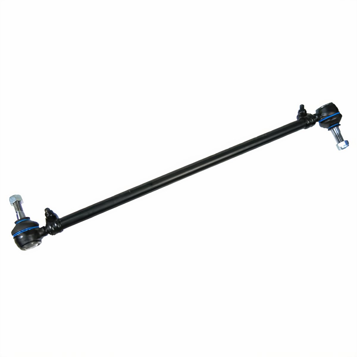
JBugs image of a tie rod
I ordered a pair of tie rods from Discount Import, and had T pick them up for me while he was there getting parts for Nemo (the A4). They charged me $35US each. The replacement was fairly easy. I started with getting the wheels as straight front-to-back as I could, centering the steering. Then, I replaced an entire arm, one at a time. The arm runs from the swing lever to the steering knuckle across the rear of the front beam. Each end of the tie rod has a 90* "end" on it that allows for controlled rotational movement. If the end can move at all any other way, it's bad. Since one of my rods was bent, I replaced the whole assembly, ends and all.

Rods Out
The ends are nutted down with castle nuts which are held in-place with cotter pins. The cotter pins may have rusted into place on yours, requiring more coaxing than mine did. Even as original parts, I was able to bend the pins back and push them out. Then the nut comes off. Last, the end needs to be separated from the knuckle or swing lever. This usually requires a pickle fork and a hammer, which will destroy the rubber boot on the tie rod end, so be sure to plan accordingly. I was able to free the tie rods by hammering away on the pickle fork. The passenger side released from the swing lever with just a couple whacks. In contrast, the driver-side steering knuckle took many many more. I have read of some needing to apply heat with a torch to get these to separate, so be prepared. Once removed, I cleaned up the holes with some WD-40 and a rag. Then, I scrubbed them with some sandpaper to make sure there weren't any sharp edges left around the holes from my removal efforts.

Rods In
Nicked from Interweb,
shows swing-lever end
and steering dampener
Oftentimes, the supplier will sell/send you two adjustable rods. This may be correct for some cars, but for the old bus, one of them is supposed to be fixed length. Discount Import only carries the adjustable rod, so the opportunity to do this wrong goes up. I followed this process for the not-bent side: measure the old rod from end to end on the top side (opposite where the threaded bolt comes out). I then adjusted the replacement arm to that same length, and then tweaked it until it dropped right into the holes. For the bent arm, this process wasn't effective. Measuring a bent arm wasn't going to get the exact length, so instead I matched it to the not-bent arm on the other side. Rather than touch the steering wheel or the tires, I adjusted the arm until it dropped into the holes. With the arms in-place, I could do a ShadeTree front alignment. Replacing the arms took less than an hour, so even at my "my free time is worth $50 an hour" rough math, I saved over $350 doing it myself versus having HM Motorsports do it.

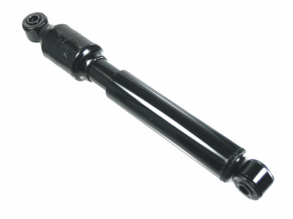
Steering Dampener
Jbugs again
Before I put in the new rods, I took the opportunity to replace the steering dampener. This is a small shock-absorber that helps cushion the driving experience at the wheel from sudden jarring affects of road hazards. Consider how much the steering wheel hops when you hit a pothole. For a car with a working front-end, it's not too bad. If your steering dampener is shot, the steering wheel gets a mind of it's own for a second. That's dangerous at any speed. In the bus, with the higher center of gravity, it's downright scary. I highly recommend replacing yours if you have no idea how old it is. I got mine when I got the tie rods for $30US. It's held on with 2 bolts (17mm, if I remember right), like a shock absorber, and it is actually pretty easy to get at when the tie rods are off.

ShadeTree Front Alignment
With the steering dampener and tie rods refreshed, I was ready to get the alignment roughed in for a test drive. All cars are a little different, so the measurement below may not work on yours, but it worked on the bus.  Measure the distance between the front-most part of your front tires (looking at the front left tire, at 9 o'clock). Now compare that to the distance between the rear-most part of your front tires. The measurement from the front should be between 0" and 1/4" smaller than the measurement from the rear. The varying length depends on your tire size; I'm running stock diameter, so this works. Ultimately, this effort should be sufficient to get you to the alignment shop. This is not an ideal permanent setting.

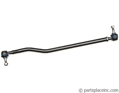
PartsPlace.com image
If you have just one adjustable tie-rod, the adjustment is more straightforward. Since I had two, I adjusted both sides one turn at a time until I hit the 1/4 inch number. Based on how the arms adjusted, I used to have no-toe or a slight toe-out. In my experience, the steering becomes less predictable with toe-out, so I'm good with a slight toe-in. I test drove the bus first slowly in the driveway, then into the dead-end street and finally around the block. The steering held much more firmly over bumps and when the street was level, and there were no bumps, it held a straight line with my hands off the wheel. There was still 3-4 inches of play at the wheel, though, when I did want to change direction.

Drag Linking
To resolve the remaining play at the wheel, I asked Boo to sit in the driver seat and turn the wheel left to right while I laid-hands on various parts of the steering system. I could see the steering coupler turn, and feel the arm move, but the drag link didn't move right away. It had a significant delay, and made a clunk noise when she changed direction from right to left (not left to right, which was weird). I rested my hands on the swing lever to see if it had any up/down movement. I couldn't feel any, so that lever and the pivot pin should be fine, unless my novice hands couldn't feel well. Other than the steering box, the swing lever was all that was left if replacing the drag link didn't fix the steering play. I resolved to replace the drag link, and bought one at Discount Import ($50US). If they had had a swing lever kit, I would have bought one since the 90 minute round trip can eat up a day if you need to do it more than once.

old drag link,
broken pickle fork
The drag link removes just like a tie-rod: pull the cotter pins, remove the castle nut, and apply force with a pickle fork to pop each end free. The drag link removes and installs from the front with the non-adjustable end pointing to the rear. I broke my pickle fork as you can see in the picture to the right. I guess the Harbor Freight fork isn't made very well.

Similar to the tie-rod, you want the replacement to be the exact same length as the old one. In the PartsPlace.com image above, you can see an adjustment lock-nut on the right end. I placed my old and new side by side to get the length correct. Take care as you pass that rear "end" through the hole in the support so you don't damage or tear the rubber boot. I left the plastic shipping cover (visible in the picture) on the end during pass-thru so it wouldn't get damaged. To get the end to fit into the swing lever, I put a socket extension onto the bolt and used that extra torque to position the bolt to easily fit onto the hole. The front end slid right in without any extra fiddling, so I knew I had the length right. If you aren't so fortunate, repeat the measure and fit steps otherwise your steering will not align properly. Last, I threaded and torqued on the nuts, inserted the cotter pins and closed up the belly pan.

Test Drive
This final test drive was quite different. The steering is genuinely responsive, with less than an inch of steering wheel movement before the bus starts changing direction. When combined with the steering dampener, it drives like a completely different vehicle. I know I should take it to have the alignment done, but honestly, I probably won't. It handles so well, holds center during acceleration and braking. Since the caster and camber were within spec before I started replacing parts, and the parts I replaced have no bearing on those settings, I may let it ride as it is.

So, Hapy is fully operational again... just in time for winter. I have plans to address rust this winter, after I complete the interior of the MGB. And, of course, there's the 280ZX that neither C nor I have given much attention to. Clearly, I have lots of content waiting to be generated.

That's it for today. Thanks, as always, for following along-

Wednesday, July 5, 2017

MGB - Front Suspension Refresh (Part 4)


This post finishes up the front end rebuild I started in Parts 1 (See MGB - Front Suspension Refresh Part 1), 2 (See MGB - Front Suspension Refresh Part 2) and 3 (See MGB - Front Suspension Refresh Part 3). At this point, the front beam is back in the car. The front shocks (and upper control arms) and lower control arms are installed with the spring pans. Today we will get the springs in, the swivels mounted and the front sway bar attached to the lower arms. By the end, the car could go back on the ground. The how-to for the springs I lightly touch on because it is pretty well documented around the internet. Not so much with the sway bar, so that's a little long.

Spring Thing
Back in Part 1, I described the concerns about how the springs were under load when the lower control arm was to be removed and that some level of care was needed to prevent it from launching across the garage. That concern returns as we approach the install. I followed the exact same routine: zip-tie the upper end of the spring to the top of the beam. Getting the zip-ties in the right spot may take a few tries with the jack (during the Jack Be Nimble step), but for now, just get the spring all the way up in the beam pocket and zip tie them so they are mostly in the right spot. Once the springs are suspended from the beam, we move on to the swivels. I did one side at a time, but I don't think there's a compelling reason to other than I confuse easily.

Swivels, bottom mount
The swivels are really nicely balanced lumps of steel, when they are mounted to the suspension. When you are holding them in your hands, or trying to attach them, however, they feel unwieldy. So, to protect yourself from, uh, yourself, put something soft under the end of the beam to catch the swivel when it inevitably topples over. It will topple. Since I had a bunch of things shipped, I took a larger flat box and filled it with the crumpled newspaper and air-filled bags that arrived with the parts. I highly recommend it. The alternative is a damaged swivel. Anyway, take the swivel for the side you're working on (caliper is on the rear), and fit the lower mount into the lower control arm. Thread the bolt from the kit from the front to the rear, minding the order of the washers (nut - washer - rear arm/bushing - swivel - front arm/bushing - washer - bolt head). Once you thread the castle nut on, you may feel driven to crank it on tight. Don't do that yet. Get is on pretty well, though; finger tight.

Jack Be Nimble
With the swivel attached at the bottom, it will want to fall over, especially when you start lifting the lower control arm with your jack. To prevent that, I looped a stretch of bailing wire around the top of the swivel and then around the shock absorber. This loosely held it upright, but didn't restrict movement. Now the fun part begins. Lift the lower control arm under the spring and set the inner edge of the spring inside the spring cup. Now, set your jack as we did in Part 1, on the outer edge of the underside of the spring cup. Slowly start raising the jack. I did it in spurts and then wiggled or rubber-mallet'd the bottom of the spring so it would shift in the spring cup. My thinking was that the cup was rotating 90* so the spring would be under weird tension as is was set into place, putting more pressure on the inner edge than the outer edge of the spring. I don't think it did much other than create more danger of the spring flying out, so consider that optional.

As I got closer to fully-installed, I found that the spring tension was greater than the weight of the car. I mean that the car started lifting off the jackstand before the top of the swivel was within an inch of the holes lining up. If you have a friend, not even a very heavy friend, have him or her sit on the wing over the wheel well. I was flying solo, so I stacked tires on the wing instead. Yes, that actually worked.

Swivels, top mount
As I alluded to in Jack Be Nimble, most of the top mount work is getting the jack positioned right, and raising the swivel while keeping the car solid on the stands. Once the holes in the upper control arm / shock absorber align with the hole in the top of the swivel, it's easy. I found that getting the top of the swivel to sit in the arms wasn't simple though. I needed to loosen the bolts that hold the top arms together a little bit so the swivel top could fit. You may need to do that same, just don't forget to torque them back down when you're firming up all of your fasteners.

Now do that again for the other side. I found that the first one took at least twice as long as the second side. Ironically, I had more spring slippage on the second side, but that didn't slow me down as much of the fear of that happening on the first side slowed me. Interesting.

Anti-Sway Bar
With the rest of the suspension put together, all that's left is the front (anti-) sway bar. In my searches around the internet, all of the articles I found about replacing the sway bar had the classic "install is the reverse". That is not helpful, so I'm documenting what I did that worked. If you're using your original bar, clean it up and paint where it's been chipped when you're doing your other parts. It is so much nicer, and the bushings go on much easier. We start with those bushings. The graphite-poly bushings are a solid trapezoid, so you will need to cut along the seam so it will wrap around the arm. I tried sliding it on from either end, including removing an arm-end, but that doesn't work. You have to cut it parallel to the path the arm would take through it.

Get the bushing onto the bar. This can be hard, but with some window cleaner (or plain water) as a lubricant, and a little force, it pops on. Use the little locks on the bar as a guide for where they should be located (just to the outside of the lock/clamp). Now test fit the bar with the new brackets. For the MG, there are 2 small black pieces of steel that hold an air deflector that need to fit between the bracket and the frame. Just test fit that it will roughly fit and that the bar is pointing the right way (ends pointing rearward).

With the brackets now removed you're ready to start the install for real. Hold the bar in the rough spot where it was during the test fit and wiggle one end of the bar into the lower control arm. Since nothing is preventing complete movement, this should be relatively easy. If the sway bar end is not making it through the hole no matter what you do, you could be experiencing a manufacturing defect in the arm. I had this happen: the rearward hole was too small for the sway rm end to pass through. I had to widen it with a drill.

Once the first one is through both holes so a bunch of threading can be seen/felt on the rear side of the control arm, switch to the other side. You may need to work kind of hard to get the second side in. I did. Lots of pulling and pushing before the bolt passed through both holes. Set the ends all the way in with a couple of whacks with a hammer. Place on the lack-washer and the 3/4" nut, but don't tighten it all the way down. Now shift to the brackets, the metal thing, and the bushings. Thread in the 2 pairs of 1/2" bolts, but again, don't tighten. Now, push/pull on the bar left and right to makes sure it is centered and there isn't any torque holding it out of center. Now, tighten the bolts and nuts down. Again, I recommend new fasteners.

Now, we can lower the car. I set the jack under the rear edge of the front beam, lift the car just enough to get the stands out and set the car down. After so many months of the front being in the air, it really looks kind of weird. Really low. For fun, I jumped up and down on the front bumper. Where there used to be considerable bouncing both on the initial jump, but in aftershocks as well... the MG barely responded to my jump and didn't bounce. It just returned to it's ride height. So tight. Once I get back on the road, it is going to hold the road like a brand new (or better) MGB.

That's it for today. This has been an incredible marathon, but feeling the difference bouncing on the front bumper tells what it will be worth. The front end should be in solid operating shape for another 40 years. Thanks, as always, for following along. I will get the festival review, the bus improvements, another road story, etc. posted as I can get to finishing the stories.

Tuesday, June 20, 2017

MGB - Front Suspension Refresh (Part 3)

I'm continuing the front end rebuild I started in Parts 1 (See MGB - Front Suspension Refresh Part 1) and 2 (See MGB - Front Suspension Refresh Part 2). At this point, the front beam is stripped and removed from the car. We've evaluated the parts, and made determinations about which to keep and which to replace. Today starts the work of putting it all back together again. WooHoo!

Pivot on the Swivels
There some things really are best left to a shop. I want to do as much as I possibly can myself, but it's not a religion. It's just a strong preference because I want to learn and because I find it fun. I read through the process for removing and replacing the king pins and bushings within the swivels (wheel assemblies). This requires a shop press, which I don't have nor do I have the space for, and a trained eye for determining the viability of the wheel assembly as a whole. So, I contracted the fine folks at British Auto Works to do it. Like so many things, I expanded the job from just swapping the king pins and bushings to also include replacing and grease-packing the wheel bearings. Doing the wheel bearings didn't really increase the cost, and it gave me the peace of mind that the entire front end had been updated. British Auto Works completely strips, and then chem-tanks all of the wheel assembly. after testing and measuring everything, they assemble the wheel and finishes the job with fresh paint. All told, it took them three days, and most of that was because they wanted extra time in the chem-tank. The finished product looks fantastic and delivered that piece-of-mind that they were properly done.

Paint
While the swivels were at British Auto Works, I started working on the beam. For being exposed to the elements, and road debris for almost 40 years, I would have expected more damage or rust. In truth, it was in pretty good shape. So, I cleaned it up, first with a power washer, then by hand with Simple Green. Once cleaned, I could see a few scratches, but it was in really fine shape. I threaded the rusty old bolts which held the front shocks back in. I did that so paint wouldn't gum up the threads. Then I sanded it, wiped it down with mineral spirits and shot it with high-gloss black paint. Since I had the time, I let the paint cure for a week, light sanded it, wiped it down and shot another coat. At this point, I removed the old shock bolts so the paint would cure without them. While I had the materials out, I cleaned up the spring pans and springs, sanded and painted them too. Truth be told, I had lots of other parts around that I intend to re-install, so I cleaned them up, sanded, wiped and shot them too. I'll share some of the tear-down and re-assembly of those things in other posts. Everything got high-gloss black except the springs. Those I shot burnt orange which from afar looks like the vermilion on the body, but its not an exact match. I decided it wasn't a deal-breaker so I also sanded, wiped and shot the underside of the frame where the front beam mounts to it. I figured I wouldn't have that exposed again any time soon so why not?

Beam Me Up
Once the paint has been shot and cured, I was able to start assembling things. First, was the re-install of the bare beam. Since I was working on this by myself, this was a great deal harder than the removal. Why? The beam is held on with 4 bolts. Each bolt has a nut on both ends, and it passes through 2 poly/graphite (or rubber of simply poly) bushings, one on either side of the beam. The drawing on the side, here, with parts labelled 1 through 7 show the front bolt. The rear is similar. Note the orientation of the bolt in the drawing: the lump is on the bottom. This is important since the thinner stretch of the bolt runs up into the frame. If you try to send the lump up, it will not make it through the frame. Yes, I did try it that way. If you're doing this on your own, I fumbled my way into a process that works:

Get the beam onto your jack, and roll it under your front bumper. Looking from above, roughly align the rear of the beam with the rear frame holes, but still a few inches below it.
Pick a side. It doesn't matter which. Take the shorter, rear bolt, and load the bolt, stacking from the bottom: nut, plate, bushing. twist the nut onto the bolt a few turns. Slide the bolt up through the rear hole from the bottom of the beam, placing the top bushing onto the bolt. I found that these bushings sort of held the bolt in place.

With the bolt held in with friction, get more precise with your alignment, but just worry about that one hole and bolt. Raise the jack and re-check. Repeat until you have the bolt and hole lined up. Then, while holding the bolt to the beam, raise the jack, pressing the bolt into the frame. Once the bolt peers through the top of the frame, put the top nut on. Again, thread the nut on just a few turns so the bolt can hold the beam, but there is still a couple of inches between the top of the beam and the bottom of the frame.
The one bolt creates a pivot point so you can align another hole. I did the other rear bolt, following the same routine. With the rear bolts loosely in, the fronts are much easier. Stack the front bolts again from the bottom: nut, plate and bushing. Set the upper bushing, and set the bolt through the frame hole. Thread on the top bolt.
Now you can start tightening the nuts. On all 8 nuts you want some threads to peek out from the nut. If you don't see threads, you may not have enough bite on the nut to withstand the pressures during intense driving. Then, torque to spec (54 to 56 ft/lbs).

Shock Me
Once I had the beam in, I shifted to installing the front shocks. If you remember, the removal was only difficult for the rear bolts because of how close they are to the wheel well. The install is also challenged by this. If you painted your beam, did you paint with the bolts out? I accidentally left one out: the one I took to the hardware store. That bolt hole was a real pain to get a bolt into at this stage. The others just took a little windex on the bolt, and it threaded right in. Once finger tight, it doesn't take much to torque it down... except getting a torque wrench in there is impossible. You'll need to feel it, as you're aiming for 43 to 45 ft/lbs. I actually came back and torqued after I did the lower control arms because the torque settings are so close, I got a good feel for what 45ft/lbs is supposed to feel like.

Lower Control Arm
Now for the fun part. Whether you bought new arms or cleaned up your originals, there are two different arm shapes: one for the rear and one for the front. The "front" has a hole specifically for the sway bar that's reinforced. Pick a side. Grab a spring pan, three sets of spring pan fasteners (1/2" nut-washer-bolt combinations) and your lower control arm bushings. If you got the fender washers like I did, grab them too. You don't need the lower trunnion kit nor the spring yet. On each arm, press in the bushing. If you got the poly bushings, this may require a press. The rubber and poly/graphite fit in without much difficulty.

Slide a fender washer onto each front-back side of the pivot (the thing on the beam that the lower arms attach to). Then fit the rear and front arms on that same side, making sure to have them pointing towards each other and making sure you're using a front and a rear arm in the right spots (rear on rear, front on front). Yeah, that sounds obvious and all, but once you get on the ground all those arms start to look the same. Consider that the flat side on the arm faces the pan (see the picture).

Let the arms hang down and grab the spring pan and one set of fasteners. Holding the pan with the dish facing towards you, lightly thread the bolt through from the outside of the arm through to the pan. Set a washer on the bolt and then finger a nut onto the bolt. Do not tighten yet. Do the other 2 fastener set the same way: 2 on the rear, one on the front. With the spring pan loosely held to the arms, slide the other fender washers on and follow with the castle nuts. Once everything is on, but loose, start tightening things, moving from castle nuts to spring pan fasteners so no bolt gets hung up because it has been left untouched for too long. When everything is snug, torque to spec: 22 ft/lbs for the spring pan fasteners and 45 ft/lbs for the castle nuts.

For the castle nuts, align the castle with the cotter-pin hole and put in the cotter pin (or bailing wire, if you're like me). Better to torque a little too much than not enough, IMHO, but you shouldn't need to go higher than 50 ft/lbs. If you do, re-check your work. Maybe something is hanging up.

That's it for this time. I should be able to finish this up in just one more post. I'll get the swivels and springs on, and then the major efforts are completed. Thanks for following along. This has been an incredibly rewarding effort.

Tuesday, June 13, 2017

MGB - Front Suspension Refresh (Part 2)

Continuing from my last post, I'm focusing this group of posts on the rebuild of the MGB front end. Today, we get down to the beam, and get it removed from the car. I'll evaluate parts, and talk about replacement bushing options. Part I can be found here.

Shocking
While the beam is in, and you have access to your front shocks is the best time to evaluate them. On the right side, the shock responded relatively well to my efforts to move the arm up and down. It resisted in both directions, but not as much as I would have liked. Still, I probably could have left it alone. The shock on the left (driver) side, however, offered virtually no resistance to my attempts to move it. In fact, I could push it to the top of it's motion and it would slowly drop down. That shock is shot. Suspension shops usually recommend replacing both fronts and/or both rears at the same time. For a front-end like this one, where the shock absorber is also playing the part of the upper control arm, it is all the more important. These are held in place by 4 bolts. The two against the inner wheel well can be difficult to get to, but you can address them with the most basic spanners and ratchet/sockets. Similar to the engine mount replacement (see MGB - engine mounts), a good supply patience is welcomed here.

Set the shocks aside with the lower arms and pans. To protect the threaded holes, finger the old bolts back into the holes. I took one with me to Orchards and found replacement grade 8 stainless steel ones for the reassembly. I strongly recommend replacing fasteners with stainless steel or zinc coated to reduce the rusted-on effect.

Beam Down
image swiped from 'net,
but that's a stock beam
Now, the front beam should only be connected to the car by 4 bolts. Nothing else should be tying them together. No brake lines, steering bits, etc. but it never hurts to stupid-check (so-called for those moments when you don't check, something bad happens and call yourself stupid for not checking).

I used an ATV / transmission jack, but a more standard wheeled floor jack should work; it will just take more patience with balance. The ATV / transmission jack is nice in that it has two long arms to spread the weight, and improve the balance. Still, with the front end way in the air, and the rear on the ground, the bottom of the beam is not parallel to the floor. So, I slid a 2x4 under the front of the beam when the ATV / transmission jack reached the underside of the beam to make uniform contact. Raise the jack until it is holding some weight, but not much. You want the car stable on it's jack stands.

Relieve the torque on the 4 bolts by cracking the 4 bolts on top. you shouldn't need to hold the bottom nuts at all for this. I used the breaker bar with an assortment of extensions. Once cracked, do the same on the bottom nuts, just so they are not rusted in place. Whether you remove the nuts on top or the bottom or a mixture doesn't really matter. In the end, all 4 bolts need to be un-nutted on both ends. You would think that once the nuts have been removed from the bolts, they would just fall out. Fat chance. How about lowering the jack a little bit? Nope. To free the bolts, the top nut needs to be removed. Then, using a socket extension so you can address the bolt, rap the bolt from above with a rubber mallet. When this doesn't work, use a framing hammer, but be very careful with those bolts. They are not normal and if the threads are damaged, you'll need to order new ones.

Once the bolts fall out, either through banging or playing with your jack or maybe you got lucky and they just fell out... you'll see that these bolts are 2 different lengths and that the longer bolts (that fell out of the front) have a lump in the middle like a poorly rolled spliff. I retained all of this hardware, choosing to not try to find replacements, though I thought about it. Simply lower the jack, and the beam will lower with it. Pull out the front under the radiator and bumper.

Parts and More Parts
At this point, I was pretty spent. From the start of the prior posting to the beam on the ground was at least 2 days. Now that I've done it once, though, I could do it again in 1/3 of the time or faster. As I set with a beer, I looked at the pile of parts and the zip-lock baggies of fasteners. The fasteners were all bare steel, and they had plenty of rust on them. I chose to replace all of them except the beam-to-frame nuts and bolts. I added 4 fender washers to fit between the beam and the lower control arms. I felt this would help the bushings last longer. The fasteners probably put me back $50. Then, I turned to the pile of parts:

front shock absorber /
upper control arm
Front Shock Absorbers (2) New, these are crazy expensive. Moss has them for over $330 each. Instead, I found World Wide Auto Parts in Madison, WI who rebuilds originals. After some research I bought a pair from them at $99 each plus core which was returned when I sent my old ones back to them. They really look great, and if they work as well as they look, I just may go back for replacements of the rears instead of doing the swap-out for non-MGB rear shocks that so many folks do. The paint chips off without much effort, so if you're going for a show-car experience, I'd recommend repainting them.

Lower Control Arms (4) These looked okay, but without tight tolerance measuring tools, I couldn't tell if any of the important holes on the ends were out of round. Replacements for all 4 was $70 with OEM British steel, and the originals could have been worn from the bad seals, so I coughed up the $70.

lower control arms
Spring Pans (2) Like the arms, I couldn't tell for sure if the mounting holes were out of round, but on very close examination none of the holes looked oval. Since no pivoting happens with these pan holes, even a little out of round probably wouldn't matter so I chose to keep the spring pans, and just clean them up instead. New-steel replacements are $32 each at Moss, so they're a little steep cost-wise compared to some of the other bits. Still, if the spring pan won't firmly attach to the arms, your suspension won't be safe, so spend the $64. In the end, there was 0 play after everything was put back together, so my assessment was correct.

Front End Rebuild Kit (1) This was the whole point of this work. I found a few different suppliers for this kit, and resolved to buy from British Parts Northwest for $120. While their return policy is crap, their price is $35 less than Moss. These kits include:
- king-pin set and bushings. These run vertically between the arms and through your swivels
- upper control arm nut/bolts. They call them "fulcrum pin and hardware" and they attach the top of the swivel to the control arm / front shock absorber.
- upper control arm bushings (rubber or all-poly). These pair with the upper control arm nut/bolts to complete the set. I ended up swapping out the kit-supplied ones with some Poly/Graphite bushings I got from a new friend, Basil, in California ($6)

- lower control arm to swivel bolt/nut and bushings. They call these "Lower Trunnion Kits".
- lower control arm to beam ("A-Arm") bushings and bolts (rubber or all-poly). Again, I went with Poly/Graphite ($20) from Basil instead of the kit-supplied ones.

To do the front end rebuild, that's really all you need. I decided, though, that as long as its open, replace the beam-to-frame bushings.... and the sway bar bushings. Again, I sourced these from my friend in California. frame bushings ran $23 and the sway bar bushes were $10. When I consider there was no extra labor for the beam bushings, and very little on the sway bars, this was a very low cost to get the front end as rock-solid stable as possible.

Rubber, Poly and Poly/Graphite
Just for an aside, I wanted to touch on the differences between these three types of bushing. As a general rule, it's best that you pick one and stick with it through the front end. Since they behave a little differently from each other, the front end could be less predictable if your lowers and uppers are not the same material and respond to stresses differently.

Rubber - this is what you had originally. When squeezed between two pieces of steel which want to twist, the rubber twists with it. This smooths out the twisting motion, giving an easy, forgiving ride. For a cruiser, this is great material.


beam to frame bushings
Poly - this is the more common "upgraded" bushing. Unlike the rubber, the poly does not twist with the steel; it resists the twisting motion. This resistance reduces the degree of the twist, allowing more of the force through to the ride. This is a much less forgiving ride, but gives you a much stronger "sense of the road". Installing these bushings can be very difficult, requiring water-based lube or other tricks, maybe the use of a shop press. Once installed, most owners report loving them.

Poly/Graphite - this is in-between the Poly and Rubber in terms of road feel and difficulty of install. Basil described this far better than I could, so I will quote: They look like black plastic that has some give to them. You can put one between your thumb and forefinger and feel it give a little. The polyurethane matrix has a slippery substance called "graphite" (a crystalline form of carbon) in the polymer matrix so a slippery bit is always exposed and thus self-lubricating the bushing. No special install efforts needed.

This post got long again, so I'll continue in another post. At this point, we have the front beam completely torn down, our parts are ordered, and fasteners sourced at the local hardware store. We'll start next time with some painting and then assembly. Thanks, as always, for following along...

Tuesday, June 6, 2017

MGB - Front Suspension Refresh (Part 1)

Before I took the little British car to a shop for review, I did the brakes on all 4 corners (See MGB - Brake Job). While I had the front end on jack stands, I noticed some weirdness with the front end suspension. Today's post starts the documenting of that work.

Well, That's Not Right
weather stripping?
So, I had the front end in the air and the front wheels off, trying to get after the bolts which hold the calipers onto the front swivels. On my back, lying under the front right (passenger) fender, or wing in British car parlance, I noticed that the front of lower control arm was attached to the front beam, but it looked like the bushing had been replaced with a strip of window insulation. Huh? I pushed and pulled up and down on the arm and it wiggled. Yikes. I looked at the point where the front shock attached to the top of the swivel, and that bushing looked old and tired: brittle and cracked. The top connection didn't wiggle, but something that brittle was at end-of-life. I slid around to the left (driver) side. There, I found more dust and more surface rust, but both the top and bottom bushes on the swivels looked like the top of the passenger side: old, brittle and tired. This front end needed a complete re-bushing before being driven very hard.

Getting Down to the Beam
I had a few weeks between jobs around the holidays, so I thought it was a perfect window of opportunity to do the front end. I did spend some focused time during those weeks, but I also took advantage of an amazing snow season by hitting the mountain a few times, I visited with family, etc, so I didn't exactly get this done within the window. As usual, this took me longer than it would probably take most folks to do.

Since we're working on the front end, we start with loosening the lug nuts and then putting the front end on jack stands. This time, get the front end as high as you can get it without getting nervous about how high it is. The key here is having it high enough so the lower control arms can hang straight down once disconnected. Figure, that's at least 16 inches at the rear of the lower control arm. Once on the stands, remove the wheels and stow them out of your way.

Disconnect the brakes. Start with loosening and then removing the calipers. You may need to pull the pads before the calipers will come free. I was able to remove everything as a unit but I just did these pads. I ultimately needed to disconnect the front brake lines so I'd suggest you completely remove the calipers from the car now. Once the calipers are free, disconnect the brake hard-line from the front beam. Remember that brake fluid is corrosive, so wear gloves, use a catch-pan and dispose of safely. Its nasty stuff on your paint too, so basically, have it avoid everything but the pan.
get it way up in the air

Remove the steering rack. I already had mine off (See MGB - Steering Rack), which was one reason why I jumped into this over the winter.

Disconnect the front sway bar from the control arms. In the picture above, you can see them still connected to the lower control arms out near the wheels. Once the nut is removed on each end, coax the threaded end out the front. Sounds easy, and the second side is. The first side can be a bear.

Orienting on the Lower Control Arms
If you have ideas about doing more than just replacing the beam-to-frame mounting rubber, there's more to do. If not, I get to dropping the beam in my next post. Since I aim to refresh the whole front end, I kept going.

First, pick a side. If you are space-constrained like I usually am, pick the side where you have more room first so you get a feel for the work and don't lose your patience as quickly. If you consider the lower control arm is a capital "V" lying on its face, there are 2 bolts holding it on: one at the bottom and one across the top. The one at the bottom attaches the arms to the wheel assembly (often referred to as the swivel). The one at the top attaches them to the front beam. Extending our capital letter metaphor, the spring comes from above and lands into the middle of that "V", making it more of an "A". Where the spring reaches the arm there is a round cup for the spring to sit in. It is not held in place by any fasteners; this last bit is an important safety consideration during removal.

Pop Goes the Front Spring
bottom of the "V"
Start with putting your floor jack under the spring cup in the lower control arm. Set it far enough to the outside where it will grab the cup edge but not so far out that you can't get a spanner or socket onto the bolt/nut because the jack is in the way. Raise the jack just enough to take some of the energy out of the springs. There is a debate on the internet about how pressurized these springs are and whether there is reason for concern for them launching when the arm is removed. They are under reasonable pressure and there is reason for concern. Take a couple of zip-ties and zip-tie the top of the spring to the beam. If you don't, it will take off in an unpredictable direction when the lower arm is lowered.

Back to the removal... there is a cotter pin running through the castle nut, so remove that. Take note that replacement cotter pins are NOT included in any of the rebuild kits available out there, so either get some independently or do like I did and use bailing wire at install-time. Crack, loosen and then remove the nut/bolt that runs across the bottom of the "V" I described above in Orienting on the Lower Control Arms. The bolt can be hard to remove. Unlike the cotter pins, replacement castle nuts are included in the kit so you can use your old castle nut on the end of the bolt as a target for your hammer. The castle nut doesn't take punishment as well as a standard nut, so you still need to be careful: once the bolt breaks free, you still need to be able to thread the castle nut off the bolt to get it completely out. With the bolt out, the jack is all that is holding the spring under pressure. Make sure the top is zip-tied to the front beam! Slowly lower the arm until the spring pops out of the cup. If you raised the car high enough, you will be able to completely lower the jack and the arm will hang straight down. Sometimes the swivel gets hung up in the arm, so you may need to coax the 2 pieces apart. If you find this necessary, be mindful of how much spring tension is supported by the jack. It will unload quickly if not contained by the jack.

Once the arm is hanging free, cut the zip-ties and move the spring out of the way. You may choose to paint or powder coat them as long a they're out. I shot mine with paint, thinking I didn't have time (nor money, the paint was free leftover in my cabinet) to powder coat.

Spring Pan
Removing the rest of the arm assembly isn't terribly difficult, even for me. The spring pan is held to the arm with 3 nut:bolt combinations. If I remember correctly, they are all 1/2" drive. There are two on the rear and one facing front. The front one was paired with a threaded end of the sway bar which we removed earlier. With the bolt:nut combinations removed, the arms and spring pan should fall to pieces. Set the spring pan aside.

Remove the Lower Control Arms
The inner end of the control arms are held to the front beam with large castle nuts. The nuts are held in place with cotter pins. Like the pins at the other end of the arm, these do NOT appear in any of the kits available out there, so either acquire some elsewhere (local hardware store) or use bailing wire like I did for install. So, remove the cotter pins that hold the castle nuts, then remove the nuts. There are replacement nuts and washers in the kit. Set the arms with the spring pan for inspection.

Upper Control Arm... Er.. Shocks
left swivel top
Unlike lots of other cars, these little British cars don't have a traditional upper control arm and piston-style shock absorber. Instead, the shock and upper control are are one kinda weird unit, but it works. They are oil-filled, and for space purposes, it makes the most of what's available. The top of the swivel is attached in a similar way to all of the others in this job: castle nut, cotter pin,
long-ish bolt that needs to get banged out with a hammer. The rebuild kits also provide parts the same way: all bolts, washers and nuts are provided. NO cotter pins. The swivel is kind of heavy, so put something kind of soft to catch it when you get the bolt removed. If your experience is like mine, you'll be banging away on the bolt and then without any real sign it will suddenly pop out and the swivel will topple. Without something to cushion it's fall, a drop onto the concrete of your garage could damage something.

Now, do the other side. Whee!

At this point, your lower control arms are removed, and your front swivels are as well. Your front shocks are still on the beam, and the beam is still in the car. This is when I will pick it up next time where I'll cover removing the front shocks, evaluating them, the spring pan, and control arms for re-use, buying parts and of course, lowering the front beam.

Thanks for following along. This series of posts represents one of the longest, biggest things I've done since I rebuilt the front end on the bus: the post that launched this blog.

Tuesday, May 16, 2017

MGB - steering rack

The last collection of posts have been about this project MGB I picked up last Summer/Fall. Today's post covers the efforts of removing, cleaning, and repairing the steering.

Context
The steering on these little British cars is only a hair more complicated than the old VW bus. The bus uses a system called "worm and peg", which is definitely not used in modern cars. Without opening up the steering box, consider that there is magic inside this box with two arms coming out it. The arm coming out the top connects to your steering wheel and the arm coming out the back connects to control arms that terminate at each of the front wheels. Within the magic box live the worm and peg. The "peg"  rides on the "worm" that is a threaded bar that looks like an auger. As the steering moves from lock to lock, the worm moves the peg from side to side, causing the front wheels to turn. Simple design.

3-armed monster
The MGB has a rack and pinion style. Rack and pinion has a gear (pinion) at the end of the steering column that rides on a "rack". The rack is simply a toothed bar to which the control arms are attached. In the case of the MG, the control arms and the rack are all one piece. Power steering includes more bits to boost the power of the pinion to move the rack. The MGB doesn't have the power assist, but its a tiny car with little weight, so there isn't much need. One other interesting bit about the MGB steering is that over half of the steering column is part of the steering rack so it has 3 long legs/arms to manage on extract and install.

Getting It Out
just removed. note torn d-side boot
Removing the steering rack from the MGB is actually pretty easy. For me, someone who takes forever to do even the most simple of jobs, that's a big statement. At the ends of the control arms are tapered "ends" that fit into the steering knuckles (sometimes called "swivels"). Since I had already decided to replace the rod ends, I separated the ends from the knuckles with a couple of smacks with a hammer. There are gear remover tools that are more graceful, but if you're replacing the ends and the nuts (always replace the nuts) anyway, a hammer works great.

p-side arm measured
With the ends separated from the knuckles, move up to the steering column part up near the firewall. Mark the way the two ends come together so your steering wheel will align properly on your first re-install effort. I shot the joint with a pop of spraypaint, but that was only because I couldn't find something like a paint pen. You can just see the marks in the picture on the right, here. Once marked, loosen the connection so it doesn't hang up on you later.

In order to easily get to the rack bolts, you may need to remove the little section of cowling between the radiator and the front beam. It is made of glueboard and held on with a couple of nuts. There are metal replacements for the cowling available, if your original is trashed. Once you have access to the rack, it is held on with 4 long-ish bolts. With those bolts removed, the rack can be removed by pulling it forward and down. If it isn't budging, check that the steering column is loosened enough.

Cleaning
p-side arm measurement
My rack was leaking, and was identified as a possible replace item by the shop. K2 and I saw that the bellows on one side were definitely torn, so I ordered a replacement set as well as replacement arm ends. We (step-son K2 helped a bunch here) started with simply cleaning everything up first. K2 used "Simple Green" and a lot of elbow grease to get the arms and main cylinder clean.  You can't put new bellows on while the arm ends are still attached, so when it was clean, I marked the control arm end positions with a shot of spraypaint (use a paint pen if you have one). Once marked, I removed the arm ends, and then the bellows. At this point, K2 doubled down on cleaning. He turned the steering from post to post, cleaning up any gunk that he found in the teeth. We removed the cover plate and looked for broken teeth on the pinion as well.

Repairing
Junk. Don't Buy These
The pinion had no broken teeth and the arms were in great shape. We decided not to replace the steering rack, and just re-seal the cover, refill with oil and replace the bellows. I used a very light application of form-a-gasket to help seal the cover. If you use too much, it gets into the gears, and that detail cleaning needs to be redone (guess how I know that). Before the cover plate is sealed on, the bellows need to be put on. Put a little bit of gear oil on the inside edge of the small end before you start. This allows the small end to slide over the end of the arm without tearing. Attach the wide end to the main cylinder and a-fix with the metal band. Before attaching the small ends, check where they should go so that they don't stretch nor bind when the rack is turned lock to lock. If you have marked the old location, its easy. I didn't but I found that once I started zeroing in on a spot, it actually was the same original position (there were tiny scratches on the arms). Tighten the small ends down with the smaller metal bands. Now, fill the system with gear oil: 90 weight (like the VW bus transaxle). "Fill" is about 8oz.

Ends
OEM. Buy These
Once everything above is done, all that's left are the ends. There are two kinds available out there, and I bought both to see the difference. These cars came with sealed ends that allowed no maintenance. So, if you thought your end needed grease, you can't grease it; you need to buy replacements. These replacements are made in England, though, so you're getting a good OEM part when you go this route. There are also replacements available which have a grease fitting. These are Chinese junk. The concept is great, the execution is appalling. The pair that arrived were rusty and the main rubber seal was falling off. Not only would it not hold grease, the rubber "seal" wouldn't stay on at all. I was only able to find them at the Roadster Factory, but don't shop there. When I alerted them to this poorly built part, and returned it according to their rules, I received no communication nor any money back. Vendor: if you sell garbage and then don't honor your own policy, you're a sham to me and will be called out accordingly: do not shop from The Roadster Factory unless you're willing to accept crap parts with no means of return.

Ends On
The OEM part, as expected, looked perfect and fit as you would expect. I threaded it on to the marks and tightened it down.

I am finishing up some other tasks before re-installing the rack, so I will post again when I have that completed. Thanks, as always, for following along.

Thursday, June 12, 2014

Commencement

It's been an odd couple of weeks and I apologize for not posting something.  I reference two major starts as "commencement".  The first, the beginning of a driving history after an accident and the second a post-high school life.

Alex Reiger, He's NOT
On the Tuesday after Memorial Day, T was asked to play taxicab for his brother.  C had a lacrosse game in Canby at 6, but his lacrosse equipment was in Beaverton and they both had been over-nighting at their mom's house in Lake Oswego.  This meant T had a couple of hours of driving to do in rush hour traffic, ending in the confusing street-design around Canby High School.  Not a good set-up.  They almost made it without incident, but while trying to navigate the weird streets off and around the high school and 99E, he got into a fender-bender with a local.

27 8x10 Color Glossy Pictures with Circles and Arrows and a Paragraph on the Back of Each One
The "local" was a brash and unpleasant 20-something woman driving a relatively new, but woefully uninsured Kia.  While T was found mostly at fault because he was turning left as she was trying to go straight at an intersection, the way the scene went down has me wondering if we got the full story.  Flash had his front corner on the driver's side folded in, damaging the front fender, bumper and hood.  The left-turn signal doesn't work correctly.  Her car got a dented driver's door.  T had already crossed the first of the 2 oncoming lanes and was driving quite slowly.  She accelerated into the intersection.  Did she think she was going to be able to dodge around him?  When T and C drew the scene, and played it out with matchbox cars, things didn't add up quite right.  Lesson learned here: immediately after impact, start snapping pictures with a cell phone of the damage, the intersection and parts of the cars which were not involved.

Show Me Yours, I'll Show You Mine
After the impact, both cars drove to the side to exchange information, but she had no insurance to share.  Just a phone number.  Multiple witnesses saw that and heard everyone say they were unhurt.  Yet, a couple of days later, the other driver was claiming her car was undrivable and she intended to make medical claims against our insurance.  I guess she saw an opportunity to get 6 months of free massages and a full body paint job on her car.  Multiple phone calls, phone tree navigations and conference calls later, T was assigned more than half of the blame, but not sole responsibility.  The other driver tried to get insurance after the accident and then filed a claim with them too.  Hilarious.  That was shot down, and now the insurance folks have put the sheriff onto her case for driving without insurance.  So much for those free massages; instead she gets SR22 insurance (read: more expensive) and possible license suspension.  Neat.  Then, there's the attempted fraud.  If she had realized she was driving illegally, maybe both sides could have just walked away without reporting to insurance.  Now, everyone loses.

We have had good happenings too.

K-ommencement
Yes, that's plain awful.  Sue me.  K attended a challenging high school and prioritized an after-school driving job over studying during his sophomore year, digging for himself a deep grade hole he almost couldn't climb out of.  But he did.  His junior year, he prioritized the Science Fair over all of his other work, and again, he found himself in a hole, but not one as bad as the year before, and again dug his way out.  This senior year, he again got an after-school job and through determination and focus he graduated.  Like Hollywood movies, the big ending is all the more satisfying knowing the main character had obstacles along the way, met those challenges and ended victorious.  That was the story line of K's high school career.  Greeted with loud cheers from his brother K2, mother & father, his paternal grandparents, his step-father and step-brothers, K produced a huge smile as his name was read.  He crossed the stage as if on air, and in his usual floppy way found his way back to his seat.  As the graduates left the auditorium, K skipped.

And now what's next?  He's 18 and high school graduated.  Boo and I returned home from the post-commencement brunch puzzled by that thought.  He's the first of the 4 we will see leave the nest, and he's setting a great example of how to transition into independence.

Car stuff:  I did the rotors and pads on Flash a few weeks ago, didn't apply grease nor anti-squeal goop and regretted it.  I did them again, and now they're dead quiet and stop well.  Goes to show that anti-squeal goop isn't snake-oil; it actually works.  I haven't been able to play around with the bus other than fiddling with his shifter again.  I was able to drive him to work every day last week, and that was a true pleasure.

I guess that's it for today.  Thanks for following along, and Hapy Last Day of School-

Thursday, May 15, 2014

Flash Panzer Plated

I had an unexpected gift this past weekend.  My wife, Boo, took a brief trip to the OR coast with a girlfriend, so I had Saturday to myself.  It being NHL playoff season, I caught 4 games, of course, but I also finally addressed the old Jetta, Flash, with a long-awaited Panzer plate.  I'll give a run-down on that today.

Panzer Plate?
Evolution plate
So, what's a Panzer Plate?  In the early 2000's, VW engineered a very tall diesel engine to tuck under the bonnet of the Jetta IV, Passat and New Beetle.  I say "very tall", but its really relative to the available height between the underside of the bonnet and the ground.  From the factory, the underside of the engine was shielded from the ground by a thin sheet of padded plastic.  This kept dirt and small gravel from getting up under the hood and into the engine bay, but did little to protect the engine from rocks, manhole covers and any other kind of road-borne debris that we regularly encounter.  The most exposed part of the engine, down below the front beam, is the oil pan.  Many engines have given their lives to road hazards because the hazard popped a hole in the pan and all the oil ran out before the driver knew anything was wrong.  There are aftermarket oil pans to help address this, but they don't act like a skid-plate defraying the impact along.  They are designed as a hard-edge that is simply strong enough to take a frontal impact.  I'm not convinced they can withstand the same abuse that a skid-plate can.  If they did, off-roaders would do that instead of installing skid-plates.

Which One?
DieselGeek
full metal jacket Panzer Plate
There are at least 2 skid plates available on the market, one from Evolution and one from DieselGeek.  I've heard there's a VW one made of steel, but I've never seen one.  I tried to find one via an on-line vendor, but it wasn't nearly as clear what I was looking for as, say, a rear tail light.  If VW makes one, why wasn't it part of the car in the first place?  Or, why wasn't it part of a recall once they realized it was necessary to save your engine?  Last, why are they so hard to find?  Sigh.  Anyway, I read a little about the Evolution, and it seemed as good as the Dieselgeek one except for issues stemming from the way the oil-drain hole was engineered.  There was some feedback about the support around that hole actually causing a puncture in the oil pan.  Yikes.  While that played in my mind, the need for the "full metal jacket" available from Dieselgeek was a real decider.  I had long lost the padded plastic shield and the side supports went with it.  All-in, I paid around $380.  That's painful, but killing the engine would have been 10x that cost.

So?
It was so easy.  I read the printed instructions while watching hockey Friday night and they didn't make any sense.  Re-reading with a beer didn't help, so I just pulled out the parts and made sure I had everything in the parts list.  Check.  Saturday morning, with KBOO's bluegrass show playing in the background, I drove up on the ramps and took my college try.  Once you get under the car, the instructions make sense, everything is where they describe them to be, and it all fits right together.  Even the RivNut installations were easy.  It took me less than 3 hours to get the thin aluminum sides in, the front mounting posts in and the Panzer plate on.  Before KBOO switched over from bluegrass to the Grateful Dead & Friends show, I was done.  Shazam!

Unrelated, I drove the bus to work today.  So nice sitting behind his steering wheel :)
More next time-

Monday, April 7, 2014

Film at Eleven

With the start of April comes the Pacific NorthWest's faux-Summer.  We're really experiencing that now, with mid 70's temperatures, clear blue skies and bright smiles on everyone's face.  In an ironic contrast, I spent Sunday afternoon in my sun-blasted garage solving the water-block problem both under the belly-pan and in the passenger door.  I'll hit that today.

Plastic Fantastic
from vw-resource.com
First, I need to give credit where due.  I stumbled upon this website while trying to figure out a viable way of keeping the water that makes it past the window seals from damaging the new inner door panels / cards.  The old plastic was pulled out, and the cards were destroyed.  The guys at the vw-resource web site had a great suggestion for using BlueTak on their page dedicated to the doors.  In my last post, I mentioned that I bought some of the 3M stuff that was basically the same.  I borrowed their picture on the right here.  The 3M stuff is white, so it doesn't show up as well in pictures.  I posted one here anyway.

trash-liner door-liner
Note how much less I used (I relatively uniformly used around 1/4" thickness).  That became an issue when I tried to hang visqueen.  The plastic sheeting that you get in most home remodeling shops is too slickery, and won't stick easily.  Instead, I considered what was originally in there: a very thin film.  I grabbed a kitchen garbage bag, and hung it on there instead, aligning the bag bottom with the door top and one edge against the front edge of the door .  Because of the static electricity built up in the bag, it immediately clung to the steel, making the pressing into the 3M stuff much easier.  I cut the bag in half along the front / leading edge of the door, and folded it back against the rest of the door.  Some simple trimming later, and the door is sealed.  Like the vw-resource guys, I poked holes where the rubber bits will be going and made sure to run loops of sticky-stuff around those holes.  Be sure to run loops of the sticky-stuff around the holes for the window winder, door pull and the latch.  One other thing to note, I didn't run the plastic to the very bottom of the door; only to the very bottom of the hole in the door and then put multiple runs of sticky stuff along the bottom.  Remember, the whole idea is to keep inside the water that's inside the door, so it runs out the bottom.

Bag in the Pan
exposed electricals. 3M sticky
After such a simple success with the door, I slid under the front of the bus and pulled the belly pan off. My drive-by-wire electronics are under there.  This has been a source of concern any time I go for a drive when the pavement isn't dry.  While it is really just a simple resistor attached at one end to the pedal and the other to a wiring pigtail, its still an expensive replacement.  If it got wet, it would fry, and I'd need to replace it.  As I write this, I realize that there aren't any fuses in the wires either, so if something shorted out, there could be ECU troubles.  Anyway,  in looking at the exposed electronics, I noted so many openings where water could get through: from the rear where all the controls go through, over either side of the main frame members, etc.  Yikes.

same view, but bagged now
I had thought of plastic-sheeting the entire area, but that would have been nearly impossible.  Instead, I figured I could just "bag" the electronics by running a circle of sticky along the bottom of the floor and sticking another kitchen trash-liner against it.  It totally worked.  It has a small hole for the pigtail, but otherwise, its protected from water.  Once the rainy season returns for May and June (like it always does), the bus will be road-capable.

That's it for today.  I spent Saturday watching C play in 3 lacrosse games, starting the Spring sports season.  We hoped to hit Mt. Hood on Sunday, but it was raining up there, trashing those hopes.  I'm starting to believe that the Ski Bowl season is about over, between that rain and today's warm temperatures.  I've heard it will hit the mid 70's through next weekend.  So, after an unimpressive snow season, our Spring conditions appear to be disappearing.  Time to plan camping season instead!  Thanks for following along-