Showing posts with label tie. Show all posts

Tuesday, October 30, 2018

MGB alignment

In a rare moment of peaceful reflection, I realized that when I rebuilt the front end of the MGB, I failed to perform an alignment. Today's brief post is about how to do that.

Caster, Camber and Toe
On modern cars, a front end alignment involves tweaking three different adjustments. Caster is the rotational pitch the front wheel revolves on. This is hard to put into words, but picture the front wheel on a shopping cart and how it wobbles when you get a "bad" one. Your front wheel can have the same effect, caused by the castor being off. Camber is what the tuners and drifters use for either visual effect or performance. Camber speaks to how much the top of the tires tilt away from or towards the car. Toe references how much the front or rear of the tire is closer to the center line of the car. Of the three, only Toe is adjustable on an MGB.

Frozen Nut
Like so many parts on the old bus, when I got under the MGB to loosen the lock nut on the tie rods, both nuts were frozen in-place. I applied heavy amounts of WD40 Rust Release Penetrant to break them free, but they remained stuck after soaking overnight. I continued to spray that stuff for a total of 4 days (2 applications a-day). They wouldn't budge. Grrr.. fun with rust. So, I thought this would be a great opportunity to compare various penetrating oils. I dug around my garage and found that I had Tool Box Buddy (by Lucas Oil) and the classic PB Blaster in addition to the WD40 penetrant. Experiment time!

I switched to the Tool Box Buddy. From the start, the Tool Box Buddy acted differently. The WD40 spray would land on the tie-rod threads, but mostly just drip off onto the ground. I had to spray quite a bit on there to feel like it was getting under the nut at all. In contrast, I could watch the Tool Box Buddy wick under the nut when I sprayed it on, and far less dripped onto the ground. Once I saw that, I figured the WD40 product just wasn't as well made for the task. I wanted the experiment to be fair, though so for as close a comparison as I could make, I followed the same pattern of spraying some on twice a day: morning and night. I realize that it is possible that there could have been some residual benefit from the WD40, but considering how immobile the nuts were before switching, I don't think there was much. After 4 applications of the Tool Box Buddy, I tried to move the nuts. They still wouldn't budge, or more accurately, no matter how firm a grip I put on the tie-rod, it would still move in the grips when I put pressure on the nut. So I went a different way.

I hit the neighborhood Ace Hardware and got 2 9/16" fine-thread nuts ($0.85US each). I completely loosened the clamp holding the rubber boots and then lifted the front wheels off the ground. I then turned the tie-rod until it separated from the tie-rod end, and threaded the 2 new nuts on the end. I snugged the 2 nuts together, locking the outer nut from moving inward. I put a 7/8" socket on the outer nut, clicked in a breaker bar for torque and then started working on the frozen locknut with my 7/8" spanner. With a little more encouragement from the Tool Box Buddy, the nut loosened up. I continued to apply Tool Box Buddy on the area where the nut had been frozen, while moving the nut over the area again and again. Finally, the grooves were clear of whatever was causing the issue. Once cleared, I removed the old nuts and threaded the 2 new ones on. While I could have re-used the original nuts, I figured they would probably seize again. To reduce that probability with the new nuts and the tie-rod ends, I slathered copper anti-seize on the threads before re-assembling.

How to Measure Toe
With the lock nuts threaded back a few threads, you're ready to adjust. First, you need to know where your current state is. The car needs to be on the ground with the wheels pointing as straight-forward as you can manage. The steering wheel should be pretty much straight as well, but it's most important that the tires are pointing as forward as possible. Unless you have a high-riding car, you will probably have body and other parts between the mid-points of your tires. So, you can't just measure between the 9:00 and 3:00 positions like we did on the bus. We need some crafty thinking.

So, grab a Carpenter's Square, some blue painters tape and a pen. You will be making 4 tape/pen marks. For each tire, set the carpenter's square against the inside of the front-most bit of rim and the rear-most bit of rim, with the other end flat on the floor. To make sure my square was pointing at the right angle, I put a broom handle against the tires and aligned the ends of the square parallel to the handle. Put a spot of tape under the end of the square on the floor so you have an inch or so on either side (left-to-right) of the end of the carpenter's square. Then, mark on the tape with a pen where the edge of the square sits on the tape. Repeat until you have 4 pieces of tape, each with a pen mark on them, to indicate where the square end was. Next, measure between the front pair and the rear pair of lines. Write those numbers down. Add them together and divide by 2. The result is the number you should have if you want no toe-in, no toe-out. Some cars are supposed to run that way. The MGB is more like the VW bus in that it needs a slight toe-in to handle best. For the MGB, the rear measurement should be 1/16 of an inch larger. On my MGB, the front was a full inch larger, so I had some pigeon-toe happening.

Adjust Toe
Since the tie-rods on the MGB are ahead of the axles, I needed to shorten my rods. This is done by threading the rod more deeply into the rod ends through rotating rods. With each rotation, the rods will move a little bit, but recognize that for each fraction of an inch the front moves, the rear moves as well, so move it a little and then repeat the carpenter's square measure method a few times. Because the carpenter square method is a little crude, expecting to get to within 1/16 of an inch is improbable. My goal was to get it as close as I could.

Test Drive
My prior test drive was interrupted by spongy brakes, which persist, but not as much as before. Maybe the air is working it's way out. The steering on that drive was not as crisp as I wanted, which is what prompted my considering the alignment, and had me remember that I never did it after all the front end work. Like any test after alignment, it is best to start with very slow driving, in your driveway, expanding the distance and speed slowly. I followed that pattern just as I did with the old bus. Now, with the front end aligned, and all the other front end work completed (refurbished front beam with all new bushings, new front shocks, new tie-rod ends, cleaned and re-greased steering..) I can really feel how this little car was designed to feel. Highly responsive steering, but there's some pitch or body-roll in the corners. Before I think about the sway bar, I need to replace the tires. The roll could simply be from the tire sidewall starting to fail, and these tires were old when I bought the rims.

That's it for today. Thanks, as always, for following along-

Tuesday, October 9, 2018

Drag Link and Tie Rods

At the beginning of the Summer, I had this great idea of getting the alignment done on the bus before festival/camping seasons started. I realized I hadn't posted on that odyssey, so, since I just did the last little bit of fixing, I'll cover the whole thing today.

Mis-Aligning
Like I said, I started with the simple goal of having my alignment set. I had been describing driving the bus as a "full body experience", requiring the dexterity of a kit drummer to keep it on the road and motoring along. The biggest issue has been the degree of play in the steering wheel. I figured maybe the alignment was a good place to start. These old buses have a special way of setting camber requiring a thin 36mm wrench on what is called the "eccentric bushing". This bushing is integrated into the ball joint, but off-center, allowing for the camber to adjust as you move the wrench side to side. These bushings scare off many alignment shops, which I find almost amusing. They have these fancy computers to get things dialed in perfectly, but lack a 36mm wrench. Whatever. I did find a place here locally that would do it: HM Motorsports. They are a spin-off business from the local VW dealer, so they have the VW smart-guys plus the high end computer stuff. They were able to tell me that the camber was good, but one of my tie rods was bent, so they couldn't do a full alignment without replacing it. They asked me for $400US to replace that arm. Uhh... no thanks, but they did charge me the full $90US for the alignment anyway. I guess they tried, but they probably should not have once they saw the bent arm. In fairness, I should have noticed that at some point over the last 15 years myself and not taken it to them before replacing it.

Tie Rods
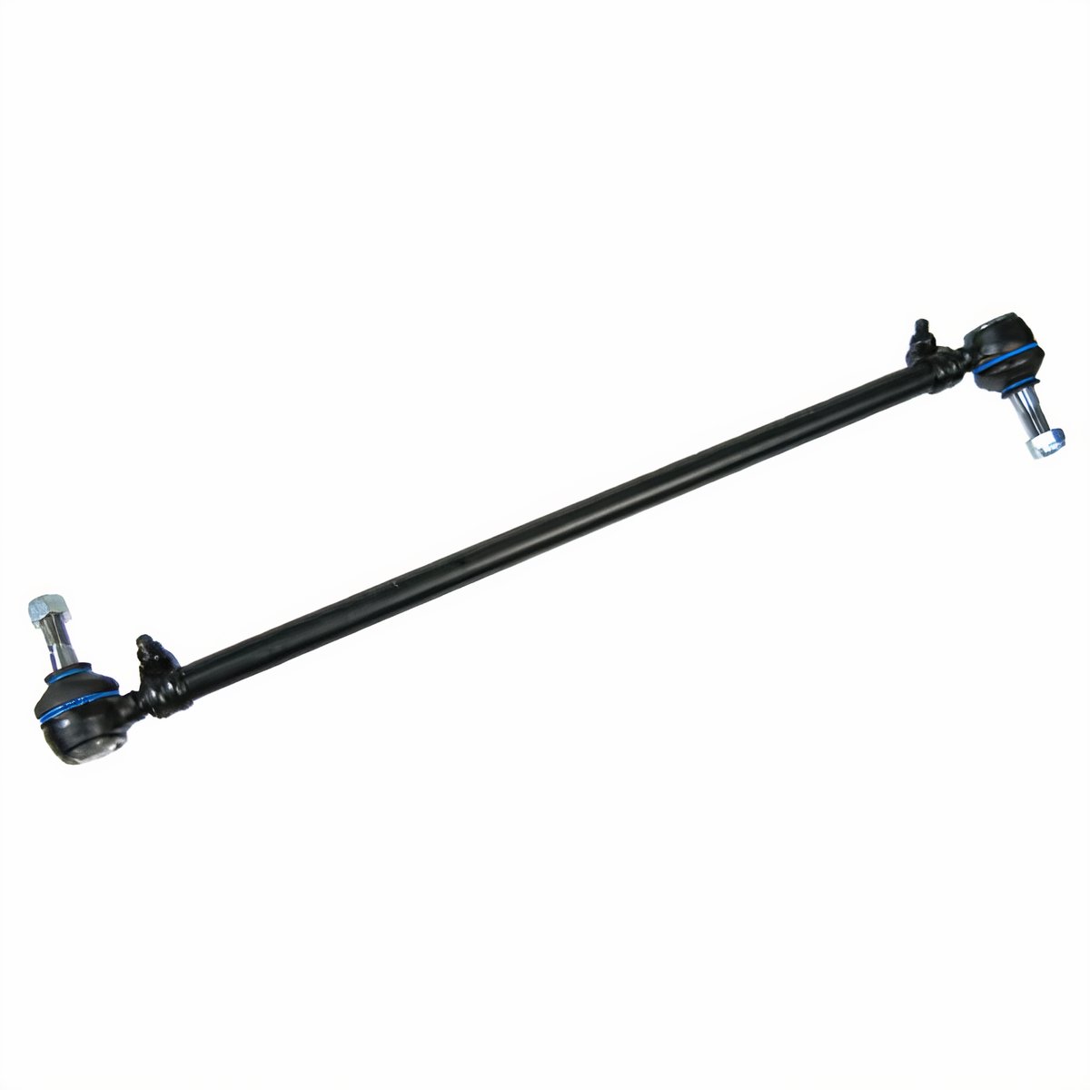
JBugs image of a tie rod
I ordered a pair of tie rods from Discount Import, and had T pick them up for me while he was there getting parts for Nemo (the A4). They charged me $35US each. The replacement was fairly easy. I started with getting the wheels as straight front-to-back as I could, centering the steering. Then, I replaced an entire arm, one at a time. The arm runs from the swing lever to the steering knuckle across the rear of the front beam. Each end of the tie rod has a 90* "end" on it that allows for controlled rotational movement. If the end can move at all any other way, it's bad. Since one of my rods was bent, I replaced the whole assembly, ends and all.

Rods Out
The ends are nutted down with castle nuts which are held in-place with cotter pins. The cotter pins may have rusted into place on yours, requiring more coaxing than mine did. Even as original parts, I was able to bend the pins back and push them out. Then the nut comes off. Last, the end needs to be separated from the knuckle or swing lever. This usually requires a pickle fork and a hammer, which will destroy the rubber boot on the tie rod end, so be sure to plan accordingly. I was able to free the tie rods by hammering away on the pickle fork. The passenger side released from the swing lever with just a couple whacks. In contrast, the driver-side steering knuckle took many many more. I have read of some needing to apply heat with a torch to get these to separate, so be prepared. Once removed, I cleaned up the holes with some WD-40 and a rag. Then, I scrubbed them with some sandpaper to make sure there weren't any sharp edges left around the holes from my removal efforts.

Rods In
Nicked from Interweb,
shows swing-lever end
and steering dampener
Oftentimes, the supplier will sell/send you two adjustable rods. This may be correct for some cars, but for the old bus, one of them is supposed to be fixed length. Discount Import only carries the adjustable rod, so the opportunity to do this wrong goes up. I followed this process for the not-bent side: measure the old rod from end to end on the top side (opposite where the threaded bolt comes out). I then adjusted the replacement arm to that same length, and then tweaked it until it dropped right into the holes. For the bent arm, this process wasn't effective. Measuring a bent arm wasn't going to get the exact length, so instead I matched it to the not-bent arm on the other side. Rather than touch the steering wheel or the tires, I adjusted the arm until it dropped into the holes. With the arms in-place, I could do a ShadeTree front alignment. Replacing the arms took less than an hour, so even at my "my free time is worth $50 an hour" rough math, I saved over $350 doing it myself versus having HM Motorsports do it.

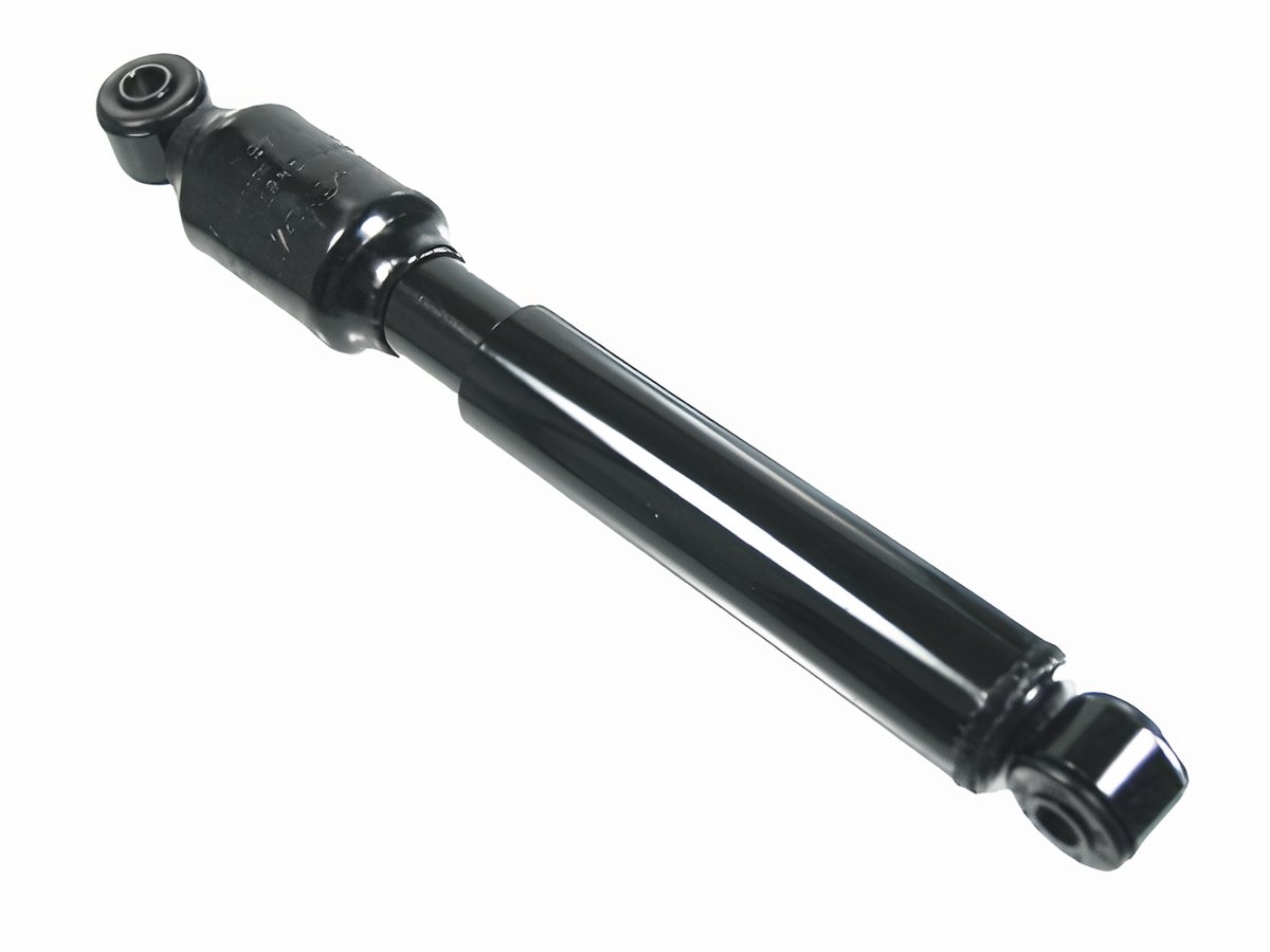
Steering Dampener
Jbugs again
Before I put in the new rods, I took the opportunity to replace the steering dampener. This is a small shock-absorber that helps cushion the driving experience at the wheel from sudden jarring affects of road hazards. Consider how much the steering wheel hops when you hit a pothole. For a car with a working front-end, it's not too bad. If your steering dampener is shot, the steering wheel gets a mind of it's own for a second. That's dangerous at any speed. In the bus, with the higher center of gravity, it's downright scary. I highly recommend replacing yours if you have no idea how old it is. I got mine when I got the tie rods for $30US. It's held on with 2 bolts (17mm, if I remember right), like a shock absorber, and it is actually pretty easy to get at when the tie rods are off.

ShadeTree Front Alignment
With the steering dampener and tie rods refreshed, I was ready to get the alignment roughed in for a test drive. All cars are a little different, so the measurement below may not work on yours, but it worked on the bus.  Measure the distance between the front-most part of your front tires (looking at the front left tire, at 9 o'clock). Now compare that to the distance between the rear-most part of your front tires. The measurement from the front should be between 0" and 1/4" smaller than the measurement from the rear. The varying length depends on your tire size; I'm running stock diameter, so this works. Ultimately, this effort should be sufficient to get you to the alignment shop. This is not an ideal permanent setting.

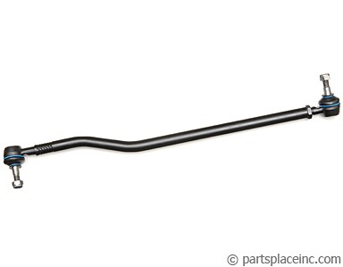
PartsPlace.com image
If you have just one adjustable tie-rod, the adjustment is more straightforward. Since I had two, I adjusted both sides one turn at a time until I hit the 1/4 inch number. Based on how the arms adjusted, I used to have no-toe or a slight toe-out. In my experience, the steering becomes less predictable with toe-out, so I'm good with a slight toe-in. I test drove the bus first slowly in the driveway, then into the dead-end street and finally around the block. The steering held much more firmly over bumps and when the street was level, and there were no bumps, it held a straight line with my hands off the wheel. There was still 3-4 inches of play at the wheel, though, when I did want to change direction.

Drag Linking
To resolve the remaining play at the wheel, I asked Boo to sit in the driver seat and turn the wheel left to right while I laid-hands on various parts of the steering system. I could see the steering coupler turn, and feel the arm move, but the drag link didn't move right away. It had a significant delay, and made a clunk noise when she changed direction from right to left (not left to right, which was weird). I rested my hands on the swing lever to see if it had any up/down movement. I couldn't feel any, so that lever and the pivot pin should be fine, unless my novice hands couldn't feel well. Other than the steering box, the swing lever was all that was left if replacing the drag link didn't fix the steering play. I resolved to replace the drag link, and bought one at Discount Import ($50US). If they had had a swing lever kit, I would have bought one since the 90 minute round trip can eat up a day if you need to do it more than once.

old drag link,
broken pickle fork
The drag link removes just like a tie-rod: pull the cotter pins, remove the castle nut, and apply force with a pickle fork to pop each end free. The drag link removes and installs from the front with the non-adjustable end pointing to the rear. I broke my pickle fork as you can see in the picture to the right. I guess the Harbor Freight fork isn't made very well.

Similar to the tie-rod, you want the replacement to be the exact same length as the old one. In the PartsPlace.com image above, you can see an adjustment lock-nut on the right end. I placed my old and new side by side to get the length correct. Take care as you pass that rear "end" through the hole in the support so you don't damage or tear the rubber boot. I left the plastic shipping cover (visible in the picture) on the end during pass-thru so it wouldn't get damaged. To get the end to fit into the swing lever, I put a socket extension onto the bolt and used that extra torque to position the bolt to easily fit onto the hole. The front end slid right in without any extra fiddling, so I knew I had the length right. If you aren't so fortunate, repeat the measure and fit steps otherwise your steering will not align properly. Last, I threaded and torqued on the nuts, inserted the cotter pins and closed up the belly pan.

Test Drive
This final test drive was quite different. The steering is genuinely responsive, with less than an inch of steering wheel movement before the bus starts changing direction. When combined with the steering dampener, it drives like a completely different vehicle. I know I should take it to have the alignment done, but honestly, I probably won't. It handles so well, holds center during acceleration and braking. Since the caster and camber were within spec before I started replacing parts, and the parts I replaced have no bearing on those settings, I may let it ride as it is.

So, Hapy is fully operational again... just in time for winter. I have plans to address rust this winter, after I complete the interior of the MGB. And, of course, there's the 280ZX that neither C nor I have given much attention to. Clearly, I have lots of content waiting to be generated.

That's it for today. Thanks, as always, for following along-

Tuesday, July 11, 2017

MGB - Steering Rack Install

I realized that I didn't post about the install of the steering rack, so today I'm going to have a quick post about that. For reference, I removed, cleaned and re-assembled the rack in this post.

Pre-Alignment
steering arm seated in clamp
Before you start putting the three-armed monster in (what's that? See MGB - Steering Rack), check that it's centered left-to-right by turning the steering arm. Next, check that the steering wheel is straight, the center spokes level with the bottom of the car. On the other side of the firewall, you should be able to spot the steering column butting out. There is a clamp on the end for the three-armed monster to fit in. The clamp has a bolt/nut combination which needs to be removed from the clamp before assembling the three-armed monster. That bolt needs to align with a cut-away on the three-armed monster steering arm. So, look at the two ends, and recognize that if the steering rack is centered within itself, but not centered once the cutout aligns, your steering wheel won't sit nicely level. Fixing this could be as easy as a minor adjustment during alignment, or more complex like removing and re-installing that clamp or doing something to the steering rack. In my case, I was putting the old rack back in, and the wheel was close to level before.

In She Goes
If you're doing this alone, like I was, getting the monster in can be a juggling act. The column arm fits around the right engine mount bracket. Get the unit in the right general location, and use a rubber tarp strap to hold it there. Believe me, holding the monster in the right general location while also trying to do the fine motor work of getting the arm into the clamp is simply impossible by yourself. Once successfully suspended, set the steering arm into the clamp. If the clamp is not amenable, it has a split down one side where you can coax it open with a wedge. Once you have it in the right alignment, slide under the front of the car and drive it into the clamp with a rubber mallet driving against the housing. It should slide in with only a few light strikes. Remember, that's a $250 part, so rap on it gingerly.

The rack is held to the frame with 4 bolts and 4 nuts with some washers. Get replacements. The bolts closest to the firewall drive into nuts which are part of the mount. They thread in pretty easily. Just do enough to get the threading started. The bolts closest to the front use a pair of nuts each. Yes, I said that right. The order of the fasteners from the top: bolt head - washer - steering rack - nut - frame bracket - washer - nut. The nut between the frame bracket and the steering rack is absolutely necessary to not bind the steering action. Yes, I tried it without the nut to see what would happen.

Tie-Rod Ends
I blasted The Roadster Factory for their return policy and continued sale of junk tie rod ends. Get the sealed OEM ones, and use a different vendor if you can. There are a few out there. Assuming your new ends are the same size as the ones you removed, you should be able to thread the new ends to the marks you made earlier. I determined during my "Rough Alignment" that my new ends had more housing to them, knocking my measurements off. Had I to do it again, I would measure from the edge of the steering rack housing to the outer edge of the tie rod end instead. Regardless, thread on the tie-rod ends and set the wheel-end into the arm on the swivel, and finger the washer and nut on. Don't tighten yet. There's rough alignment to do first.

Rough Alignment
There are a few ways to get the alignment roughed-in. By roughed-in I mean close enough to drive it to a shop to have someone with a machine do it. It's possible that you could do it as well with one of the methods, but I encourage having it verified. The easiest method is simply looking down the line of your car and matching the front wheels front/back along the body line. I did this first, once I discovered how toed-out my front wheels were.

Changing your alignment is pretty easy: pull the tie-rod end out of the steering knuckle and rotate it on the tie-rod clock- or counter-clock-wise to move the end in or out relative to it's prior position. There is an alignment lock-nut just to the inside of the tie-rod end that will need to be loosened before you play with the adjustment.

After the body-line rough-in, I would encourage the measuring tape method to rough-in your alignment. Measure the distance between the inner edges of your tires both behind and in front of the swivels. If they aren't the same, you may have adjusting to do. Ideally, the front is slightly narrower than the rear for better handling and stability. This measurement should happen with the wheels on the ground after wiggling the steering a little bit and then centering as best as you can. It will take a few tries to get it right. Once you think you have it, tighten the lock-nut and test it in your driveway. I still need to complete this on my MG, but the steering is close enough now for me to move the car around my driveway / garage.

Regardless of which rough-in you try (and there are probably others), don't assume it's right. The idea is simply getting it close enough to take to a shop. If you aren't confident with your rough-in, have it towed. If your car is anything like my bus, it's getting used to riding on a flatbed.

That's it for today's brief posting on getting the steering rack back in. More to come soon, and, as always, thanks for following along,

Tuesday, May 16, 2017

MGB - steering rack

The last collection of posts have been about this project MGB I picked up last Summer/Fall. Today's post covers the efforts of removing, cleaning, and repairing the steering.

Context
The steering on these little British cars is only a hair more complicated than the old VW bus. The bus uses a system called "worm and peg", which is definitely not used in modern cars. Without opening up the steering box, consider that there is magic inside this box with two arms coming out it. The arm coming out the top connects to your steering wheel and the arm coming out the back connects to control arms that terminate at each of the front wheels. Within the magic box live the worm and peg. The "peg"  rides on the "worm" that is a threaded bar that looks like an auger. As the steering moves from lock to lock, the worm moves the peg from side to side, causing the front wheels to turn. Simple design.

3-armed monster
The MGB has a rack and pinion style. Rack and pinion has a gear (pinion) at the end of the steering column that rides on a "rack". The rack is simply a toothed bar to which the control arms are attached. In the case of the MG, the control arms and the rack are all one piece. Power steering includes more bits to boost the power of the pinion to move the rack. The MGB doesn't have the power assist, but its a tiny car with little weight, so there isn't much need. One other interesting bit about the MGB steering is that over half of the steering column is part of the steering rack so it has 3 long legs/arms to manage on extract and install.

Getting It Out
just removed. note torn d-side boot
Removing the steering rack from the MGB is actually pretty easy. For me, someone who takes forever to do even the most simple of jobs, that's a big statement. At the ends of the control arms are tapered "ends" that fit into the steering knuckles (sometimes called "swivels"). Since I had already decided to replace the rod ends, I separated the ends from the knuckles with a couple of smacks with a hammer. There are gear remover tools that are more graceful, but if you're replacing the ends and the nuts (always replace the nuts) anyway, a hammer works great.

p-side arm measured
With the ends separated from the knuckles, move up to the steering column part up near the firewall. Mark the way the two ends come together so your steering wheel will align properly on your first re-install effort. I shot the joint with a pop of spraypaint, but that was only because I couldn't find something like a paint pen. You can just see the marks in the picture on the right, here. Once marked, loosen the connection so it doesn't hang up on you later.

In order to easily get to the rack bolts, you may need to remove the little section of cowling between the radiator and the front beam. It is made of glueboard and held on with a couple of nuts. There are metal replacements for the cowling available, if your original is trashed. Once you have access to the rack, it is held on with 4 long-ish bolts. With those bolts removed, the rack can be removed by pulling it forward and down. If it isn't budging, check that the steering column is loosened enough.

Cleaning
p-side arm measurement
My rack was leaking, and was identified as a possible replace item by the shop. K2 and I saw that the bellows on one side were definitely torn, so I ordered a replacement set as well as replacement arm ends. We (step-son K2 helped a bunch here) started with simply cleaning everything up first. K2 used "Simple Green" and a lot of elbow grease to get the arms and main cylinder clean.  You can't put new bellows on while the arm ends are still attached, so when it was clean, I marked the control arm end positions with a shot of spraypaint (use a paint pen if you have one). Once marked, I removed the arm ends, and then the bellows. At this point, K2 doubled down on cleaning. He turned the steering from post to post, cleaning up any gunk that he found in the teeth. We removed the cover plate and looked for broken teeth on the pinion as well.

Repairing
Junk. Don't Buy These
The pinion had no broken teeth and the arms were in great shape. We decided not to replace the steering rack, and just re-seal the cover, refill with oil and replace the bellows. I used a very light application of form-a-gasket to help seal the cover. If you use too much, it gets into the gears, and that detail cleaning needs to be redone (guess how I know that). Before the cover plate is sealed on, the bellows need to be put on. Put a little bit of gear oil on the inside edge of the small end before you start. This allows the small end to slide over the end of the arm without tearing. Attach the wide end to the main cylinder and a-fix with the metal band. Before attaching the small ends, check where they should go so that they don't stretch nor bind when the rack is turned lock to lock. If you have marked the old location, its easy. I didn't but I found that once I started zeroing in on a spot, it actually was the same original position (there were tiny scratches on the arms). Tighten the small ends down with the smaller metal bands. Now, fill the system with gear oil: 90 weight (like the VW bus transaxle). "Fill" is about 8oz.

Ends
OEM. Buy These
Once everything above is done, all that's left are the ends. There are two kinds available out there, and I bought both to see the difference. These cars came with sealed ends that allowed no maintenance. So, if you thought your end needed grease, you can't grease it; you need to buy replacements. These replacements are made in England, though, so you're getting a good OEM part when you go this route. There are also replacements available which have a grease fitting. These are Chinese junk. The concept is great, the execution is appalling. The pair that arrived were rusty and the main rubber seal was falling off. Not only would it not hold grease, the rubber "seal" wouldn't stay on at all. I was only able to find them at the Roadster Factory, but don't shop there. When I alerted them to this poorly built part, and returned it according to their rules, I received no communication nor any money back. Vendor: if you sell garbage and then don't honor your own policy, you're a sham to me and will be called out accordingly: do not shop from The Roadster Factory unless you're willing to accept crap parts with no means of return.

Ends On
The OEM part, as expected, looked perfect and fit as you would expect. I threaded it on to the marks and tightened it down.

I am finishing up some other tasks before re-installing the rack, so I will post again when I have that completed. Thanks, as always, for following along.