Tuesday, April 2, 2019

Speaker Box Install Finish

I left off the sound system with some test fires and some lingering to-do's. Today's post covers the completion of those steps.

Shorter RCA Cables
The first and easiest to-do was replacing the RCA cables from the head unit to the amp. I originally used cables that were thick and over a meter long (about 4 feet total length). With the head and amp so close together, this left me with lots of extra cable looped all around. I found a vendor on eBarf and had 18" cables delivered. These were perfect, leaving me enough extra cable to maneuver things, but without a bunch of extra to deal with.

Ring Terminal Ground
original light location
note the fuel tank vent / hinge springs
When I first put things together, I didn't have a ring terminal for the ground wire. We were in the middle of a late-winter snowstorm, so getting to the corner hardware store was not in the cards. I didn't want to stop my efforts so I slapped together a ground using a washer and some electrical tape. It did the job, and once he weather improved, trading this hack-job for a real ring terminal was easier than trading out the RCA cables.

With those two things done, the front end of the system was complete. I had a couple of nagging issues in the trunk to deal with, though.

Trunk Light
Back in the boot, I had the speakerbox fit onto the little (less than 4 inches deep) shelf, and against the lots-of-holes-in-it rear fire wall. The speaker was propped up by an old sub woofer that I wasn't going to use. It served the purpose of showing how the speaker would sit, but that wasn't a viable long-term solution. What it revealed was that the trunk light, which sits in the center of the trunk opening furthest forward, would be mostly blocked by the box. It lit up the top of the box beautifully, but the trunk was now mostly dark. So, I moved it.

new light just above latch
The trunk light housing is held to the "beam" that runs over the top of the little shelf by 2 Phillips head screws (picture at right). With these removed, and the purple-circuit fuse pulled, the housing can be lowered. I set the bulb aside and pulled out the feeder-wires from the housing. Those wires were then back-fed through the openings in the body until they were hanging loose by the right-side hinge where the switch is. I cut the 2 wires around the midway point, and then started experimenting with new locations. I decided to mount it to the underside of the trunk lid, just aft of the mount-points for the MG medallion which sits on the trunk top side. There is a cross-member here which provided a place to put the screws through without creating through-holes.

I sent the wires from the housing through the trunk-lid cavity, and found I needed about a foot of wire to re-connect it to the switch. A few minutes of scrounging, cutting, wiring and taping later and the circuit was reconnected. I stuffed the wires into the trunk lid cavity and cable-tied the wire bundle closest to the hinge to the hinge so they wouldn't get hung up on future parcels in the trunk. I replaced the bulb, put the plastic cover on and replaced the purple circuit fuse. Tada! Light fills the trunk better than it did before and the light itself is not in your eyes anymore. I will need to take care with objects shifting in the trunk, though, since the housing is now down near the latch.

Strapping It Down
With the light solved, I needed to create a means of attaching the speakerbox to the car. I want the box to be easily removable, in case we want good sounds at picnics, or if I ever want to use it in Hapy. I also wanted to minimize ant further impact into the storage space in the trunk. So, adding to the little shelf or adding drop-feet to the box were not options. Instead, I thought through options to hold the rear top edge up and forward rather than extra support from below.

I got a spool of 1" nylon strapping. These are used on backpack shoulder straps or gym bags and are super strong. I cut 2 1-foot lengths, and looped one end of each around the tank vent / hinge-springs that run the width of the trunk opening at the front edge. These looped from above, with about 1" of overhang below. I super-glued the edge of the 1" overhang to the longer side, and tested by pulling on them. To these straps, I threaded on the female side of a nylon strap buckle. Now, I had something to attach to in the car, the speakerbox needed something too.

I bought some footman loops for the box-end. I put one footman loop on each end of the rear side of the box, 1.25 inches from the top and 2 inches from the edge. I repeated the nylon strapping process I did in the trunk with the overhang hidden against the box. I threaded the male end of the strap buckle onto these. After a little wrestling and fiddling, the box sets and is free-standing-ish. To install the box, I put the bottom front edge on the little shelf and then lift the box upright while holding the car-side straps to the sides. Once the box is upright, I click the buckles together.

There are always little things that could be changed or improved, but I think, for now, the work is pretty much done. I changed the way the wires connect through to the speaker for greater ease of install, for example, by adding in RCA connectors between the speaker and the speaker wires. That hardly warranted a post, but it was completed once the parts arrived.

Top Down Test Drive
We had a taste of spring with sunny skies and temps in the upper 60F's (about 20C) so Boo and I took Oliver out for a quick spin. I had installed the passenger seat (not post-worthy, it was a basic install with no discoveries nor bungles), so we were ready. Boo hadn't been on a ride except for a short drive down the street and back last summer so we were way overdue. I dropped the top, and pulled into the drive where Boo hopped in. We drove around the local neighborhood and easily chatted over the slight wind noise. We tested the sound too, and while it doesn't sound as good when it is sitting still in the garage, it sounds way better than I expected. The bass is full, the highs are present and the mid's cut through. Yes, there is wind shear, and some of the signal is lost, but most of that loss is filled back in when the volume is turned up. Boo and I agreed that the new seats are super comfortable, and the car would be perfect for a road trip. We just need a reason and a destination.

That's it for today. Thanks, as always, for following along--

Tuesday, March 26, 2019

MGB Charging System fun

Brief post today about an electrical breakdown deja vu but this time it's Oliver ('78 MGB), not Hapy ('72 VW).

Charging System Basics
Most cars have a relatively simple "primary" electrical system. There's the battery which holds lots of stored power for starting the engine and regulating the secondary power usage. That part is obvious. Wired into that battery are the starter and the alternator (or generator in older cars). These are motors for opposite functions. One, the starter, eats the most power while the other generates power. Connecting these together are wires and the ignition switch. Seriously, that's pretty much it for the charging system. There could be a voltage regulator (VR) between the alternator and the battery, but oftentimes these are integrated into the alternator so you don't need to worry about them independently. The VR is separate on the original '72 bus, mounted on the right side of the firewall in the engine compartment. There are lots of other things connected into the electrical system, of course, but for today I'm focusing on getting the the battery to charge.

And We're Talking about this Why?
from 123ignitionusa
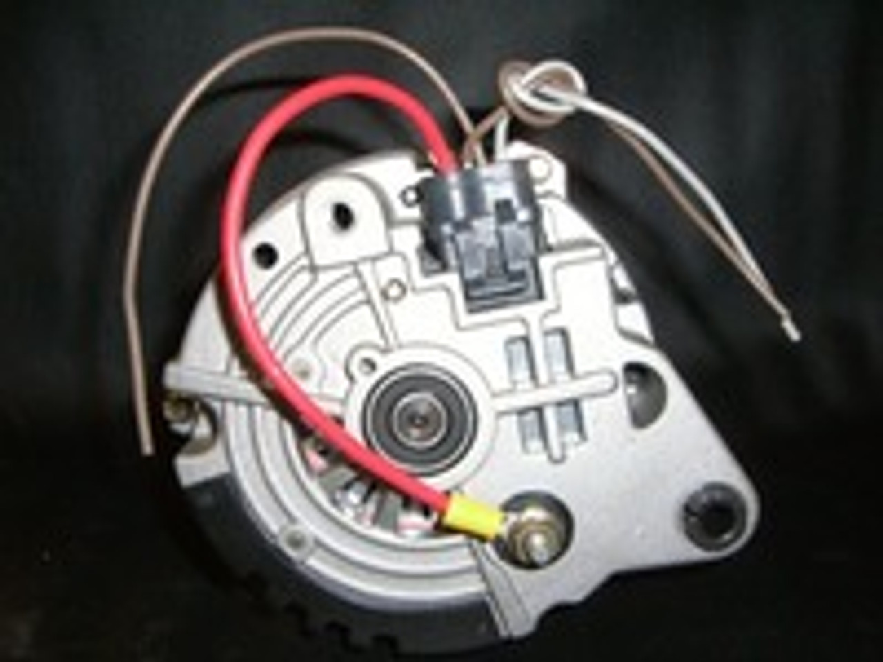
Back when I had the MGB looked at by the local British car experts, they indicated that the charging system was sickly. I swapped out the battery. I still found myself charging the battery up an awful lot so I bought and installed an alternator upgrade (now at 105 amps). Neat. You can find them here. But the little car still died on the side of the road a couple of weeks ago, with an electrical failure. After our adventure coming home from Furthur in 2013 (See Tale of Two Trips) I knew what an electrical failure looked like. Lights dim, wipers slow down, fans slow down and then the engine starts to miss. Soon, it won't keep running and you're gliding to a stop on the shoulder. If there is one. The last tip: the hazard lights don't work. Which is especially great when you break down in an exit lane where there is no shoulder / break down lane. Like here: (45°28'37.3"N 122°47'25.8"W).

Fortunately, it was mid-afternoon on a Friday, so the traffic wasn't too bad. I got AAA on the phone and stood behind the little orange car in the sprinkling rain waving cars around me. While waiting for the truck, an ambulance pulled up behind me. One of the guys helped me push the car some of the way up the ramp. At the intersection, a couple of guys hopped out of a car and helped push the rest of the way up the ramp and around the corner to where I could turn onto Allen Blvd and coast downhill. I came to a stop around the corner on King and Lee where Oliver was loaded onto a flatbed.

Root Cause
LM 11009 (BA7s)
bayonet bulb
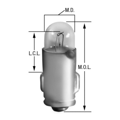
In my list of items included in the charging system, I failed to mention one last thing: the charging system failure light (labelled "Ignition"). This seemingly innocuous light bulb does more than just tell you when your charging system is fried. Of course, it does that and it is able to do that because of this other purpose. It provides a light 12v current to the alternator through a means other than the thick battery-direct cable. When that 12v meets another 12v coming from the alternator, no light. When the 12v meets ground, the light illuminates. Cool. This small 12v signal also initializes the magnetic field in the alternator so it can generate electricity. Without this little signal, there is no field, so no power generation, eventual system failure while you're trying to exit OR217. Neat. So, at some point after learning that my charging system was sickly, that little bulb died. Did I need a new battery? Maybe, the old one wasn't too old, but it was a discount brand. Did I need a new alternator? Probably, it was original and had the rust on it to prove it. Besides, 105 amps is far better than the 43 amps you get from the original or direct replacements.

top: blown bulb
bottom: new bulb
So, how do we prove this? Well, first, when you turn the ignition switch to run, you should see that little light. No light? Check the bulb. Assuming you missed that, or just want more proof, start your engine anyway and check the voltage at the battery while running the engine above 2000 rpm. If you're not seeing around 14v, you're not charging. Replacing the bulb is inexpensive ($2.50US per bulb at NAPA), though hard to get to. I was able to access it from under the left side of the dash by running my left hand up along the steering shaft, behind the tachometer. The bulb and harness are pressed into the plastic holder, and held in simply by friction. A slight tug on the harness will free it. The wires are kind of short, so getting the bulb down low enough under the dash so you can see and replace may be the hardest part. Well, that and getting the bulb and harness pressed back into place. Since I was up in there, I checked all of the bulbs, one at a time, to make sure I didn't have to get back up under there again any time soon. Fortunately, there was only the one.

Even if the "Ignition" bulb weren't critical to getting a charge, it is wise to run with all of your warning lights working. Gauges are great, but when you're enjoying the scenery or enduring bumper-to-bumper rubber-banding traffic, you may not note your gauges as often. A bright red light on your dash attracts the eye. And, in my case, I don't have a battery / charging gauge to tell me how well my electrical system is. I like the stock look, so I doubt I'll change that, but if I wasn't thinking about it before, I kind of am now.

Anyway, that's it for today. Thanks, as always, for following along.

Tuesday, March 19, 2019

Car that Goes Boom - Part 2

Continuing the fun from the last post about the amplifier install into Oliver. When we left off, we had selected an amplifier and an install location. I had concocted and fabricated brackets to support it, installed the amplifier and did some tests, both by sitting near it as well as a road run to verify the brackets held. Today, I will go through the wiring aspect and fire this thing up.

Wiring Rear
In the last post, I mentioned there are 2 methods for wiring signal to the amp. I used the pre-amp / RCA cables method. To achieve this, I first needed to find and label 6 RCA cables. I found a few old RCA cables from my A/V stash, but they were over a meter (4 feet) long. On each wire, I marked a (F)ront, (R)ear or (S)ub prefix and (Left) or (R)ight. I did this on both ends. Why? So no matter which end I was doing maintenance on (or replacing a component) I knew what the wiring was without having to jiggle wires or unhook the other thing to figure it out. On the amplifier end, I plugged the cables into flat 6-pin pigtails, keeping the F/R/S wires together. Next, I pulled the stereo out of the center console, and passed the RCA cables through. There are a few wires that need to be removed from the big plug in the back of the stereo, and the rest remain. Simply: all of the speaker wires need to be removed from the plug. Consider, the "signal-on" wire needs to be made available to the amplifier. I had not used it at this point, so I needed to add an extension so it would reach. With the RCA cables plugged into their correct holes in the stereo, the power, switched power, ground and "signal-on" wires connected, the stereo can get put back away. Last, I plugged the 6-pin plugs into their respective slots on the front of the amplifier, noting that "(F)ront" goes to channel 1/2, "(R)ear" goes to channel 3/4 and (S)ub goes to channel 5.

There is a 4-pin for the remote bass and "signal on" as well. The remote bass is a knob that I will install later. For now, it is tucked behind the center console near the driver side foot well, but it is wired. The signal on wire I had located was connected to this pigtail and heat-shrinked. To keep things clean, I zip tied the bundle of cables and wire together, and tucked them into protective wire wrap (like this) I picked up at Harbor Freight. The black wrap made the cables disappear. I routed the whole thing up and over the top of the amplifier before routing it behind the center console. This should keep the bundle out of the passenger's feet while still keeping the controls available for fingers.

Wiring to Speaker Box
clamped screwdriver as wire spool
Up until now, the wiring going to the rear of the car had run through the cockpit. I ran the 2 wires along the transmission tunnel on the passenger side. Now that I was adding another pair of wires, though, the cable had become too thick, and was making a lump under the carpet. So, I decided to route the speakers under the car. Again, leveraging protective speaker wrap (smaller diameter this time), I routed the wires for the 2 rear speakers plus the sub woofer to the front of the car through a wiring feed hole (mostly hidden by the sub box). I think it used to control the fuel pump because it has spade connectors in it. From there, the cable ran along the underside of the car with the other bundle of wires that run front-to-back all the way from the fuel pump to the starter.

Because of the location of the wiring hole in the trunk, I did not leave much slack in the wires back there. Instead, I considered ways I could get the wire bundle to stay up against the box. I decided to leave the cable wrapped almost all the way to the sub-woofer plug, and figure out how to tidy it more later. With the other ends of the wires for the speaker box hanging under the glove box, I was entering the final phase.

Wiring Front
$3 wire wrap protects
Out the back of the amplifier are 12 threaded-bolt wire mounts: +/- for both front (4), +/- for both rear (4), a pair for the sub (2), and one each for ground and power. Since I had done everything else so cleanly, I didn't like the idea of running a bundle of wires at the amplifier. For maintenance and ease of amplifier removal, I wanted something easier. Also, the only slam on this amp in the reviews was about these connections, so I wanted it to be set up once and then forgotten about. So, I got some multi-wire connectors from BritishWiring.com. With these connectors, it would almost look like it was part of the original MGB. Unfortunately, they don't sell any even numbered pins, so I used a 9-pin for the front/rear speakers and a 3-pin for the sub. I wired a few inches of wire from the amplifier to the male plugs (see the second picture from the top) and then wired the speakers and ground/power into the female plugs. That sentence was quick to write, but it took me a several hours of effort.

Wiring Power and Ground
Test fit - RCA cables too long
All I had left was the ground and power. I had intended to use the extra pin on the odd-numbered plugs. When I set out to do the wiring into the plug (see top picture) I quickly discovered that the 10 gauge power/ground wire needed for the amp were very different animals from the 14 gauge speaker wire I had in the rest of the plug. Quite simply: the 10 gauge was too thick to pin. So, I bought a 3rd 2-pin plug designed for a GM alternator from the local NAPA. It had male and female plugs on it, so I could cut it into two pieces and continue the plan. Similar to the other plugs, I put the male end on the amplifier side and wired the female end into the car. With a ring terminal on the black wire (ground), I leveraged the rear bolt from the amp mount. This was a solid ground, based on my connectivity and voltage tests. For the power, I ran a blue wire from the alternator, through a 10A bladed fuse and through the rubber-lined wiring hole in the firewall behind the glove box. This dropped the power supply nicely near the amp.

Once both were connected through to the plug, I was ready to plug everything in for a test. I think, ideally, it would have been better to wire the power into the battery, but the battery is behind the seats, so the wire run would have been longer, creating a greater likelihood of a short. I ran a couple connectivity tests to make sure everything was set to go, and then re-connected the ground on the battery.

Test Fire
I had already identified a couple of things that needed to be changed, but with everything hooked up I wanted to see if it worked before I started changing things. So.. in short, the speaker wires were moved from the head to the amp, the amp was wired with power and grounded, and the power-up signal from the head was routed into the amp remote switch. Everything should be set to go. With the battery still connected to a tender, I slapped the face back onto the head unit and turned it on. All the lights came on, but I couldn't hear anything. I turned the stereo way up and could barely hear sound, so I concluded the gains on the amp were too low. Second attempt: turn the stereo back down to single digits and turn up the gains. Now we have sound.

With Rush's "Spirit of the Radio" cranking, I set the various levels so Getty Lee's bass snapped and growled, Neil Peart's drums punched and Alex Lifeson's guitar sang. It sounds so good inside the cabin with the top up. Once I get out, the sound really doesn't travel outside of the car as much as I would have expected. Of course, once the top goes down, things will change. This leaves one last test: driving at speed with the top down. That will have to wait until Summer. In the meantime, I tried the classical station for a different sound signal and it sounded really good... but not as good as Rush did. There's just something about Rush. Maybe it's the punchy bass. Whatever it is, the next test will be an early Dead show, like, maybe, the Music Box from Feb 1968, and then a wall-of-sound show.

Thanks for following along. I still have to install the passenger seat into Oliver, and then I may start working on the interior door panels. Or, maybe, I'll just finish the trunk. I don't know. I'll see how I feel when I get to the garage.