Showing posts with label mount. Show all posts

Tuesday, January 27, 2026

Hapy Re-Assembly Continues

First, thanks for following along. I know blogs have fallen far out of favor, with videos and such being the preferred means for getting information. I can't watch videos at work, but I can read, so for me, this is still viable. There's an old saying about not having a face for video, or a voice for radio, you can still print. That's me. Besides, I barely have time to do my thing and write about it, much less shoot and produce video. I don't know how those content producers get any sleep, especially the ones who aren't making any money at it, which, lets be honest, that's most of them. More power to them, and I greatly appreciate their efforts. When I finally wind down at night, I love me some car-fixin videos.
 
So, where were we? Oh yeah, Hapy was almost assembled. Well, his engine and transaxle were mated and they were mounted to the bus. That's the fun, exciting, sexy part. What's left is everything else. I stayed under the bus and finished everything there first before getting after the from-above stuff. I didn't take any pictures, mostly because with all the extra layers simply moving around under the bus is a challenge.
 
Transaxle Finish
I started at the front and worked by way backwards. This started with the nose-mount. At some point when the transaxle was removed, one of the mounting bolts broke off inside the threaded body mount. I know I need to resolve this, and practically every time I get under the bus, I shoot that broken-off bolt with some penetrating oil. I believe the front mount carries very little actual weight, but it does make sure the transaxle remains aligned. I gotta get that bolt out and replaced, but not today. With the one bolt in, I connected the grounding strap. I slid to the left side and connected the Bowden tube and clutch cable. I make a point of leaving bolts partly threaded into where they go so (a) I don't lose them and (b) so I know where they go when I return to a project 6 months later. This made installing the Bowden tube just the usual challenge and not accentuated with a bolt search first. To make the threading of the butterfly nut on the end of the cable easier, I prop up the clutch pedal and then put vice-grips where the cable meets the threaded end. Lots of tightening later, I then test the play of the pedal and slide back under a few times to make sure the pedal has an inch or so of travel before the pedal meets resistance.
 
The last thing on the transaxle is the reverse light plug. In my efforts to install, I smashed the reverse light plug quite a bit. Perhaps this happened when the transaxle fell of the jack this past summer. Hard to know. Anyway, with needle-nose pliers I straightened them out. The leads, have been in the same position for so many years that they were already pre-oriented for the right spots to plug in. 
 
Rear (Anti-)Sway Bar 
Sliding further rearward, I got after the rear sway bar. I will again mention how helpful this bar has been for handling, especially in a strong cross-wind. I will also stress how important it is to have it out of the way for a transaxle R&R. I raised the center of the bar with the TravisJack so I could use both hands on the various mounts. I made sure to put a small smear of clear, hi-temp grease (not black axle grease) on the hard bushings, finger-threaded everything and then nutted every thing down. The grease extends the life of the hard bushings, by reducing the direct-wear of hard bar twisting against them. I had not greased these previously, but we really have not run more than a few hundred miles since I put this bar on.
 
Starter
Now we're getting near the end of the below-the-bus stuff, with the starter going in. With the newer starter adapter, with the studs to hang the starter on, the install is much easier. It really is as easy as popping on there and nutting down with a 17mm socket. The top nut can be a challenge to reach, but the rest of it is easy. Pop on the 12V send from the battery and the 12V send-to-front onto the main post, nut down with a 14mm. Last, pop on the starter trigger. Done. Next!
from warmer summer days

Before sliding out, I hooked up the ground from the right side of the engine to the frame.
 
Fueling
For the most part, I left the fuel system in-tact. Right now, I start to feel the advantages of not pulling the motor all the way out of the engine bay. All I did to enable this job was remove the big Caterpillar fuel filter from the frame, and drape it on the engine. So, a couple of bolts later, the fuel system is back together, hopefully holding prime.
 
Cooling
Similar to the fueling system, I minimally disconnected the cooling system. So, I thought it would be just as easy. I lifted the overflow bottle and noticed the bottle was low, and could hear splashing noise coming from the driver side. I lowered the bottle and the steady stream stopped, so clearly there was a breach up higher in the system, and not a breech in the radiator cooling lines or something that would have potentially cost me all of the coolant. Sure enough, the coolant temperature sensor that plugs into the coolant outlet flange was loose and the c-clip was no where to be seen. It is highly likely that the clip was lost last Summer. At this point, I ordered a replacement, and moved on, but not without laughing at how, again, the coolant outlet flange bit me again. 
 
Charged Air
All I removed from the charged air system were the 2 silicone elbows that connect the inter-cooler to the system. Then, the inter-cooler can be moved out of the way for the work. The silicone elbows are held in-place with large clamps that require a special tool (or lots of patience with channel-lock pliers). I used both. Once complete, I noticed that the little blower fan I have on the inter-cooler was barely clinging to the inter-cooler so I fixed that with some new zip-ties. I intend to one day replace the air-to-air inter-cooler with an air-to-water system, reducing overall inbound air temperatures and freeing up some engine compartment space.
 
This was as far as I could really go without that little clip. So, this is where I stopped while waiting for them to arrive from ECS Tuning. While waiting for the coolant temperature sensor c-clip to arrive, I put the battery on the charger. Next time, we'll get after that little clip and whatever other adventures we uncover.
 
Thanks, as always, for following along- 
 

Tuesday, January 13, 2026

Hapy Re-Assembly

I have been waiting to do this post until after Hapy was completely back in one piece, but after many hours and days out there, he is still not quite together. Still, seems like as good a time as any to update, and, like seems to happen so often, this got long, so this is going to get split out. Perhaps he will be in one piece by the time I get the next post done. Anyway, I left off last time after having moved Hapy from the sloped and badly cracked driveway into the shop. That was in early October. With extreme work expectations, I had very little free time, so there he sat until winter break (mid-to-late December).
 
Time to Lean, Time to Clean
engine in, oriented
First, I moved the ATV jack with my wooden cradle under the engine and supported the engine. I started by removing the ratchet-straps I had used to hold the front of the engine to the frame and the axles from dragging on the ground. Then, I removed the rear mount, support tower and cross-bar. Last, I removed the rear tow-hitch / rear bumper assembly.
 
I was on a cleaning adventure, so I cleaned the engine bay and the parts I had just removed with de-greaser. Then, I painted those parts and the underside of the bus's rear end and lower engine bay with Eastwood's rust converter. I felt this set the stage for a less filthy job. Since I failed to clean the engine, however, I was only half right. But, the parts which were painted look really good now and I hope the rust growth is at least slowed, if not stopped, by the application of the rust converter. As they say "rust never sleeps" so it will remain on the inspect-every-time list regardless.
 
Transaxle Together
output flange going on
We start our assembly adventure by just returning the transaxle back to its state before I removed it. Recall that during my efforts to get the transaxle and engine to mate on the cracky driveway, the transaxle awkwardly fell off a small jack and onto the concrete, causing the left (driver in US) side output flange to pop off. This was what put the re-assembly effort into dead stop last Summer. After getting some advice, a new plastic cover and a few packets of grease from a shop around the way, I again did nothing about it for weeks. Work has been all-consuming this year, did I mention that? Anyway, continuing my cleaning frenzy, I cleaned everything (except the engine, it seems): the transaxle, the various parts, the area I was going to work in, my tools... you get the point. The little c-clip that was responsible for holding the flange to the transaxle was a little bent from it's rapid extraction by the driveway. The shop owner suggested that the original clip was higher quality than the EMPI stuff on the market now and encouraged me to flatten/fix that clip. So I did, with a vice and a hammer. With the mating points all clean, and the old little plastic cover gone, re-attaching the output flange, setting the c-clip and then setting the new plastic cover actually took as long to do as it just took to type. I was stunned it was that easy and felt rather stupid for avoiding this for, like, 6 months.
 
While I was there, I also took the shop owners other advice about removing the throw-out bearing, greasing the slide and re-installing the throw-out bearing. While the parts were apart, I hit the teeth on the output shaft with a wire brush, getting all the gunk out of the teeth. With the transaxle now back in one piece, I set it on a big sheet of cardboard and slid it under the bus, from the rear around the left side of the engine and over the rear sway-bar lying on the ground. 
 
I will make an aside about the rear sway-bar here. While it is great for handling, it is awful for getting the engine/transaxle in and out. It really is great for handing, though, especially in windy conditions. Simply disconnecting the frame mounts and letting it hang on the ground, leaving the shock mount ends connected, makes for a tall, virtually uncross-able, speed-bump for your floor jack. In the future, when I (and I suggest any reader who has the rear sway-bar) remove my transaxle again, I will completely remove the rear sway-bar from under the bus, leaving the space completely clear.
 
Tranny Meet Diesel
strapped to rotate
With the transaxle on the ground under the bus, I set to mating it to the engine. Right here is when I wish I'd remembered a few things:
1- while you can still interact with your transaxle, put the little cage on the shifter rod that comes out the front. I didn't and while it still isn't done yet I have already spent an hour trying to get the grub screw to thread in after the transaxle is already installed. Word to the wise: do this beforehand.
2- that shifter rod goes OVER the rear main frame tube. I don't know what it's real name is, but you need to put that rod over the tube before you try to put the transaxle into place. I forgot, mated the engine:transaxle and then had to do it again because I could not get the engine far enough back to get the shift rod over the tube. Total facepalm. Lost hours facepalm.
 
I am going to draft on this moment and drop a placeholder for consideration: Cutting in a removable rear valence like the earlier bus's had. I know the engineers made the fixed, permanent valence for structural integrity. Any other 1972 and later bus might still require it. For that matter, this bus may still require it. My bus, my risk ; I encourage others to not follow this advice without giving it some serious thought and even then, ask friends. My bus has 2 additional side-to-side heavy bars bolted into the side frames: one for the rear engine mount and one for the rear tow hitch. Both of these are heavy steel bars bolted in separately from each other. I submit that if I cut the rear to have a removable valence, I would suffer no structural loss. So, I think the next time I need to remove the engine, I will give this serious thought. How I do it so it doesn't look trash will be the fun part.
 
Anyway, once I got the shift rod over the tube, I set the transaxle on the "race" jack I got from our dearly departed brother-in-law, Travis (and named it accordingly). With the transaxle easily balancing on the Travis I was able to get the output shaft of the transaxle to align with the clutch. It is noteworthy that I did not use the "small" jack the transaxle fell off of this time; the big pad on the Travis is way more stable. I got the 2 to mate and threaded in 4 bolts to snug them together: 2 on the very bottom, one just above the clutch throw-out arm and one which threads through the starter mount.
 
Central Mounting
With the engine and transaxle as one large and heavy assembly, I needed to get it aligned with the 2 central mount holes: the 2 which pass through the ears on the top rear of the transaxle. I believe this mount handles the lion's share of the weight. The left side aligned fairly easily (20 minutes of wrestling) but it took a couple of hours of fighting the right side. I could not remember having such a hard time reaching and seeing. With a shrug, I went to put things away and noticed that I could not lower the overhead engine lid I'd cut in all those years ago. It was bopping on the intake. I realized that the engine and transaxle were clocked for an upright install, not a "stock" orientation (same tilt as native install in a Jetta or NewBeetle) as I had before. I had mated the engine and transaxle wrong. I called it a day, and took a long shower.
 
For Clock's Sake
nearly buttoned below
I have some of my best (and sometimes worst) ideas in the shower. I figured that I could put a ratchet strap around the front of the engine, hooking the ends on the frame like I had it when I moved the bus, and use the webbing as a cradle for rotating the engine, re-clocking it against the transaxle. Suspending the weight of the engine on some webbing was not going to be enough so I put in the rear engine mount cross bar and tower. Then, I connected the engine mount to the engine, letting the body-side of the mount float free. As an extra precaution, I moved the ATV jack and cradle under the engine and raised it so it was just below the engine. Then, I put the ratchet strap in place and cranked it down as snug as I could. Feeling a little anxious, I removed the 4 bolts and nothing moved nor settled at all. So, feeling bold, I grabbed the engine by the alternator mount with my right hand and the turbo with my left and slowly rotated the engine anti-clockwise. I was able to key off of the bottom bolt on the left side, switching from on my back with the bolt in hand to on my feet and shifting the engine and back again. Ultimately, I found that using a small screwdriver to help fine-tune the bolt location was most effective, but once I had that one bolt, the upper left and starter-bolts went in easily. I was unable to seat the lower right bolt and I will have to go through my notes to see how many bolts I've used before to see if I'm chasing something a false memory of 4 bolts.
 
Once the bolts were through, I removed the ratchet strap, wrenched down the engine mount on the engine side and then connected it to the tower. I am going to stop here, mostly because this is as far as I've gotten. By next time, I will have solved the grub-screw in the shift linkage and have the rest of Hapy put together. I hope I will even be able to tell a tale of a test run.
 
Thanks, as always, for following along. I know my posts have become few and far between. We had some staffing changes at my employer late in 2024 and that meant lots more work for me ever since. I do not anticipate that significantly changing, so my attitude about it needs to. Working on it.

Wednesday, July 9, 2025

Hapy Engine-Transaxle Dropped

Around the concrete work, I ordered a replacement flywheel, clutch and pressure plate from Kennedy Engineering for Hapy (TDI-powered 1972 VW camperbus). The flywheel entered fabrication early last week, so I spent part of the Independence Day weekend dropping and separating the engine and transaxle not-in-a-shop for hopefully the last time. Today's post covers the drop and separation; it took 10 hours spread across 2 days.
 
How Did We Get Here
hockey player smile
I have been queuing this most recent engine drop for over a year. Recall all of the starter swaps I have made in hopes of solving the intermittent starting issue. And, I replaced the starter adapter hoping that was the issue. Nope and nope. The flywheel had suffered sufficient incomplete meshing of the starter gear with the flywheel's ring gear, chipping teeth and wearing down others. During my research, I learned that oftentimes (not always) engines will tend to stop running at the same spot in their rotation. So, if the circle is 360 degrees, the engine will stop most of the time at the same point. I know that seems counter-intuitive when you assume an engine is a well-balanced smooth machine, but the 4 cylinders and the 4 steps in the combustion cycle create a frequency, if you will, that for some engines means that when you kill power it will naturally stop at the same point. In those cases, you would think having a complete ring gear is unnecessary, right? I mean, if you only ever use 15 degrees of gear, why have 360? Ok, in re-reading this, obviously you need an entire gear for the starter to spin the engine. LOL.
 
I found on my flywheel there was one spot in particular which was especially bad and 3 other spots which looked like there was wear, but not so much that the starter was really having trouble. This would explain why all the other times I looked at the flywheel I could not see an issue. The starter was not on the really bad spot, just one of the not-so-great spots. When I was unable to get the engine to start on the first try, but I got the gear-on-gear sound, I think I was starting on one of those spots. Inevitably, the engine would eventually land on the really bad one, and the sound would change from gear-on-gear to gear-in-the-air. 
 
Continuing this nonsensical thread, the TDI engine's flywheel can only fit on the engine one way, based on the bolt pattern. If there were any way I could have retained the flywheel and simply removed and re-installed it so that the really bad spot was in one of the zones where the teeth are never facing the starter at dead-stop... I would have. I mean, this flywheel has lasted 15 years of starting issues and abuse and for the most part it's fine. Well, fine except for the 1 big chunk that's missing and some other kinda-worn spots.
 
Getting Down
So, we enter Saturday, July 5th, the traditional first day Pacific NorthWest summer, tools in hand, blues festival on the radio, ready to get after the engine drop. To prepare, I re-read the last engine drop I can remember doing on this bus: to swap the transaxle from the original 002 to the AA Transaxle (Seattle) 1975 CM 002 transaxle. I did that on Labor Day 2012 in my real estate agent's driveway (See Transaxle Transition). It took 1 day to get the engine/transaxle out and separated. It took 1-1/2 days to get the new transaxle mated and the whole operation installed. I figured I would have a similar path, but my real estate agent's driveway was flat and smooth. The square of concrete outside my tiny garage is neither flat nor smooth. Quite the opposite, actually, it slopes away from the garage slightly and it has massive deep cracks in it. Like 2 or 3 inches deep cracks where blocks of concrete are lower/higher than the section next to it. This makes moving an engine on a jack much harder.
 
air disconnected
High level, my plan was to not raise the bus, and to only remove that which was necessary to allow me to separate the transaxle from the engine (and the bus) so I could do a clutch service with a flywheel swap out. So, I chocked the front tires and got after it. I started with the easier stuff: disconnect the air side first (cold air/filter to intake, unplugging the AFM and a vacuum line, then removed the charged air from turbo to intercooler). Then, the 13mm nut/bolts on the exhaust side of the turbo and removed the exhaust. Since I did not have to really move the engine other than up and down, I chose to leave the coolant related systems alone other than disconnecting the overflow bottle to prevent tension on the hoses. I made the same decision wit the fueling system, and chose to only disconnect the large filter, again to eliminate potential tension on the fuel hose. Last thing on the engine was to disconnect the battery and the 12V exciter from the alternator.
 
Shifting to the transaxle, I set a small jack under the center of the ribs and started removing things. First, I removed the CV joints and stuffed the greasy bits into plastic bags held on with rubber bands. The clutch cable and the mount for the bowden tube were next. Once free, I disconnected the shifter at the front of the transaxle, the grounding strap near the front and finished with the nose mount. At this point, the only things connected to the engine/transaxle I needed to address were the rear engine mount and the main carrier mounts.
 
simple coolant solve
I located and set the engine cradle on the ATV jack and supported the engine while I removed the rear mount and the tower between the support bar and the mount. With the engine supported, I removed the 2 bolts which attach the top of the bellhousing to the main center carrier.
 
Well, Now Its Down
This was all I thought I had to do to drop the engine. When I read the old steps, this was how far I had to go. Since then, however, I added the rear sway bar and it was set such that removing and then re-installing the transaxle was going to be more difficult. I removed the 4 14mm nuts that held the middle of the bar to the frame and it swung down far enough for the transaxle nose to clear. But there was not enough room for the shifter linkage above the side-to-side main support to clear. The engine needed to move backwards a couple of inches. So, I removed the rear engine support bar. In retrospect, I realized that I had removed that bar last time too. Now, I could pull the engine far enough back to get the transaxle off of the engine, rotated and then onto the ground. Sitting on cardboard, I pulled the transaxle out the driver side. I regret not taking a picture of the inside of the bellhousing, but it had so many little metal flakes (from the flywheel). I shot the bellhousing with brake cleaner and then, after I had wrapped the cv-joint mount points with plastic film, I shot the whole transaxle with de-greaser. I hosed it off and let it dry in the sun. While I had the de-greaser out, I cleaned the rear engine support bar too.
 
Pressure Plate and Flywheel
jack on crack
Now, I was basically ready for a clutch job. The pressure plate came off with little fanfare. It looks like its in great shape. The clutch still has most of it's friction material, so in a pinch I could probably reuse them. I got new replacements for both, so I may retain them for an emergency. Honestly, after 12 years of running this clutch and still have that much friction material left, I figure I may not have to replace this clutch ever again. I did notice a couple of spots on the flywheel which had a slight blue-ish hue, though. That's usually a sign that the clutch got hot and sticky. Something to think about. Maybe going with the stage 1 clutch this time rather than the stock pre-1972 VW bus clutch was the right call after-all, and the old clutch/pressure plate are not worth keeping.
 
Last, I had to pull the flywheel. Fortunately, I have a flywheel lock for old VW's and since this is a 200mm flywheel designed to fit inside a 002 transaxle, the lock fit. I could not get good leverage lying on my back under the bus so I smacked a rubber mallet against the end of a ratchet to pop the torqued bolt. All 6 came out without too much trouble. Applying a torque wrench on install will be interesting. Because of how snug the flywheel mates to the engine output, I needed to work the flywheel off with a small prybar. Once on the ground, I could more clearly identify the really badly worn spot (pictured above), but the other spots did not look as bad. Perhaps, once I have the new one to compare, the damage on this flywheel will be more apparent.
 
Conclusion
no downhill roll please
That's as far I've been able to get. I am still waiting for the flywheel, clutch, pressure place, throw-out bearing, etc. It took me most of 2 days to get to this point, so I expect the re-install will be similarly extended from 1-1/2 days to maybe 3. It is interesting to see how an uneven surface and 12 years of personal aging can slow a process down. The sway bar and engine support bars each represented maybe an hour of extra work, so I can't attribute it to them. This is probably really about me getting slower and the work location making everything that little bit harder.
 
For those tracking on the shop construction, we may be falling onto their schedule as early as the end of next week. Fingers crossed, I may have a structure before I have Hapy back in one piece. 
 
Anyway, that's it for today. Thanks, as always, for following along- 

Tuesday, June 7, 2022

Returning to Hapy Sounds - Part 3

I think I've touched pretty much every other part of Hapy's sound system this winter/spring, so I guess it's only right to finish it up with improving the head unit install. Of course, no stereo entry is complete without some fun with wiring, so there's some of that too. I am still pushing hard to have the bus ready for camping season. So, while this may seem to be a departure from the shortest trip to complete, we can't go camping or long-distance driving without sounds. In a way, the ability to easily hear the stereo was what triggered the noise containment project. We just gotta have it.

How Did We Get Here?
planning the cut
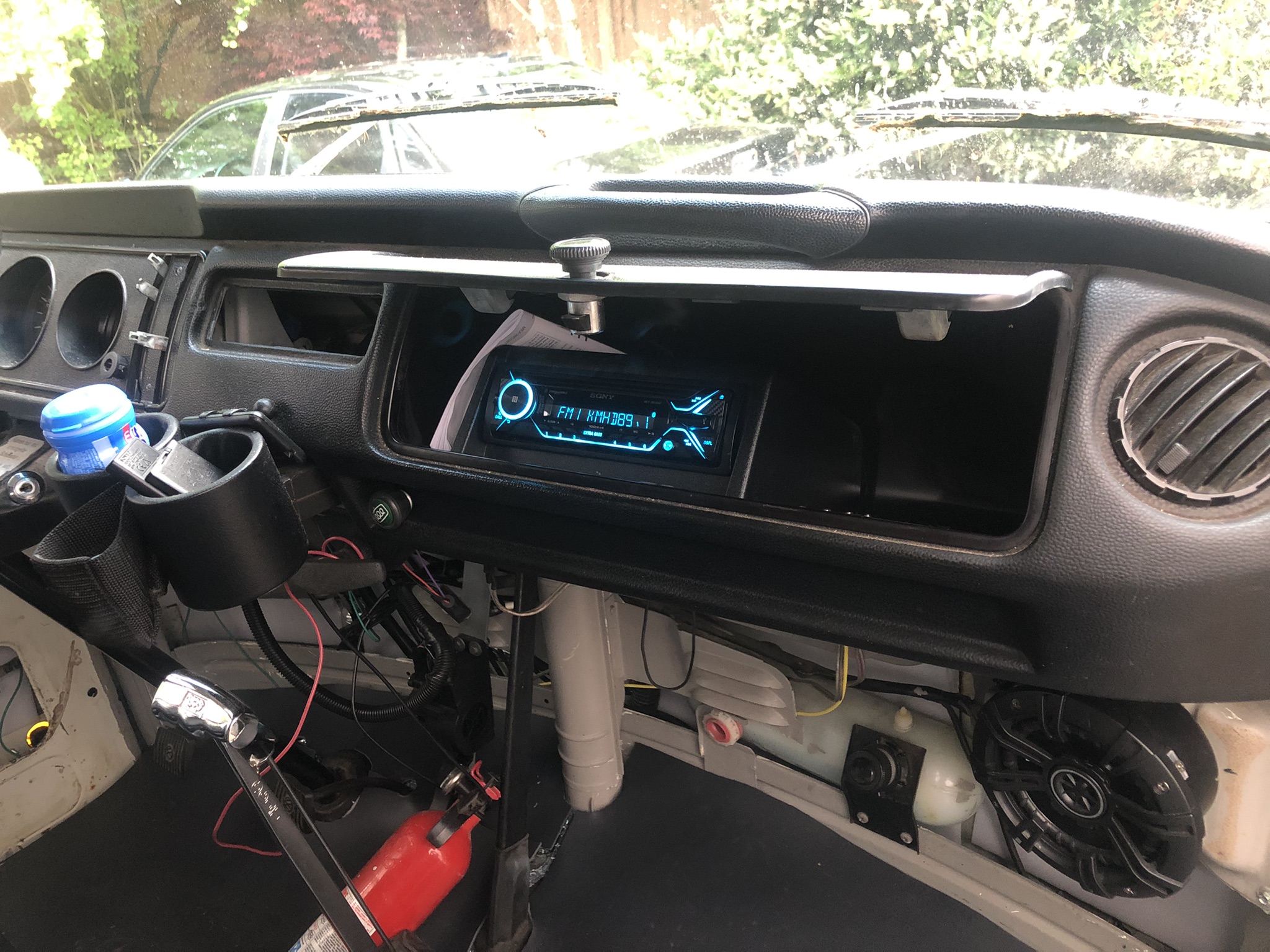
While I was working on getting sound deadener behind the original cardboard glove box, I decided to remove it for better access. I had already disconnected the luxury electrical set up for the electrical rough-in (See Ceiling Wire Rough In), so I simply unplugged the head unit that I had stashed in the glove box and pushed the plug out the hole I had bored in it. After emptying the remaining contents into a small cardboard box, I looked at the glove box. I discovered that the old cardboard box was holding on for dear life, and the removal of the support bar (Phillips screw on the underside of the glove box) did it in. The rear edge (front is front) that is pressed up against the dash had been all raggedy anyway, and once I started removing the box, that edge powdered off in chunks. So, I ordered one of those ABS plastic replacements. With the deteriorating original box in hand, I considered how I could more permanently mount the stereo when the new ABS box arrived. These were on back-order, like so many things these days, so I had to wait a while to complete this.

Solve the Head
mock-up with original box
I got a Metra Universal under-dash mounting kit (model 99-9000), and started fiddling with how that rectangular kit could fit into the rounded glove box. After several measure and test-fit attempts, it was fairly clear that hanging the stereo from the top of the box was not practical. The glove box was too shallow and the mounting kit too deep. I would have had to cut a large rectangle out of the rear of the glove box, and I'm not sure it would have fit right afterwards.

Back when I first got this head unit, I set the head unit in the glove box, on top of the molded shipping cardboard. It fit, and I could manage all of the buttons. Since hanging the box from above didn't work, I tried the kit upside down, mounting to the floor of the glove box. The kit was still too deep, but only by an inch or so. I measured, marked and cut an angle off the rear and it snugged right in. I confirmed that the stereo unit did not extend past the shortest point in the trimmed-down mount-box-thing. To mount the cut-down box to the glove box, things got interesting. I have demonstrated multiple times that I cannot manage to transfer measurements consistently. So, rather than swiss-cheese the underside of the box, I set the kit where I wanted it and marked two holes on the inside (blue tape, then a marker) of the box. I drilled out those 2 holes so I could align the rest of the box from below. I set the box such that the holes aligned and then held it in place with vice-grips while I marked the rest of the holes. Then, I drilled them out. Even then, the holes were not 100% perfect, so I expanded them where needed with a file. I added a hole at the rear of the glove box for the wiring pigtail with a hole saw and then attached the mounting kit with M3 bolts. That sentence took seconds to write, but the work took a couple of hours: tiny bolts + little finger room = patience needed.

Because, Wiring
marking holes
When I did the head unit the first time, I simply ran the power wire on the floor under the carpet. That was very Agile, demonstrated that having a stereo was a good thing, and that leveraging the luxury battery was a great call. So, since the stereo and the rest of the wiring in the bus was torn apart anyway, I changed the wire routing. Similar to the T12 front-to-back cable, I ran 2 sets of speaker cables and a power cable from behind the dash, down through the cable port behind the accelerator pedal and under the bus. I ran this collection of wiring along the frame and then found an existing factory hole (probably a drain hole) just inside of the passenger rear suspension up into the rock-n-roll bed. To keep things straight, the speaker wires were marked with tape (yellow-left, orange-right).

The yellow power wire was routed over to the driver side under the rock-n-roll bed and lightly tucked into place so it doesn't dangle into things and then integrated into the new fuse box (See Luxury Electrical Restored). Onto the speaker wires, I re-integrated the female wire connectors that I had before. One pair of two is under the rock-n-roll bed on the passenger side. Similar to the power wire, I tucked the wires under the rear edge of the bed floor so they stay out of the way. The other pair (recall there were 2 before) was sent through to the other side of the rock-n-roll bed up into rear of the formerly-fridge cabinet. Later, I may switch the female wire connectors to ports, but not today. At this point, I grabbed the floating remote rear speakers and plugged them in.

Back at the front of the bus, I integrated the various rear-speaker wires. Consider there's the pair that run up the A-pillar and to the rear over the sleeping area and the pair that now run under the bus to the rock-n-roll bed. The pair that run under the bus were the same as the pair that used to run along the floor. When I cut them, I marked them left-right. The pair that were sent up the A-pillar, however, were not. to figure out which one was which, I stripped one pair and clipped them together. Then, at the plug at the rear of the bus, I checked the plugs for continuity between the center-hole and the outer ring. One was infinite, the other was almost 0 resistance. 0 resistance is the winner, so I marked the end at the front with the same color tape (orange:right, IIRC) and then marked the other one. I spliced the remote speaker wire pairs together first, and then added the tiny wire from the stereo loom. I expect I will be adding an amp at some point, so I did not soldier them up. 

Putting it Together
note the mounting bolts
With the speaker wires integrated into the loom, the hard part was done. I spliced in ground and the yellow power wire and cleaned up the loom -to- front speaker connection. We were ready for install. The plastic glove box does not fit as easily into the dash as the old cardboard one does. I think it is a little larger, which really is fine. I needed and found a longer mounting screw (about an inch longer) for the support bar. To set the box in place, I found that suspending it in the support strap with the opening pointing up was most effective. Then, the box just tips into place. Since the box is bigger and less malleable, I focused on getting the bottom edge in the right spot, and let the top edge sit high. I sent the mounting screw home and the box doesn't wiggle at all.

I sent the wiring loom, the antenna cable and the wireless phone mic cord through the hole in the back of the glove box and plugged everything in. I took a quick glance at the fuse box and saw the tell-tale red LED telling me that I had a good circuit. Loving that fuse box feature. I set the stereo into the hole added a 10A fuse and fired up the local jazz station. After a few set-up steps on the stereo and burying the excess wire, the stereo is as complete as it needs to be for this Summer. 

So, the stereo is complete.... until I get a wild hair again to change it again. Like, wouldn't it be cool to have remote speaker plugs outside the slider so we can close the door without interrupting the music when set up for festivals or camping? Moments like this are when it is so obvious that this bus will never be done. There are always new ideas.

That's it for today. Thanks, as always, for following along-

Tuesday, June 29, 2021

Zed Body Progress

With the weather shifting warm to cold to warm again, Zed (the 1979 280ZX) work has been a little bit on-again / off-again. With the weather returning to hot for what looks like the Summer, I shifted efforts back to Zed from the other projects (you've seen the posts)... well, until this past weekend when everything came to a complete stop due to the record-setting high temps (over 45*C / 113*F). Today's post focuses on Zed's body work again, solving for the missing rear bumper and getting after some priming. Again.

Bumpity Bump
A lingering question for Zed was how to solve for the rear bumper. The original was a rusted out mess, and donorZed was about as bad. I was considering how to construct something one-off custom, but decided that an off-the-shelf fiberglass kit was a better looking, and fastest-to-implement approach. Rather than just do the rear, I got a full kit, so the front-to-back is consistent. Of course, this will delay the paint a little bit, as I have more body panels to solve for. Plus there is the added delay introduced by shipping. Ultimately, Zed will look better, so it's worth it. The kit I ordered looks like the one pictured on the side here, without the big wing on the back. That's not my style, but everyone gets an opinion. Later, I will add louvers to the rear window since that window lets in a ton of heat in the summertime if left uncovered.

In order for the rear fiberglass to mount, I needed the rear bumper bar that sits inside the big rubber ugly. I reconnected with the local Z parts-hoarding-guy to whom we sold donorZed and bought a rear bumper bar, and mounts... for about 1/2 what we sold the entire donorZed to him for. Funny how this all works. Perhaps, in retrospect, I might have saved the original rubber bumper support bar and mounts. Anyway, next was clearing the rust off the bumper mounts, and getting them ready for action. I used multiple passes with Naval Jelly followed by a coat of Eastwood Rust Encapsulator and then a coat of rattle can primer. I will shoot these with the hinges and other tiny bits that we want the color of the finished body.

Following that, I removed the front bumper support (4 16mm bolts each side) and the bumper from the supports (4 14mm nuts each side). Next, I wanted to remove the rubber ugly wrapped around the bar so we were ready for when the fiberglass kit arrives. The Phillips screws that hold the ugly cover on, however, were rust-locked in place. Multiple passes with the Kroil didn't allow them to budge. So, I had to grind them off. It is interesting how much rust was on the bumpers and how little the rest of the car had. Those front bumper mounts had virtually no surface rust on them while the bumper itself had been impacted. These mounts will also get the color spray with the other bits I mentioned above.

Prime Time
Last, I finished enough of the Bondo cycle to feel that I could lay another round of hi-build primer. The Bondo-cycle took an awfully long time, and I got far too into it. I imagine I still missed a bunch of things and it still will not look as good as a real pro paint job, but at some point you just have to stop dicking with it and go. Otherwise, you will never get to enjoy the fruit of your labor. It's just labor. I am enjoying the heck out of bodywork though, which I kind of surprising. My first round of high-build primer was both too light and mostly sanded off so if you are concerned that there will be this huge stack of paint layers, rest assured, that is not happening. I did have to wait for the weather to get warm and dry enough, though.

Once the weather turned warm again, I acted like the primer had not happened before: restoring the masking, vacuuming and blowing air, cleaning the snot out of it, etc. so it was ready to get primed. Then, I laid the body panels out under the car-port cover again and repeated the multi-passes of primer, just like I did last Fall (See Zed Prime), with a few differences. My set-up this time did not include the in-line line drier nor extra pressure regulator. I had not gotten another disposable line-drier, and without it, I could not attach the regulator. So, I set up my pressure with test fan blows on one of the fenders instead. Total Roadkill. I figured I could reduce the moisture if I kept the air compressor tank warm, so I moved it into the sun. Since the air around here is super-dry right now (humidity below 30%), there isn't much moisture in the air to get compressed into the air line anyway. This may sound sketch, but the primer landed fine.

As to shooting, I did a light first coat to give subsequent coats something to adhere to, while also avoiding runs or sags. The sunlight was so bright, it was hard to really see the fan, since the color of the primer was the same as the target panel most of the time. Similar to the 1st shoot, I did not meaningfully stop between coats 1 and 2: fill the cup, shoot the cup, repeat. Why? Because, by the time I got all the way to the end of the light coat, the place where I had started had sat for longer than the minimal flash-dry period, and it was warm enough to dry fairly quickly. The surfaces were tacky when I went around for my heavy pass, which, I felt, was just right.

The 2mm tipped gun got clogged about halfway through my 2nd coat. As I attempted to unclog it, I lost about half of a shooting-cup (or about an actual imperial cup) of paint: it turned to Jello. I think I mis-measured the concentration of hardener. Could it have been from the lack of an air-drier? I dunno. Undaunted, I grabbed another gun which had not been drilled out to 2mm; it was a 1.8mm tip. I did not clean it first, I just blew a few seconds of primer through it and got back to the job. Yes, that was lazy and yes it could have allowed for some shipping oil/crud into the primer. I considered all this and used the first little bit of shooting to second-coat the nose section that will be mostly hidden from view (under fenders, radiator support, eg). More Roadkill; maybe that show is a bad influence on me. Anyway, I finished the pieces I had not gotten with a 2nd coat after I shot some hidden areas. I found that the 1.8 tip flowed better, gave a smoother finish and had a more predictable fan than the 2mm drilled tip. So, I take from that either (a) I drilled the tip wrong or (b) my 21gal compressor, pressure set up, gun and material were all better suited as a unit to the 1.8mm tip. I'm not sure how you drill wrong, so I think the difference is really tied to my compressor, and it's ability to keep up with the air-pressure demand of the 2mm tip. Regardless, I will be shooting this high-build with the 1.8 tip on a very warm / hot day from now on.

Reviewing the Prime
None of these changes, including the especially Roadkill-inspired ones, appear to have made much of a negative impact on the primed surface. Quite the contrary, actually. I started setting up the first gun at 10 and finished spraying by 2. I took an hour to clean up work area and the second gun (first gun went into the garbage) as I let the panels sit for the rest of the afternoon. Late the following afternoon, after the panels had sat in unseasonably warm temps (30*C+ or 85*F+) most of the day, I did some test sanding on the mostly-hidden areas with some 320 grit paper. The primer powdered smooth very quickly. If this is any indication, then this priming session was much better than the first. Perhaps this high-build poly-primer is more temperature sensitive than the Eastwood folks indicated on their site: warmer drier days are much better. The first time around (when it got into the lower 50's*F/11*C overnight after shooting), there was meaningful stippling on the surface. This time, when the overnight temps barely got below 70*F, the surface is much less dimpled. And, it sands smooth much more easily; like, a few passes with 320 and it's smooth. Last Fall, I tried pre-warming the panels inside my garage but that had no effect: the shell which sat outside the whole time had the same little dots peppering the surface. I think the real difference was the long warm days both the day of and after shooting.

Learnings
My big take-aways from the shooting the hi-build poly-primer from Eastwood: use a 1.8 tip and an in-line drier on a warm-to-hot day when the overnight temp will not fall below 18*C or 65*F for best results. Do a quick-coat first for the next heavier coat(s) to adhere to. Last, it is a good idea to have an extra gun as an emergency fall back in case you mess up the hardener concentration and jack up your gun in the middle of your spray-sesh.

Go Forward
Next, I will be sanding the rest of the body panels. Then, once it arrives, I will be handling the body kit. At some point, there will be paint, but I may shoot a urethane primer/sealer first (once Eastwood has it in stock and ships it to me). And, of course, the body kit will probably need some tweaks and then priming. I sincerely hope I can get it all done before the weather prevents it. While the Fall rainy season is a distance away, we cannot guess whether we will be revisited by toxic smoke again, scrapping late-Summer plans. For that matter, we are having triple-digit heat waves (40*C+) that are keeping me penned inside as effectively as the smoke did last summer. 

I expect that if I have to wait too long for the body kit, I will set up and shoot the parts that will not be impacted (like the underside of the hood, the hinges, the bumper mounts, etc) so I can make some headway and save myself some shooting time later while also getting a better feel for the equipment and material. Some of this stuff may not be terribly post-able, but I will try to at least put a little message here about the work.

Thanks, as always, for following along-

Tuesday, November 12, 2019

TDI install retrospective: Physical Mounting

Continuing the process of back-documenting what I did to put a TDI engine into an old (1972) air-cooled VW bus. Today I cover physically attaching the engine to the bus. This may sound simple, and if you only saw the end result, you might still think so. That's the beauty of what Hal built. Elegant in it's simplicity.

Transaxle Mounts
early mount attempts
The stock bus has three mount locations for the engine/transaxle combo: the front of the transaxle, the bell-housing in the middle and the "mustache bar" near the rear. I decided to reuse the transaxle mounts without modification. The transaxle wasn't really getting modified, so it should just fit. And it did. There were some who questioned the vibration through the mounts at the bell-housing, though. I believe there have been experiments by others where the bell-housing mount was eliminated, but I have also heard that this put stress on the output shaft and other components because all of the weight was being handled on the ends. Looking at the front-most transaxle mount, I'm not sure it really should hold up more weight than it was originally designed to hold. Your bus; your choice. Now, years later, I am fairly convinced that the bell-housing mount holds most of the weight of both the transaxle and the engine.

Motor Mount Attempts
bar to rear frame, 1st model
I looked at and tried a few different things to mount the engine. First, we tried building mounts that would attach to the sides of the engine to threaded bolt holes that were unused in the stock vehicle install. These bolt holes were on the block for industrial applications of the engine so, they should have been stout enough to do the deed. The idea was to reuse the original bolt holes for the mustache bar. The holes in the block and the mustache bar didn't line up very well and since the plan didn't include anything to absorb vibration, the bus would have shook like a paint mixer. I tried to accommodate this issue with some vulcanized rubber mounts, but it looked complicated and not terribly strong. So, I threw the whole thing out, and got to talking with Hal about it.

box being developed
Hal knows bus. He recognized that the rear bumper brackets are held to the bus with thick carriage bolts to the rear frame. The same rear frame that the mustache bar attached to, just more rearward. We figured that if we leveraged the mustache bar concept with a thick, straight bar between the bumper brackets, we could re-use the stock TDI passenger-side motor mount. To the right, here, you can see an earlier version. Hal and I agreed that something less complex would work.

Motor Mounts
Seeking something simple, we started with a piece of 1" angle-iron, onto which we marked and drilled holes to align with the bumper bracket holes. The bracket was then bolted to the rear frame so a straight bar could be measured, cut and welded on. Bar done.

Then, Hal welded together a simple box with a central support that would join the mount to the straight bar with bolts. The whole thing bolts together: the bar to the frame (re-using the bumper bracket bolts), the bar to the box (with a basic bolt-nut pair) and the box to the mount (again with a basic bolt-nut pair).

I have removed and re-installed the engine both with and without the transmission numerous times. This part of the system is a total non-factor in the process. I have also removed the rear bumper a few times independently of the motor mount, and while it is slightly more difficult than before, it is not really impacted: I simply support the bar with a floor jack, remove the 4 bolts (2 per side), remove the bumper, put the bolts back in and lower away the jack. Super simple. Of the things that were done for me for this build, this is the single greatest contribution. I said it then, but haven't said it enough since: THANK YOU, Hal. You really crushed it.

Measurements of the straight / cross bar:
length of main span, from bracket to bracket: 42"
angle-iron "bracket" depth (front-to-rear): 6"

Measurements of the box:
across the top: 9"
height: 7.75"
space between vertical bars: 3"

Prior related posts:
Preparation
Fuel System

Next related posts:
Vacuum System
Air, Intercooler and Exhaust
Primary Electrical
Cooling
Secondary Electrical
ECU, dashpod and Sensors

Wednesday, January 28, 2015

Prepping for Paint

While working on the windshield washer effort, I got to thinking about the paint on the front of the bus. Those 2 tiny nozzles were original as is the paint on most of the bus, and the paint is in about as good a shape as those nozzles were: barely functional. So, once I got the washer bits done, I resolved to getting the paint looked at and decided that I was going to prep and paint the nose.

Organization is Key
headlight can rust
from 12 o'clock to 5
One thing that John Muir was always harping about was the need to properly tag and bag your bits an pieces. I wholeheartedly agree. No matter how optimistic you are about spending every spare moment on your project, things come up. There's a Bruin game on tv or there's a freak snowstorm you want to go play (or have to work) in. So, as bolts come off, collect them into zip-lock baggies and write with a Sharpie on the bag what the bits are for. The only exception to following this religiously is when you can thread the bolt back into its originating location (bumper bolts, eg) where they won't get in the way, or lost.

Beyond the baggies, the parts I removed needed to be categorized. Some things, like the front bumper, don't need any additional work done to them except maybe a soap-water wash or a polish. Others, like the headlamp cans need to be rust sanded, primed and painted. A final pile was created for those things which just needed to be replaced because they were beyond rust repair or a replacement was less expensive than trying to save the old part.

Removing the Bright Work
turn signal during removal
I love that British phrase for what we colonists call "the chrome pieces". Bright work sounds so much more refined. Rather than tape off things, I chose instead to remove everything and go deep on rust while I was at it. The front bumper goes first with 8 bolts: 2 each under the doors and then 2 each on either side of the belly pan. I'd hand-painted it with white rustoleum paint (see Front Bumper part 4) about a year ago. It held up okay, but the white looks dirty already. I guess I should have washed it more often. Regardless, I set the bumper into the back of the bus to start the wash/polish pile.

Once the front bumper was off, I pulled the headlight surrounds (one Phillips-head bolt and it pops out), headlamps and the cans. The original cans have rust spots on them, and the body cavities where the cans reside have a little too. Considering the bus is 40+ years old, I thought that was a really good sign. The headlight surrounds went with the front bumper. As I pulled the cans out of the nose of the bus, I labeled which side each can came from. I separated the bolts and spring and put all of that stuff into a single headlamp baggie. The cans started the rust treat pile. Next, I removed the front turn signals. The lenses are good, but filthy (clean/polish pile) but the housings were spotted with rust. I simply touched the reflector with a finger and it started flaking off. So, the turn signal housings started the "replace" pile. The housings were then joined by the fresh-air vent intake: rust appeared on the back/inside, and a replacement is available at busdepot.

stripped of what could be removed
and the sanding started
The last thing to remove (in my case) is the spare tire hanger. Held on by 3 thick screws, the tire mount appears more universal than I'd realized. It had a dusting of surface rust / patina in a few areas, but, again, it was in great shape for its age. Clearly, it wasn't original, though, as I found a sloppy peace sign had been spray-painted on the nose prior to the tire mount being installed. The tire mount went into the rust treat/paint pile and the screws into a baggie.

Now, the nose is ready for paint. Except... the windshield is still in... and won't it look funny if just the nose is painted, and the doors that match up against the nose aren't? The story continues next time.

Sunday, March 16, 2014

Front Bumper (part 4)

As much as I wanted to run a full test of prep and paint on the bumper, I simply ran out of patience.  Today, I'll wrap-up the bumper through install.  I may return to it while on-bus, or even pull it to finish later, but I gotta get behind the wheel and drive it again.  There's a zen or inner calm that comes with steering an old bus that just isn't reproducible in anything else.  It's been too long.  On the shortened completion.

Final Wet-Sand
assembly supplies for 1 step
The paint was finally ready for wet-sanding after a full week of drying.  The $50 paint job guy talked about how thinning the paint would shorten the dry-time, but the articles I read didn't call out the more obvious: if its really cold, no degree of thinning will help Rustoleum cure faster.  I think the curing really took the warmer weather (low's above 40*F, high's above 50*F) to settle in and be present for a week.  Like the prior wet-sanding adventures, I used a bucket of soapy water and worn 600-grit sandpaper.  Unlike the primer, though, the thinned paint didn't dust as much.  The 600 grit took out most of the brush marks pretty quickly.

Final Paint
I decided that I over-thinned by going 1/2 and 1/2 paint and mineral spirits the first coat, so I thinned 2/3 paint to 1/3 mineral spirits for the second coat.  I also heated the garage with a recirculating oil heater before I started.  Just be bringing the ambient temp (and the surfaces to be painted) up to closer to 70*F made a very big difference.  The paint didn't run nearly as much, covered a little better, but the thinning held the brush marks at bay.
If you do this, remember two key points: first, always keep a wet edge.  If you try to cover such a broad area that you find yourself applying paint into paint that has become tacky, your paint will not cover right.  Always apply into wet paint.  Second, if you're using a brush, draw your paint-loaded brush from the unpainted area into the already applied wet paint.
While still drawing the brush horizontally across the surface, pull the brush off.  This will minimize brush marks from forming in the first place.
seal held w/blue tape

Redirection
The paint was hard and dry in a few days, but I chose to not color sand.  Rather, I decided that I'd been without the bus long enough.  At some point, I'll do the wet-sanding, and polishing.  In fact, I bought all the needed supplies (1000, 1500 grit paper, polishing bonnet, polish) and a cheap polisher at Harbor Freight for when that day comes.  I figure I'll practice on the bumpers before I try it on the main body.

Bumper Assembly
The early / low-light bay has a 3-part bumper: the main bar plus a step that wraps around to each of the front doors.  The step bolts to the bar with 3 bolts, and a simple seal runs in-between.  The seal fits around the end of the bar with the long edge running behind (rear-side).  When I removed the old seal, it was clearly held firm by the bolts.  Re-assembly is tricky with a single pair of hands, though possible.  I held the seal in place with blue painter's tape while I set it in place with the bolts.  I strongly suggest getting the replacement bolt set from Wolfsburg West.  It made reassembly much easier and the finished product look much better.  Unfortunately, the 1972 bumper steps are held to the body by 2 bolts a-piece and the bolt kit only provided enough for one bolt each.  I will be buying 2 bolts at the local hardware store, but otherwise, it was just what was needed.
rubber step button and tab
The rubber steps go on in the reverse of how they came off.  If you're like me, you probably didn't exactly remember how that went.  First, slide the 4 square tabs that run along the outer edge into their corresponding slots.  From the inside, pull them all the way in with a pair of needle-nose pliers.  Then, wrap the step over the step and press the round buttons into the corresponding holes.  But don't do the one closest to the rear yet.  Next, pull the front edge of the inner lip over the inner edge of the step.  By sliding your finger along the inner edge of the lip, the rest of the lip will seat, until you get to the rear point.  There, you will need to pull that corner out and around the inner lip as well as the corner where it meets the outer edge of the step.  Once you've gotten that around, press that last button through the hole.  It looks sweet, eh?
Once the steps are bolted to the bar with the seals and rubber step in place, we add the frame mounts.  I mentioned in the last post about the appearance of rust where the mounts met the bar.  To reduce the probability of that happening again, I dug into my plumbing supplies and grabbed 4 orange sink washers.  I put the washers around the bolts, between the bumper bar and the frame mounts.  Once the nuts were torqued down, it had no impact on the location of the final mounting or the find-ability of the bolts-to-holes.
sink washers between
frame and bumper

Bumper Install
I would recommend finding a friend to help for this part, if you haven't been able to sucker anyone into helping you yet.  My kids were all playing on their skateboards, and Boo was sleeping off an early morning shift, so I was on my own with my radio.  I set plastic tubs under the spots where the steps mount to the bus frame and carried the bumper assembly over.  I placed the bumper against my quads, squatted down while holding the frame mounts so it wouldn't bounce off the deck nor the front of the bus.  Fun.  I set the steps on the plastic tubs and slid the bumper into the general location.  Then, it was a matter of holding the bumper in the air with one hand while lying on my side and fingering-in bolts.  It was important to get the bolts in just far enough to hold the bumper up so I could make sure it aligned properly.  I then moved to the step-bolts, and threaded them in part-way.  With a tape-measure, I confirmed that the bumper wasn't crooked and tightened the bolts down.

Last, install your license plate, and you're done.  I will be getting new license plat
e hardware so it matches the rest of the new stuff.  The old rusty nuts, washers and ugly bolts just seem out of place with the rest of the bumper.  Truth-be-told, the rest of the bus looks a little out of place with the nice bumper.  Or, maybe, the bumper looks too nice to be on that bus.  There's clearly something not quite aligned.  Anyway,  I still have to solve for the smashed tow-hook (I kinda forgot about it), and finish the 100%-ing of the bumper anyway.  I can say, though, that I can now see every blemish on the front of the bus.  Great.... :)
That's it for today.  I intend to ride the bike or drive the bus to work tomorrow, weather depending.  It seems wrong to hope for rain, here where the rain seems like a constant, but I'd really like to get the bus into the daylight.  Thanks, as always, for following along.
mounted and ready to go


Monday, November 23, 2009

Radiator mounting planned

I was fortunate to get a couple of hours on Sunday with limited distraction, so I rolled under the bus between showers and I believe i have a plan for mounting the radiator under the bus. I ran out to Lowes, got a bunch of hardware, and started what I believe to be the final run on the brackets before installing this beast. Most of today's post will deal with that. I have no further news about Tom or Marianne. My wife will be traveling to visit with them in a few weeks, so she'll dig up what's really going on when she's there.

Concerns
One of my lingering concerns about mounting a radidator under the bus is that it will be subjected to road debris abuse. Beyond just simple plastic bags, and gravel, there can be large obstacles in the road. I've seen mattresses, sheet rock, lumber, a ladder, etc, all in the last year on the Oregon highways. Add to that the ice and snow that we got last winter, where my Jetta was getting high-centered by the mid-road snow pack, and I think the concerns are justifiable. I have looked at many designs by different people, and they seem to fall into 2 categories: avoidance and strength.

Avoidance
The under-mount radiator designs that follow this pattern are purposely placed as flat as possible, and as close to the floor of the bus as possible. These achieve some degree of safety because the debris can't really get to them. The downside of this design is that the air can't get there naturally either so any cooling is done exclusively by fans. This puts considerable pressure on the system working correctly, leaving little margin for error for a failed fan. Some kind of fan monitoring should be used to indicate when the fans are on / off at the dashboard so the driver can know when the fan(s) has failed.

Strength
The under-mount radiator designs that follow this pattern are angled to catch the air, and have a cage of sorts around the radiator. This cage deflects debris from getting to the radiator, in theory. I would think that there is the possibility of high-centering or having the entire thing ripped off by passing debris, if the debris is something like a tree stump or some other non-movable object. These do have the benefit of naturally grabbing some air on its way by, so they can operate with some success if a fan(s) fails.

Flexibility
This is the pattern that I'm going to try. It is a take on the strength pattern, but allows for travel within the mounting so that the radiator mount can partially absorb, and partially avoid debris. This pattern should allow for natural air passage and the use of fans like the "strength" pattern, but with the ability to move up and down if a tree stump or other immovable object is traversed.

Implementation
First, I made the bracket relatively simply - it is just a simple "c" wrapping each of the 4 mount points on the radiator. These "c" wrappers then tied into one of 3 brackets - one for the front and 1 for each of the 2 rear. The front is a basic square tube the should assist in the strength of the front bracket while partially obstructing the temperature sensor from direct contact by flying debris. I covered this in previous postings.

To these brackets, I have attached eye-hooks. These eye hooks will connect, through chain, to eye-hooks that are connected to the cross-members under the belly of the bus (the point at the cross-member will be re-enforced with some extra steel). This chain will add the flexibility to move. To prevent the radiator from bouncing up into the floor of the bus, I will add a rubber travel-stop (think snubber from the front end). I will be able to vary the depth of the angle of the front end by adding or removing chain links. I have selected chain and single-links that can handle up to 450 pounds. Anything less seemed too thin and anything more seemed excessive.

Protection
Across the front bracket, I will attach a larger round pipe (like a 16" stretch of fencepost). This will serve as a bumper that will absorb the initial contact with the immovable object and cause the front lip to bounce up - at least that's the theory. Behind the post, I'll put in a security screen style grid to prevent larger rocks from getting past and into the radiator area.

Shrouding
Last, surrounding the floating radiator, I will put a small cowling / shroud. This will help guide the air to the radiator and keep the rad-heated air from recirculating when at a dead stop. This shroud won't be more than a half-dozen inches tall. If it were much taller, it would prevent the movement that the chain is allowing. If I can figure out a clever way, I'll curve the shroud so it rounds off at the top. This would allow the shroud to be taller. Regardless, it needs to be removable so I can get to the chain for maintenance.

That's it for today. I was able to get started on the eye-hooks, but I ran out of bolt-nuts, and daylight. I need to stop at the hardward store for lock washers and nuts. I doubt I'll have much more time before Thanksgiving to work on Hapy. I may not get any time on him for another week, actually, so, I won't post until after the holiday. Happy Thanksgiving, and thanks for reading.

Pictures:
top - the rear brackets with the eye-hooks attached. The long eye-hooks will go into the thick cross member in front of the transaxle
bottom - the front bracket with the long eye-hooks attached. These will be connected via a chain to one of the shorter cross members (which will be re-enforced / backed with some steel at the mount point)