Tuesday, April 28, 2020

Oil Pressure and Temperature (Part 2)

In my last post about adding gauges, I suggested 6 possible alternatives. Today, I focus on the viability of option 5: fitting a Porsche combination gauge into the spare hole in the original bus dash pod. I do want to stress that I bought pretty much everything for this project before the end of January, before we knew what this CoVid-19 thing was about. The only exception is the oil temperature sensor. I had purchased the wrong one (English threads not metric) long ago so I needed to get one that would actually fit. On with the post...

Porsche Combo Gauge
blank held up by napkin-holder
First, we start with the question I've been dying to find the answer to: will a combination gauge from a Porsche fit well enough into the third hole on the bus dash to provide oil temp and pressure information? The short answer, I think, is "yes". I'll pause for a second to let that sink in. Yes, that gauge will fit. But, will it look good and do we need to do anything to the dash or the gauge or both to make it fit? Ay, there's the rub. In this case, quite literally... there's a rub. As in, the left-most edge of the combo gauge rubs against the large plastic column in which lies the speedometer. Could it get wedged in good enough? Sort of, but it would look pretty janky. So, could we shave off some of the outer edge of the combo-gauge to make it fit? Maybe. Alternatively, we cut a small section out of the plastic column, and have the combo gauge nestle into the small section. Either way, something needs to be damaged to further the investigation.

almost exactly 4" diameter
the original blank 3-5/8"
So, what's to do? Well, it turns out, my dash-pod, dash board or whatever you want to call the plastic thing that is held on with 4 screws, is cracked. In fact, there is a break running from the bottom edge of one of the climate control sliders all the way through the bottom of the dash-pod. And, the upper left corner is broken off. Cosmetically, it really should be replaced, but it does hold to the dash, and hold the gauges well enough. When I contrast it against the nearly flawless Porsche combo gauge, it seems rather obvious to me which one should be sacrificed to learn how to make it fit... or if it can fit: the cracked and flawed dash.

Before I start pulling out the dash, it would be wise to take a bunch of measurements. I took pictures of them so others can see how close everything is before I touch anything. This includes a test fitting in the cab of the bus. The pictures are strewn across this posting.

Pull the DashPod
combo gauge with glass
from blank on top of it
The dashpod is held on with 4 long Phillips screws. Remove them and stow them safely. Then, reach behind the dash and un-thread the speedometer cable from the speedometer. If you have the plastic tips on your climate control levers, remove them. Now, you can lift and tilt (top downwards) the dashpod so you can get to the wires behind. I can't stress this enough: do NOT just start pulling wires. Identify each one and label it with a toe-tag, a piece of folded over tape, whatever it takes so you can correctly put it back in at the other end of this exercise. Move slowly, be patient. The slower you go now, the more you will appreciate that you took the time at the other end. Once all of the wires have been individually labelled and removed from the back of the dashpod, you can remove it all the way by sliding it towards the center of the bus.

Measure, Check, Measure, Check then Cut
Even though this dashpod is cracked and will be replaced, I have no idea when I could get a replacement. Worldwide commerce is slowing to a crawl, my favorite parts places have been sending notices that they are shutting doors until further notice, etc. So, even though I expect to replace this dash, it could be months before I find a viable replacement. So, I will treat this exercise as if this is the only dashpod in earth.


test fit cockpit side
test fit from "above"
The picture on the right, here, shows where the interference points are. First, at the bottom of the photo you can see that the black ring around the Porsche combination gauge hits the side of the speedometer section before it can fully settle into place. This uneven look can be seen through the rear (front-is-front) of the dashpods in the picture on the left. It may not be obvious, but the oil pressure gauge is slightly less visible than the oil temperature gauge. The two idiot lights should be in the exact left-to-right center of the circle, but they are offset to the right. What cannot be easily seen from any picture is that the edge of the gauge hangs up on the little plastic tang between the threaded hole for the screw and the edge of the gauge hole. I started with those: I cut a shallow channel in-between with a hacksaw.

hole cut in speedo side
trimmed backing
Once I could get the gauge to settle in, I could mark where to cut into the speedometer slot. I covered the area with blue painter tape and marked up ideas with a sharpie. The hole ended up less than an inch from gauge top to gauge bottom and less than 1/2" in depth. It is oriented just below the edge of the outer gauge ring so the combination gauge can slot in. Ultimately, the gauge does not need much space, but it needed a little.

Last, the metal backing plate on the original dashpod needs a trim. It is not as obvious in the picture, but that slight overhang is enough to knock the combination gauge off-center. I marked the short (about an inch long) stretch that needed to be removed along the edge. With tin-snips, I cut that section out and then refined it with a file until the gauges could nestle together. Now, the backing plate threads back on without pressure and the combination gauge sets perfectly centered.

Gauge Wire Identification
labeling wires
If you are thinking of doing this, I strongly suggest that you verify the combination gauge you acquired still works before you grab a saw. I found this kind of fun. The gauge that I was shipped was removed from a late 70's Porsche and then the wires were cut. This is important because I would have had much more research to do had the seller pulled all the wires off. Now, there was a strange green over-spray on most of the wires, so my identification instead was based on what they were plugged into. Similar to the wires removed from the old dash on removal, I labeled these wires as well. There were 2 circuits of particular interest: brown and blue with green dashes. These were the ground and switched 12V respectively. These 2 circuits wired multiple things together, and in the case of the blue/green wire, it had 2 open ends. I think that is to prevent one failing gauge to eliminate the viability of the other. Once these were identified, the signal wires for the various gauges and idiot lights were easy to identify. I removed the gauge lights, after I demonstrated that the ground wires were also grounding those light sockets.

Validating the Gauge
testing oil temp gauge
Now for the fun part: testing the gauges. I grabbed an extra deep cycle battery I had in my garage, and set it on a grub-towel on my kitchen table. My wife loves me. To the positive side of the battery, I connected one blade of a 3-amp bladed fuse. To the negative side, I connected a 16ga blue wire and connected the other side to the ground wire from the gauge. I took a long 16ga yellow test wire which had a female disconnect on one end and bare wire on the other. The disconnect end fit properly onto the open blade on the fuse. I touched the wire to the 12V switched and the gauge clicked, sending the oil pressure gauge to the top. I figured this could be a bad thing, but, undeterred, I removed the wire from the fuse blade and went looking for my senders. I figure this behavior could be a way to signal the driver that there is no longer any signal coming from the oil pressure sender, since I did put the power on the oil-pressure switched 12V side.

combo-to-speedo "front"
I started with the oil temperature, after that odd reaction the oil pressure gauge had to power applied. To simulate installation, I ran another ground wire from the pre-existing blue one around the threads of the sensor. I then ran a jumper from the sensor signal to the temp gauge input. When I applied 12V to the switched circuit, the temperature needle moved off of the bottom post. It wasn't much, but that told me it was reading something. Considering that a success, I did the same thing with the oil pressure sensor. This time, instead of leaping to the top of the gauge, the needle lifted just a hair off the bottom post. Again, I took that to mean success.

I am concluding that the modern VDO sensors will activate the original VDO gauges. I need to conduct further tests, but this post has already gotten really long. I'll post on those tests next time. And, I'll post what the gauge looks like after all the trimming.

Thanks, as always, for following along. I must admit, if you are looking for a can't-leave-home project, this one has been a lot of fun. Please stay safe, and more next time-

Tuesday, April 21, 2020

Oil Pressure and Temperature (Part 1)

While working on the TDI install retrospectives, it occurred to me that I did not have visibility into the oil system. It bothered me that I did not even have an idiot light to tell me my oil pressure was too low. So, I started working through how I could solve. Today's post starts us on that journey. I started this before the winter holidays, but I'm only really getting down to it now. I had a significant Paulie Axiom event this past week that reminded me of this old post. The Axiom still holds true; I have new examples almost every week.

Sensing
VDO 360 006
It starts with collecting the oil temperature and pressure information. As I mentioned in the final retrospective (See TDI Install Retrospective: ECU Dashpod and Sensors), the pressure sensor in the oil filter housing does not send an "honest" pressure. It somehow sends a relative pressure, so you can't just tie into it for a gauge. I don't want the ECU to freak out because there isn't a pressure signal either, so we need to find a good spot. Our friends on TDIClub (RacerTodd, specifically, on this thread) have located a good spot for collecting the oil pressure and temperature from the oil filter housing. In the picture at the bottom, nicked from that thread, the yellow circle is the spot. The thread size, according to him, is M10x1, which aligns with the thread size/pitch of a standard VDO sensor.

So, with this information, I collected (in late Fall, 2019):
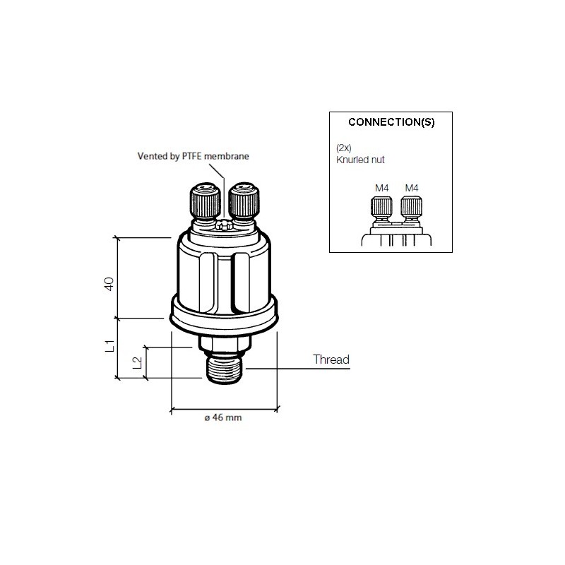
VDO 360 006: oil pressure sensor with the dual idiot light (7psi trigger) and gauge posts,
VDO 323 423: temperature sensor (300*F/150*C Max),
VDO 323 088: temperature sensor (250*F/120*C Max) and
VDO 240 850: sensor splitter / adapter so 2 sensors can run out of one spot

I am concerned that I need an adapter because the temperature probes are so long that it would bump up against something inside the oil filter housing. We'll see. Just in case, I had a sensor that was 1/8npt thread so maybe I can figure out an adapter instead. I also got a shorter sensor that tops-out at 250*F/120*C. I'll get to the sensor stuff later.

Wiring
note unused spot to right of speedo
AND a gauge where your right
knee would be. Huh?
I had intended to run one thick cable from stem to stern for all of my not-typical-bus wiring. Then I considered each circuit individually. This led me to a different decision: 2 thinner cables. Here's why: In the ECU Dashpod, etc posting I linked above, I listed out a number of circuits. Many of these wires run from behind the dashboard (or at the foot pedal) to the spare tire well at the very rear on the driver side. When I add in the desire for idiot lights and a couple of gauges, the number of circuits grew by 5 or 6, but none of them went to the spare tire well. They all ended in the engine compartment where the sensors were. So, rather than plan for a thick cable of, say, 20 wires, I can split that effort into 2. First I will focus on the 6-wire cable that will deliver the signals for the oil temp gauge, the oil pressure gauge and the oil pressure idiot light. Eventually, it will also deliver an Alt idiot light and a low-water idiot light. I'll leave the last wire open so I have it available for something I haven't thought of yet. I'll post on the snaking of that cable after it's done. Depending on the weather, maybe that'll happen soon... or in mid-July. Love those wet Oregon springs.

Gauge(s)
Last consideration is the gauge or gauges. With VDO sensors, VDO gauges are the logical choice. Buses delivered with VDO stuff, so this is staying consistent with original intent as well. Most bay window buses have a blank spot on the dash to the right of the speedometer. Some folks have retrofit a clock or a tachometer in there. Mine is the standard blank plate held on with 2 8mm screws from behind. The visible space within this hole is about 80mm in diameter. A typical VDO gauge is 2-1/16" (52mm). Simple math says that 2 52mm diameter gauges cannot fit into a single 80mm hole. So, I thought about how I could get creative.

which one is the altimeter?
Creative idea 1 - have the lower half of one of the gauges hidden under the bottom of the ring. This sounds great in theory, but the 8mm screws which hold things to the back of the dash are located at 12 o'clock and 6 o'clock. The 6 o'clock one would prevent any gauge from hanging below like that. I considered setting it off to one side that way, but in order for the housing of the gauge to clear the screw, it would be oriented at 4:30 or 7:30 and look real janky. Plus, the upper gauge would be pushed so far up, the top edge of that gauge would not be visible. So... idea FAIL

Creative idea 2 - get one of those 2-gauge housing things and set it on top of the dash. Okay, this isn't terribly creative. Quite the contrary, this is the obvious idea, but to me it looks so bad. Just look at the picture above. I mean no offense, but the aesthetic just isn't there for me. Currently, my dash top is clear. If I were to add one of those, it would meet the need, but I think the looks would bug me every time I got behind the wheel. Beauty is in the eye of the beholder...

classic 2 gauge housing
Creative idea 3 - get one of those 2-gauge housing things and attach it to the lower front of the dash facing up. To give you a better idea, consider that when sitting in the driver seat if you were to look down at the steering wheel and look through it, you would be looking at a warning sticker attached to the steering wheel support. If a gauge housing were placed there, it would be relatively easy to mount, easy to see and it wouldn't get in the way of driving nor your legs, unlike the first dash picture where the gauge is right where your right knee would be. This was the leading candidate until I had creative ideas 5 and 6.

Creative idea 4 - get one of those 2-gauge housing things and attach it to the shelf up where everyone else has sun visors. The problem with this one is that the space between the shelf and the ceiling is too short to fit a housing, so it would have to be attached with just a simple ring-mount. They are not pretty, but would work. I would also have to route the signal wires plus the illumination power up there from somewhere. The extra wiring would prove difficult to hide, further detracting from the aesthetic.

part number 911.641.103.x
Creative idea 5 - get a Porsche combo gauge and fit that into the spare hole. "What's that," you ask. Porsche has VDO gauges stock just like the bus does. They have a 100mm diameter dual gauge that has the oil temp and pressure as well as integrated idiot lights for the alt/generator, and oil pressure. Some of them also included a brake warning light. These run for over $125US on eBay. The biggest problem with this idea is the overall size. If the gauge is 100mm but the hole is only 80mm, then we lose 0.4" in radius, which may effectively block the visibility of the outer edges of the gauges, just like in creative idea 1. There exists an 80mm version of this combo gauge, but I have been unable to find it used, and new it is, like, $325US (well, it is a Porsche part), so that's not going to happen. I don't think this size was produced for many models nor years.

Creative idea 6 - get the participant bits of a Porsche combo gauge and make your own. This sounds a little nutty, but hear me out. If all I need are the 2 small gauge bits, and I can eliminate the extra space between and around the 2 gauges, perhaps I can assemble a combo gauge that fits. I don't know about idiot lights, but first things first, can just the 2 gauge pieces fit? I mean, somehow the Porsche and VDO people figured out how to make one fit into 80mm, and I sincerely doubt they made special one-use gauge innards to fit that slightly smaller footprint. Considering what this guy did, my idea is not that far-fetched. He built his own multi-gauge from the working innards of off-the-shelf VDO gauges. Very cool.

---

nicked from TDIClub
If you've read this blog for any length of time, you know I have to try ideas 5 or 6. Could it be more expensive and ultimately look worse than any of the other options? Absolutely. Could it possibly not even work, forcing me to do one of the other options? Most definitely. But it is this kind of thinking that got the TDI engine into the bus in the first place. So many people said that couldn't be done, or it was a bad idea or that the engine couldn't withstand running at whatever RPM or putting a water-cooled engine into an air-cooled bus was blasphemy. I was even told to sell my bus to someone who would appreciate it and go buy a mini-van or a Sprinter. blah, blah, blah.

So, while we were just learning about some new virus discovery in China (not a dog whistle, just saying that as a reference to a point in time) and a possible first case in the US, I bought one of these Porsche combination gauges off of the UK eBay site for less than $125US delivered. I will see how it looks in the blank spot before I start removing the individual gauges and update as I go. Unfortunately, the VDO folks don't know much about their old no-longer-available gauge components like these, especially when they were built specifically for a car manufacturer. I direct messaged with their staff, and that was fruitless. So, while the old Porsche/VDO combo gauge may look the best, supporting it long-term will be difficult. Ultimately, I may either have to go with one of the other options or build my own out of widely-available VDO gauges that I tear apart like that 914world poster did. I have both an oil temp and an oil pressure from VDO sitting in my garage from back when I had the original engine, so going that direction would kind of be free. Just time consuming. Here's a PDF describing a few gauge-cracking methods if you want to give it a try yourself.

Thanks for following along, and if you have any suggestions for other ideas, or opinions on the ideas I've floated, I am absolutely open to hearing them. I just have to try idea 5 first.

Tuesday, April 14, 2020

Oliver Gets a Cat (Part 2)

This is still not a children's story. Instead, today we finish integrating a catalytic converter into the Bell header-through exhaust system I installed onto our 1978 MGB, Oliver. Since my last post, I have learned that our Summer Solstice music festival, 4Peaks, is cancelled this year. While not surprised, this summer will be our first in years without a trip in Hapy to see some music. Yes, that is a total first-world problem and others have far bigger issues to contend with than some music festival. Gotcha. It is still disappointing for me, my fellow patrons, the vendors, the hosts, and the musicians. Anyway, where was I?

Pipes Arrive
I mentioned last time that I got a replacement section of pipe shipped from Britain. I measured, re-measured, etc that pipe and cut it into 3 pieces, 2 to keep, one to toss. After test-fitting those 2 pieces, I shipped them off to the ceramic coating company I used 2 years ago. The owner got the job done and the pipes shipped back fairly quickly. I had read that CoVid-19 can reside as an active virus on cardboard for up to 24 hours (and steel and plastic for up to 72 hours), so I set the box on the floor of my garage and let it sit for a few days. Once out of quarantine, they were ready to install.

Heat Shield
One of my biggest concerns about this whole project was how to keep the heat (up to 800*F) from cooking my legs on long drives. The MGB originally delivered with a heat deflector that was integrated into the floor, but mine was cut up as part of the floor replacement I did the summer after I got him. I looked into commercial heat shields, but they are awfully expensive and they are generic enough you need to trim them with snips, etc to get them to fit. Next, I looked into fabricating one with a few rectangular sheets of aluminum and a thin sheet of high-heat insulation. I constructed a fairly good model with cereal-box cardboard (one of my favorite modeling mediums), and was just about ready to take that leap when I found the HeatShield family of products. I decided that a known solution was a better choice than my experiment, especially when it came to temperatures that high. Their solution would cover 90% of the catalytic converter. This does not eliminate my concern about accidentally setting tall grass on fire if/when I parked on the side of the road or at a more rustic setting otherwise. Since the ride height of this sled is around 6 inches anyway, the honest truth is this car will not be going anywhere near tall grass. If I park off tarmac, it will still be where I can see the lifts and valleys of the ground.

Shield Assembly
cat hanging by one end
Once the heat shield kit had sat through a multiple-day quarantine, I unpacked everything and started putting things together. I wrapped the catalytic converter with the heat shield pad. These pads are a thick white fibrous material on the inside with a thick aluminum outer shell. At 10" by 12", it was just about the perfect size for the application. The catalytic converter is 11" long, so by wrapping the 12" side around the cat, I was left about a 1/2" of access to the ends of the cat for attaching to pipes. That orientation also left a gap about an inch wide running the length of the cat, which, based on the instructions, was about right. The heat needs to go somewhere, so a gap is needed (usually on the bottom) for the reflected heat to exit. The kit delivered with 3 stainless steel bands to hold the cover on. I installed one in the center to hold it in place while I installed into the car.

Into the Car
center resonator mated to cat
Once the cat heat shield was on enough for handling, I took the front pipe and fit it into the rear end of the header, checking the depth against the originally installed full-length pipe. Similar to the test fits, the cat easily slid over the rear end of that short pipe. I cinched down both pipe clamps, noting that the rear one did compress the edge of the cat around the pipe, and the cat was held firm (absolutely no wiggle). With the shield in place, the cat is now very close to the underside of the car. In fact, it may act as a vibration dampener, it is so close. I continued by adding the shorter pipe into the end of the cat. I did not clamp it down, however. Instead, I maneuvered the center resonator into place, sliding the front opening around the short pipe. I raised the tail pipe onto a short stand (an old car battery), and got the center mount aligned and bolted tight. With the center mount set, I could wiggle and twist the short pipe and the cat to exactly where I wanted them. Then, I clamped everything down snug.

Center Support
basic exhaust hanger added
I wanted an additional support for the exhaust. The Bell system does not have any mounts between the front of the headers where they bolt to the head and the support behind the center resonator. This is a long stretch of unsupported pipe already and one that I wasn't thrilled with when I installed it 2 years ago. Once you add a 5 pound catalytic converter, there is a real threat of the system sagging, and potentially failing, given enough time. So, directly behind the cat, I added a $4US exhaust hanger. This will take the weight of the catalytic converter plus any hang from the front of the center resonator. I tightened the hanger just enough to take up the weight and be snug, but not enough to pinch the pipe.

Finish Up
Once supported, I re-tightened all of the clamps and completed the attachment of the system at the tail pipe. Last, I returned to the heat shield around the catalytic converter, applying the other 2 stainless steel bands at the front and rear angled sections of the cat. Once snug, I snipped the ends of the bands. I hadn't expected it, but the final overall install is closer to the underside of the car than the no-cat header-back system was. I'm not sure what is really different, but the front of the center resonator is higher off the ground. Not complaining. Quite the contrary; just surprised when I expected the opposite.

Test Drive
I now have until the end of May to find a day that is both sunny and when Oregon DEQ is open. Because of CoVid-19, this might be more difficult than your typical late-spring in the soggy Pacific Northwest. That didn't stop me from grabbing Boo, dropping the top and taking a drive to bake-in the heat shield. April is what I call our "donut hole" month where we get nice clear days between the winter wet and the soggy spring. So, we got some gas (masks on!), picked up go food from our favorite Thai restaurant (Rama Thai) and drove home. Oliver drove like a champ. I think he's quieter with the cat than he was before I installed it. Of course, it has been a while. I have greatly missed driving the convertible around, having parked him since we discovered last Fall that there is a leak under the windshield on the passenger side when it rains. For a car living in the Pacific Northwest, where it kinda rains a lot, that's not a good situation. So, once this Summer turns to Fall and the CoVid-19 economic impacts have resolved, I know what I'll be doing on this car: pulling the dashboard and windshield to replace the seal. Knowing me, I'll probably want to do a bunch of other stuff while I'm there, like replace the scratched-up windshield glass and the dried out original surrounding rubber. Maybe I'll replace the foam/vinyl dash pad that's all cracked and gouged up. I don't know. Let's see where we're at when that time comes.

If you haven't talked to the elders in your world lately, consider they have lived a life of relative isolation in the US before CoVid-19. So, they could use a friendly phone call now more than ever. As always, thanks for following along. Be safe, be patient and please be kind--

Tuesday, April 7, 2020

Oliver Gets a Cat (Part 1)

No, this isn't a children's story. Today, I will start to go through the fun of integrating a catalytic converter into the after-market exhaust in my 1978 MGB (named Oliver). Like so many projects these days, I have started some, but I am either waiting for parts or time before I can get it completed. In this case, I am waiting for parts.

Before I Start
In light of everything that is going on with CoVid-19, and the historically unprecedented unemployment and widespread hardship, I recognize that a blog about fixing up an old car or VW bus is fairly frivolous. In fact, some might be offended that I am not focusing my energies on helping our fellow man. That is a fair observation, and I apologize if you're offended. There is so much sobering news out there, perhaps this is my little bubble of normalcy.

In full transparency, for most of the projects waiting for my attention, I acquired 99% of the parts over many years. I am not tossing money around for parts like I have some massive pile of cash. The side marker housings from the last couple of posts, for example, had been in my garage for over 10 years. At the other end of that spectrum, I got the catalytic converter, and the spare exhaust pipe for this MGB exhaust project last Fall. Still, I will need a part here or there to complete the work on these projects, like electrical bits or pipe/hose clamps, etc. Also, there are times when cars fail, requiring a part, as is the case with K'Lack at the end.

I understand there are some who feel life's burden very acutely these days and the cost of a few car parts is a loaf bread and a can of tuna for someone else. Again, I hope this blog doesn't create animosity or frustration; my intent is the exact opposite: a respite from the seemingly endless stream of bad news and personal loss in the form of some guy writing about his often odd-thought ways he tries to keep his old cars running, personalized and comfy.

No Ring in that Bell
morning walk during
CoVid-19 lockdown
Recall a couple of years ago, the exhaust system in Oliver was failing. The head on the MGB has a shared middle exhaust port, and the slap-together exhaust manifold had a very rough angle on it. It looked bad and performed worse. The muffler had failed, so I pulled a full-on shade tree move and hooked up a make-shift muffler with a soup can to get through emissions. (see MGB Exhaust Re-Do Part 1) That was May 2018, and what a hoopdie Oliver was. Shortly afterwards, I purchased and installed a Bell stainless-steel exhaust. Prior to installing it, I had the whole thing ceramic coated. While most might think this was overkill, I did it for 3 reasons:
- to reduce the overall temperatures for more occupant comfort
- help the exhaust quickly flow out of the system because the exhaust stayed hotter and the inner walls are perfectly smooth and
- to change the note of the exhaust so it didn't have that high-piercing ring for months while the soot slowly built up inside the tubes... which is why a "seasoned" exhaust has that nice low note

I went through the fun of the install in MGB Exhaust Re-Do (Part 2).

No Cat Either
The drawback to this set up is that eventually I would have to introduce a catalytic converter to pass the every-2-years emissions test. That test is rapidly approaching, so I had to figure out how to integrate a catalytic converter (cat). Bell does not offer an option. So, I started where I began: lying along side the bottom edge of the driver door, trying to imagine where a cat could fit. In a bit of irony, Schmidty, the shop kitty, was more than willing to lie on top of me while I tried to figure it out. I found a basic catalytic converter on eBay (in early November, 2019): 1-3/4 inch diameter hole, 4-inch diameter stainless steel Thunderbolt cat, legal in 49 states (not CA, of course). This was the shortest and the smallest diameter cat I could find that didn't look like complete trash and had lots of fairly positive reviews. An added personal bonus: it was made in the USA.

Locating a Cat
figuring it out
Knowing that a catalytic converter is more efficient the closer it is to the point where the exhaust is created (due to faster warm up and longer high temps of the cat), I first looked to put it right where the header ends. You can see the end of the header in the left edge of the picture on the right. This, unfortunately, would abut a bit of frame just aft of the end of the header. So, I looked at a spot about a foot further back, where there was about 7 inches between a frame rail and a transmission support. While not as far forward as I'd like, and, instead almost directly under the driver's knees, this is still the best, possibly only, location. I found and ordered a replacement section of pipe for that spot from a small shop in Britain (in October 2019). Once I was ready to get after this project, I checked that the pipe would easily fit into the ends of the catalytic converter. I then suspended it from the original pipe with painter's tape and located where along it's length the cat would fit, and then where I would need to make cuts. I applied wide painters tape around the pipe near those cut points and checked them again and again and again. I marked those spots with a pen, and extended them all the way around the pipe.

Integrating a Cat
confirmed cut-marks
With the cut marks checked and re-checked, I took measurements of where the cuts would go for posterity (see picture). The longer, straight pipe is just over 11-1/2 inches long. The next cut is 18-7/8 inches further down. These measurements are taken from the front-end (front is front) of the pipe. I then took out my hacksaw and cut the pipe into 3 pieces at the marks I had made. To improve the cinching-down of the cat onto the pipes, I cut 4 channels (half-an-inch deep) on each end of the catalytic converter so the end of the cat will slightly collapse when compressed by the pipe clamps. I fit the 2 pieces I intend to keep into opposite ends of the cat and then offered it up to the header. Without clamps or anything, it will be a nice solid fit. I will, however, need a support for the pipe at the rear of the converter since there isn't one already on the MGB until after the center resonator. That would make for a long stretch of unsupported weight.

With a flat file, I took down the burrs where the cuts were made and then boxed and shipped the 2 keeper-pieces to the local coating company I used before (Finishline Coatings in Milwaukie, OR). I didn't necessarily need to get them coated, but I thought that having the whole system the same, except for the cat, would look and perform better. Besides, with the Covid-19 thing killing our local businesses, a little job like this might make a huge difference to a small shop like theirs. Based on the correspondence I had with them, it really did make a difference.

And Now, We wait
So, this is as far as I have been able to get. I am waiting for the pipes to come back from ceramic coating, grateful the owner is able to work through the Covid-19 lock-down. Regardless, I am patient and recognize the health of the fine folks at their shop is more important than a speedy completion of my pipes.

K'Lack Back but Lack
P0183 = fuel temp sensor bad
Before I go, one last item. A few weeks ago, we got K'Lack back from the transmission shop. It had been rebuilt with the wrong kit, and after 10 weeks of waiting and diagnosing, it was rebuilt with the right kit and returned to us. No charge for the rework, but when they re-installed everything, they didn't notice that they broke the evil plastic coolant outlet flange. We would start to drive it only to have the coolant light flash at us. We'd pull over, see the coolant was low, fill and repeat. I replaced the flange easily enough (remove the air filter housing for easier access), and everything seemed fine. Until the check engine light (CEL) popped on to let us know that the fuel temperature sensor, which was throwing codes last Fall, still needs to be replaced. Sigh. So, I pulled Oliver off the road thinking we had 2 viable cars, we really only have one. I will replace the sensor and we'll be back in business soon.

Thanks, as always, for following along. I hope you have found ways of amusing or entertaining yourself while on Covid-19 lockdown / shelter-in-place. Hopefully, the 10 minutes it takes to read through my musings helps entertain. While being at home is a blessing for many of us, it is also a time to be more patient with yourself and your loved ones. That may be easier said than done, I know. I am talking walks, stretching, trying out yoga, etc. to extend my patience. It seems to help. Take care, wash your hands, wear a mask and, as always, more to come--