In a complete departure from my usual posts about cars, my bus, or even working on an old house, today's post is about my electrical experiments on an Electro-Harmonix Mini Q-Tron. It took me quite a bit of time to find bits and pieces of advice on how to meaningfully modify these things, so this may help others who endeavor to do the same. I do need to point out that my experiments and eventual (partial) success was only possible because of folks on various forums making small modifications and improvements.
What / Why Mini Q-Tron

There is 1 big reason why the Mini Q-Tron goes from "hey this is cool" to sits-on-a-shelf-never-used or simply returned/sold: the volume output of the unit is louder when turned on than when by-passed. So, if you're playing something and want to add a little T-Wah to it, you click it on and suddenly you are much louder. So, turning it on and off during a song is not possible without a volume pedal next to it or some other pedal configuration. I have tried placing a compressor after it, and that helps, but if you like to have some uncompressed signal pass thru your compressor (and your compressor supports that like mine does), the volume spike will still be experienced after the compressor. To address the volume change between by-pass and in-use, we add a volume knob. That solves the 1 big reason.
In my opinion, there is a second short-coming with the Mini Q-Tron: it lacks a blend control. A blend control is another knob allows some degree of original (called "dry") signal to pass through even when the pedal is in use. This adds another whole dimension to the T-Wah effect. You can set intensity and shape that you want and then vary how much influence that changed sound has on your final output. A blend control often appears on bass-centric pedals so some unmodified signal can pass through.
Last, for me, this pedal was a gift. I can't return it and guilt would prevent me from selling it. I got it almost 20 years ago and it has sat on a shelf most of that time. I figure if I damage or destroy it, I haven't lost anything other than time. I suppose purposely destroying a gift could be worse than selling it, but let's not get all caught up in ethics here. Besides, this kind of electrical work is fun: clean, relatively modern wiring managed while indoors (versus 50 years old in the rain).
Output Volume Knob

Other than the resistor value, I followed the instructions fairly closely and tested the output by sending signal into my compressor and adjusting the knob based on the compressor input LED's values until they remained the same when turning the Q-Tron on and off. At this point, I felt had the Q-Tron fairly well-tamed. I even drilled the hole on the face of the case, passed the stalk up thru, nutted it down and stuck a knob on there. That's my mini Q-Tron in the picture on the right at this point.
Blend Control
I have tried the Q-Tron like that for a little bit and I like the wah effect, but not all the time and sometimes it got to the point of being intrusive. At least now, I can add it mid-song and not throw the bass way out in front of everything else. There are some songs, like maybe some old 70's tunes or artists (like the Meters, Parliament or even Bill Withers, for example) that lend themselves well to a little wah on the bass. Even if the volume is consistent, the effect doesn't sit in the mix EQ right: the low end is completely sacrificed; this is exactly why bass effect pedals often have a blend knob. You can't have fat 70's funk and no low end. That just ain't happenin. To remedy, I want to add some original signal back in. I could split the signal before it enters the Q-Tron and have another pedal control the signal flow, but floorspace on small stages is already at a premium and the fewer things I need to plug together, the fewer things that could go wrong. So, I started looking into adding a blend control to the pedal. Regardless of how well my GoogleFu was working any given day, I was unable to find a simple pictorial or text-only how-to anywhere. So, I went experimenting without a net, and while it was interesting, they were ultimately fruitless. Hopefully these efforts help someone else, but at minimum, I now understand that blending something that could form a circuit loop requires more than a simple stacked knob.... which is why I could not find something simple. There isn't one.
Blend Attempt Learnings
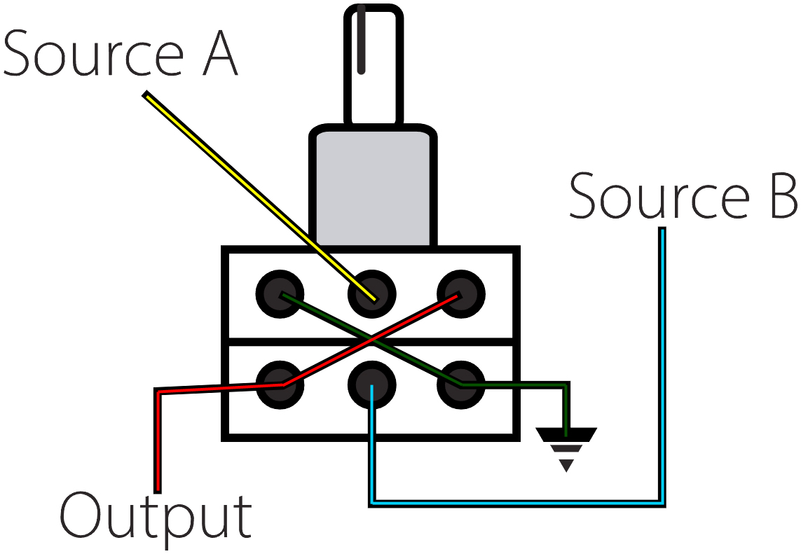
I tried anyway, and documented my experiments here so you don't waste your time. A blend control potentiometer is unlike a volume or tone knob. Those other knobs have one variable resistor, generally accepting signal from the center post and directing it to one post or the other based on the position of the control stalk. They are not all like this so take resistance measurements so you know what you have before you warm up your solder iron. For blending, you cannot simply direct 2 separate inputs into the outer posts to vary what comes out the middle (think like a hot-cold water faucet). It just doesn't work that way. A blend control knob is effectively 2 stacked volume or control knobs managed by a single central stalk. The idea is that when turned one way, the resistance on the upper variable goes one direction while the lower variable goes the opposite direction, depending on which posts you are comparing. In this way, you can control 2 levels to go in opposite or similar directions at the same time.
The blend pots are not always linear and do not all behave like this, though. The NM pot that I started with, for example, has a curve such that at the exact center both sources are at 100%. As the knob moves away from center, one of the stacks drops in volume (raises in resistance) while the other remains constant. In an "AC" knob, the curves are more parabolic, crossing at the middle. So, only at the extreme end is a signal at it's highest or lowest.
To help illustrate the wiring, I nabbed the image up above on the right, here, from a guitar forum post which was describing how to wire up a blend knob between 2 pickups. Similar to the volume knob, the decisions around the resistance value for the blend were not easy. On that forum, it was posed that a lower resistance range would create a smoother transition, so using a NM100k pot would be better than a NM250k pot. It was also made clear that the values of the blend had little to no bearing on the resistance value of an independent volume knob and vice-versa (volume no impact on blend value). Last, I have read varying accounts about grounding or not grounding the blend (black wire path in the drawing). I started with ungrounded cuz easier. It seemed to me that the lower the resistance value, the better the transition, so I got the lowest blend pot I could find: NM25k. I figured if it was too low and it effectively worked like a 3 position switch: all-On | 50-50 | all-Off it would still be better than not having it at all, and then I would explore other, higher resistance settings to find a true blend. Of course, this was all guitarists talking and when I went to some bass forums, it seemed that the lower resistance values would trim some of the bottom end tone. Regardless, I saw that after I'd gotten the NM25k.

So, I ordered an AC blend pot and dug into my electrical stuff for the not-gate diode that I used in Hapy's ignition before I re-wired him. I added it to the black-with-white-stripe wire on the left side of the image above, with the side with a stripe (cathode) pointing towards the blend knob. A not-gate diode is basically the same as a back-flow in your plumbing: it prevents the signal from going the wrong way. Signal can go from the anode to the cathode, but not the other way. I did not give 2 thinks about the size of the diode relative to my project, and the results were enlightening but not right. For Hapy's ignition, the amount of resistance was relatively meaningless since a ton of 12V signal was present. For this, where we are working with miliVolts, this diode introduces considerable resistance to the overall dry signal heading for the blend knob. So much resistance, in fact, that it virtually kills the dry signal, but the feedback stopped. I tried the cathode reversed but that didn't work either. Besides, I had it oriented correctly, it's just the wrong value.
In the end, I removed the diode and returned the unit to the way it was (volume control only). I intend to return when I can find an elegant solution, be it the correct diode or another entire circuit board to add in (maybe something like this). I'm hoping the former, but will do the later if I find I am enjoying the Q-Tron and want to adjust it that little bit more. I took the Q-Tron to a jam on Saturday with a few other pedals I don't get to play with very often, and found that adding a phaser after the Q-Tron took some of the bite out of the t-wah without losing the fun. It felt like some of the lower end came back thru the phaser too, so maybe there's hope for this pedal without a blend control. Time will tell.
Thanks, as always, for following along. I will return to my more typical car/bus/house stuff next time-


